CAME FROG Installation Manual
Swing-gate operator
Hide thumbs
Also See for FROG:
- Installation manual (65 pages) ,
- Installation manual (12 pages) ,
- Installation manual (16 pages)

Related Manuals for CAME FROG


Summary of Contents for CAME FROG
- Page 1 Automazioni per cancelli a battente FA01570M04 FROG FROG-A FROG-AV FROG-AE Italiano EN English MANUALE DI INSTALLAZIONE Français RU Русский...
-
Page 3: Avvertenze Generali Per L'installatore
Direttiva Macchine 2006/42/CE ed agli standard tecnici armonizzati di riferimento sono identificati nel catalogo generale dei prodotti CAME oppure nel sito internet www.came.com. • Durante tutte le fasi dell’installazione assicurarsi di operare fuori tensione. • Verificare che il range di temperature indicato sia adatto al luogo di installazione. - Page 4 • Se non già presente, applicare un’etichetta permanente che descriva come usare il meccanismo di sblocco manuale vicino al relativo elemento di azionamento. • Assicurarsi che l’automazione sia stata regolata adeguatamente e che i dispositivi di sicurezza e protezione, così come lo sblocco manuale, funzionino correttamente. • Prima della consegna all’utente, verificare la conformità...
-
Page 5: Descrizione Delle Parti
Questo simbolo indica cosa comunicare all’utente. Le misure, se non diversamente indicato, sono in millimetri. Descrizione FROG-A Motoriduttore interrato 230 V irreversibile con fermo anta in chiusura regolabile per cancelli a battente con ante fino a 3,5 m e 400 kg di peso. FROG-AV Motoriduttore interrato 230 V irreversibile, versione veloce, con fermo anta in chiusura regolabile per cancelli a battente con ante fino a 1,3 m e 300 kg di peso. -
Page 6: Limiti Di Impiego
Per i collegamenti di prodotti non contemplati in questo manuale fa fede la documentazione allegata ai prodotti stessi. Per il collegamento dell'Encoder, utilizzare un cavo tipo FRORPU 3 x 0,5mm2 o un cavo fornito da CAME su richiesta (codice articolo 801XA-0020). -
Page 7: Installazione
INSTALLAZIONE Le seguenti illustrazioni sono solo esempi in quanto lo spazio per il fissaggio dell’automazione e degli accessori varia a seconda della zona di installazione. Spetta all’installatore scegliere la soluzione più adatta. I disegni si riferiscono al motoriduttore installato a destra. Operazioni preliminari Le operazioni preliminari all’installazione riguardano la posa della cassa di fondazione e il fissaggio dei dispositivi di sblocco. - Page 8 Lubrificare la leva di trasmissione. Inserire la leva di trasmissione come indicato nei disegni. Determinazione dei punti di finecorsa con finecorsa meccanici Aprire manualmente l'anta fino al punto desiderato. L'apertura massima dell'anta è pari a 110°. Svitare la vite di regolazione del punto di finecorsa di apertura fino al contatto con la cassa di fondazione. Stringere il dado per bloccare la posizione della vite.
-
Page 9: Collegamenti Elettrici
COLLEGAMENTI ELETTRICI Prima di intervenire sul quadro di comando, togliere la tensione di linea e, se presenti, scollegare le batterie. Prevedere delle scatole di derivazione IP67 con morsettiere per i collegamenti. Motoriduttore con Encoder Cavo blu Cavo per l'alimentazione Cavo marrone Cavo dell'Encoder Cavo nero Cavo 801XA-0020... - Page 10 Motoriduttore senza Encoder Cavo blu Cavo marrone Cavo nero Cavo giallo-verde Verificare il corretto senso di rotazione del motoriduttore ed eventualmente invertire il collegamento dei cavi marrone e nero.
-
Page 11: Operazioni Finali
OPERAZIONI FINALI APERTURA VERSO L'ESTERNO Di seguito, è descritta l'unica operazione diversa rispetto all'installazione standard. Preparazione del motoriduttore Inserire la vite di regolazione del punto di finecorsa di chiusura nel braccio del motoriduttore. Motoriduttore installato a sinistra Motoriduttore installato a destra... - Page 12 CAME S.p.A. Via Martiri della Libertà, 15 31030 Dosson di Casier Treviso - Italy Tel. (+39) 0422 4940 Fax (+39) 0422 4941...
- Page 13 Swing-gate operator FA01570-EN FROG FROG-A FROG-AV FROG-AE INSTALLATION MANUAL EN English...
- Page 15 Machinery Directive (2006/42/EC) and with the reference harmonised technical standards are specified in the general CAME product catalogue or on the website www.came.com. • Make sure the mains power supply is disconnected during all installation procedures. • Check that the temperature ranges given are suitable for the installation site. • When excavating to lay the foundation box, ensure there is sufficient drainage to prevent water from stagnating inside it.
- Page 16 • If not already present, apply a permanent tag that describes how to use the manual release mechanism close to it. • Make sure that the operator has been properly adjusted and that the safety and protection devices and the manual release are working properly.
-
Page 17: Intended Use
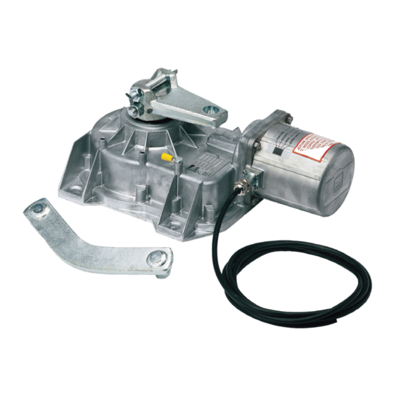
This symbol shows what to tell users. The measurements, unless otherwise stated, are in millimetres. Description FROG-A Underground irreversible 230 V gearmotor with adjustable leaf-stop during closing, for swing gates with leaves up to 3.5 m in length and 400 kg in weight. FROG-AV Quick-version underground irreversible 230 V gearmotor with adjustable leaf-stop during closing, for swing gates with leaves up to 1.3 m in length and 300 kg in weight. -
Page 18: Usage Limitations
For multiple, sequential loads along the same line, recalculate the values in the table according to the actual power draw and distances. For information on connecting products not covered in this manual, please see the documentation accompanying the products themselves. To connect the encoder, use a FRORPU 3 x 0.5 mm² cable or a cable supplied by CAME on request (item code 801XA-0020). -
Page 19: Installation
INSTALLATION The following illustrations are examples only. The space available for fitting the operator and accessories varies depending on the area where it is installed. It is up to the installer to find the most suitable solution. The drawings refer to the right-side gearmotor. Preliminary operations The preliminary operations for installation concern the foundation box installation and the release devices fastening. - Page 20 Lubricate the transmission lever. Fit the transmission lever as shown in the drawings. Determining the travel end points with mechanical limit switches Manually open the leaf to the desired point. The leaf maximum opening is 110°. Unscrew the opening limit-switch point adjustment screw until it touches the foundation box. Tighten the nut to lock the screw into position.
-
Page 21: Electrical Connections
ELECTRICAL CONNECTIONS Before working on the control panel, disconnect the mains power supply and remove the batteries, if any. Provide IP67 junction boxes with terminal blocks for connections. Gear motor with encoder Blue cable Power supply cable Brown cable Encoder cable Black cable 801XA-0020 cable Yellow/green cable... - Page 22 Gearmotor without Encoder Blue cable Brown cable Black cable Yellow/green cable Check the correct direction of rotation of the gearmotor and, if necessary, invert the connection of the brown and black cables.
-
Page 23: Final Operations
FINAL OPERATIONS OUTWARDS OPENING The only operation that is different from the standard installation is described below. Setting up the gearmotor Insert the closing limit-switch point adjustment screw into the gearmotor arm. Gearmotor installed on the left Gearmotor installed on the right... - Page 24 CAME S.p.A. Via Martiri della Libertà, 15 31030 Dosson di Casier Treviso - Italy Tel. (+39) 0422 4940 Fax (+39) 0422 4941...
-
Page 25: Manuel D'installation
Automatismes pour portails battants FA01570-FR FROG FROG-A FROG-AV FROG-AE MANUEL D'INSTALLATION Français... - Page 27 2006/42/CE et les normes techniques harmonisées de référence sont identifiés dans le catalogue général des produits CAME ou sur le site www.came.com. • S’assurer, durant toutes les phases d’installation, que l’automatisme est bien hors tension. • S'assurer que la température du lieu d'installation correspond à celle indiquée sur l'automatisme. •...
- Page 28 • À défaut d’étiquette, en appliquer une permanente qui décrive comment utiliser le mécanisme de déblocage manuel et la positionner près de l’élément d’actionnement. • S'assurer que l’automatisme a bien été réglé comme il faut et que les dispositifs de sécurité et de protection, tout comme le déblocage manuel, fonctionnent correctement. • Avant la livraison à...
-
Page 29: Utilisation Prévue
Ce symbole indique ce qui doit être communiqué à l'utilisateur. Les dimensions sont exprimées en millimètres, sauf indication contraire. Description FROG-A Motoréducteur irréversible enterré 230 V avec butée réglable du vantail en fermeture pour portails battants jusqu'à 3,5 m et 400 kg par vantail. FROG-AV Motoréducteur irréversible enterré... -
Page 30: Limites D'utilisation
Pour les connexions de produits non indiqués dans ce manuel, considérer comme valable la documentation jointe à ces derniers. Pour connecter l’encodeur, utiliser un câble type FRORPU 3 x 0,5 mm² ou un câble fourni par la société CAME (code article 801XA-0020). -
Page 31: Opérations Préliminaires
INSTALLATION Les illustrations suivantes ne sont que des exemples étant donné que l'espace pour la fixation de l'automatisme et des accessoires varie en fonction de la zone d'installation. C'est donc l'installateur qui doit choisir la solution la plus indiquée. Les dessins se réfèrent au motoréducteur installé à droite. Opérations préliminaires Les opérations préalables à... - Page 32 Lubrifier le levier de transmission. Installer le levier de transmission comme indiqué sur les dessins. Définition des points de fin de course avec butées de fin de course mécaniques Ouvrir manuellement le vantail jusqu'à la position souhaitée. L'ouverture maximale du vantail est de 110°. Dévisser la vis de réglage du point de fin de course de fermeture jusqu'au contact avec le caisson de fondation.
-
Page 33: Branchements Électriques
BRANCHEMENTS ÉLECTRIQUES Avant d'intervenir sur l'armoire de commande, mettre hors tension et déconnecter les éventuelles batteries. Prévoir des boîtiers de dérivation IP67 avec borniers de connexion. Motoréducteur avec Encodeur Câble bleu Câble d'alimentation Câble marron Câble de l’encodeur Câble noir Câble 801XA-0020 Câble jaune-vert Câble vert... - Page 34 Motoréducteur sans encodeur Câble bleu Câble marron Câble noir Câble jaune-vert Contrôler le sens de rotation correct du motoréducteur et inverser le cas échéant le raccordement des câbles marron et noir.
-
Page 35: Opérations Finales
OPÉRATIONS FINALES OUVERTURE VERS L'EXTÉRIEUR La seule opération différente par rapport à l’installation standard est décrite ci-après. Préparation du motoréducteur Insérer la vis de réglage du point de fin de course de fermeture dans le bras du motoréducteur. Motoréducteur installé à gauche Motoréducteur installé... - Page 36 CAME S.p.A. Via Martiri della Libertà, 15 31030 Dosson di Casier Treviso - Italy Tél. (+39) 0422 49 40 Fax (+39) 0422 49 41...
-
Page 37: Руководство По Монтажу
Автоматика для распашных ворот FA01570-RU FROG FROG-A FROG-AV FROG-AE РУКОВОДСТВО ПО МОНТАЖУ Русский... - Page 39 оборудования 2006/42/CE и гармонизированным техническим стандартам, указаны в общем каталоге продукции CAME или на сайте www.came.com. • Убедитесь в отсутствии напряжения перед каждым этапом монтажных работ. • Убеди- тесь в том, что указанный диапазон температур соответствует температуре окружающей среды в месте установки. •...
- Page 40 • Все фиксированные устройства управления должны быть хорошо видны после установки и находиться в таком по- ложении, чтобы панель управления находилась в прямой видимости, однако в достаточном отдалении от движущихся компонентов. Если устройство управления работает в режиме «Присутствие оператора», оно должно быть установлено на высоте...
-
Page 41: Условные Обозначения
Этот символ обозначает раздел, предназначенный для ознакомления конечного пользователя. Все размеры приведены в мм, если не указано иное. Описание FROG-A Самоблокирующийся привод для подземной установки ~230 В с регулируемым упором при закрывании для распашных ворот со створками длиной до 3,5 м и массой до 400 кг. -
Page 42: Габаритные Размеры
с учетом реальных показателей потребления и фактических расстояний. При подключении устройств, не рассматриваемых в этой инструкции, следует руководствоваться технической документацией на соответствующее изделие. Для подключения энкодера используйте кабель типа FRORPU 3 x 0,5 мм2 или кабель, предоставляемый компанией CAME (артикул изделия 801XA- 0020). -
Page 43: Предварительные Работы
МОНТАЖ Приведенные ниже рисунки носят иллюстративный характер, поскольку пространство для крепления автоматики и дополнительных принадлежностей может изменяться от случая к случаю. Выбор наиболее подходящего решения должен осуществляться монтажником во время установки. На рисунках показан монтаж привода справа. Предварительные работы К подготовительным работам перед монтажом относятся установка монтажного основания и закрепление устройств разблокировки. См. руководства по... - Page 44 Смажьте рычаг передачи. Вставьте рычаг передачи, как показано на рисунке. Определение крайних положений с механическими концевыми выключателями Откройте створку вручную до желаемого положения. Максимальный угол открывания створки составляет 110°. Открутите винт регулировки конечной точки открывания до соприкосновения с фундаментной коробкой. Затяните...
-
Page 45: Электрические Подключения
ЭЛЕКТРИЧЕСКИЕ ПОДКЛЮЧЕНИЯ Перед началом работ по эксплуатации, ремонту, настройке и регулировке блока управления отключите сетевое электропитание и/или отсоедините аккумуляторы. Подготовьте распределительные коробки IP67 с контактными панелями для подключений. Мотор-редуктор с энкодером Синий провод Кабель электропитания Коричневый провод Кабель энкодера Черный кабель Кабель... - Page 46 Привод без энкодера Синий провод Коричневый провод Черный кабель Желто-зеленый кабель Проверьте, что привод вращается в правильном направлении, и при необходимости поменяйте местами коричневый и черный провода.
-
Page 47: Заключительные Работы
ЗАКЛЮЧИТЕЛЬНЫЕ РАБОТЫ ОТКРЫВАНИЕ НАРУЖУ Далее описываются только работы, отличающиеся от стандартного монтажа. Подготовка привода Вставьте винт регулировки конечной точки закрывания в рычаг привода. Привод, установленный слева Привод, установленный справа... - Page 48 CAME S.p.A. Via Martiri della Libertà, 15 31030 Доссон-ди-Казьер Treviso - Italy (Италия) Тел.: (+39) 0422 4940 Факс: (+39) 0422 4941...
Need help?
Do you have a question about the FROG and is the answer not in the manual?
Questions and answers