
Related Manuals for Cumberland PNEG-942


Summary of Contents for Cumberland PNEG-942
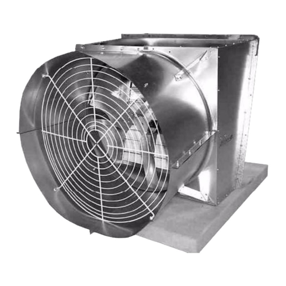
- Page 1 Belt Drive Galvanized Fans Installation and Operation Manual PNEG-942 Version: 7.0 Date: 06-28-22 PNEG-942...
- Page 2 All information, illustrations, photos and specifications in this manual are based on the latest information available at the time of publication. The right is reserved to make changes at any time without notice. PNEG-942 Belt Drive Galvanized Fans...
-
Page 3: Table Of Contents
Plastic Shutter Installation ........................37 Chapter 5 Troubleshooting ..........................38 Chapter 6 Replacement Parts List ........................39 36" Belt Drive Galvanized Fan Replacement Parts List ...............39 50" Belt Drive Galvanized Fan Replacement Parts List ...............39 Chapter 7 Warranty ..............................41 PNEG-942 Belt Drive Galvanized Fans... -
Page 4: Chapter 1 Safety
Personnel operating or working around equipment must read this manual. This manual must be delivered with equipment to its owner. Failure to read this manual and its safety instructions is a misuse of the equipment. ST-0001-4 PNEG-942 Belt Drive Galvanized Fans... -
Page 5: Cautionary Symbols Definitions
This symbol is used to address practices not related to NOTICE personal injury. This symbol indicates a general hazard. This symbol indicates a prohibited activity. This symbol indicates a mandatory action. ST-0005-2 PNEG-942 Belt Drive Galvanized Fans... -
Page 6: Safety Cautions
Learn how to operate the machine and how to use controls properly. Do not let anyone operate without instruction. • If you do not understand any part of this manual or need assistance, contact your dealer. ST-0002-1 PNEG-942 Belt Drive Galvanized Fans... - Page 7 The fan described in this manual is designed solely for the purpose of ventilating agricultural buildings. Use of the fan in any other way is a misuse of the equipment and may endanger health and safety. ST-0023-1 PNEG-942 Belt Drive Galvanized Fans...
- Page 8 ST-0018-2 Sharp Edge Hazard • This product has sharp edges, which can cause serious injury. • To avoid injury, handle sharp edges with caution and always use proper protective clothing and equipment. ST-0036-2 PNEG-942 Belt Drive Galvanized Fans...
-
Page 9: General Safety Statement
General Safety Statement Thank you for choosing a Cumberland Galvanized Fan. It is designed to give excellent performance and service for many years. Cumberland’s principle concern is your safety and the safety of others associated with poultry equipment. - Page 10 Correct Use of Your Galvanized Fans Only genuine Cumberland parts are to be used in the installation, maintenance and use of the Galvanized Fans. Use of other non-genuine parts is a misuse of the system and may lead to dangerous situations imperilling the safety and health of you and others.
- Page 11 The following pages show you exactly where the safety signs, warnings and other decals should be placed on the Galvanized Fans. If a decal is missing, damaged or unreadable, please contact your dealer or Cumberland, a member of GSI Group, for a free replacement. Installation Notes To ensure the safety during installation, make all electrical connections as the final step of installation.
- Page 12 (PLT) residue on any galvanized surfaces, as it will lead to premature rusting. To clean galvanized surfaces, use a water based emulsifier, alkaline based cleaners with a pH of 12 or lower or organic solvents. Then rinse the area with fresh water and wipe clean with a soft cloth. PNEG-942 Belt Drive Galvanized Fans...
-
Page 13: Safety Sign-Off Sheet
All unqualified persons are to stay out of the work area at all times. It is strongly recommended that another qualified person who knows the shut down procedure be in the area in the event of an emergency. Date Employee Name Supervisor Name ST-0007 PNEG-942 Belt Drive Galvanized Fans... -
Page 14: Chapter 2 Safety Decals
This manual describes the installation and operation for all standard production Galvanized Fans. Safety decals should be read and understood by all people in the Galvanized Fan area. If a decal has been damaged or is missing, contact Cumberland for a free replacement: Cumberland 1004 E. -
Page 15: Safety Decal Locations
WARNING HIGH VOLTAGE FLYING OBJECTS Will cause serious HAZARD injury or death. Lockout power Danger of eye injury. before servicing. Wear eye protection. The GSI Group 217-226-4421 DC-1540 Figure 2A PNEG-942 Belt Drive Galvanized Fans... -
Page 16: Chapter 3 Galvanized Fan Specifications
All of the above slant fans have a flat “step” at the flange and then begin to drop at 15°, except for the 36" cone fan, which begins the 15° drop right at the flange. It’s horizontal mounting materials should also be tilted to 15°. Figure 3A PNEG-942 Belt Drive Galvanized Fans... -
Page 17: Chapter 4 Belt Drive Galvanized Fan Assembly Instructions
Use 5/16"-18 x 1/2" hex washer head bolts and 5/16"-18 flange whiz nuts for Step 1 Step 2 on Page 18. Figure 4A NOTE: Three (3) holes in venturi must be in this position. Figure 4B Venturi and Bearing Support Plate PNEG-942 Belt Drive Galvanized Fans... - Page 18 4. Belt Drive Galvanized Fan Assembly Instructions Step 2 for All Belt Drive Fans Bearing support plate strut Figure 4C PNEG-942 Belt Drive Galvanized Fans...
-
Page 19: Fan Housing Assembly Instructions
Use #10-32 x 1/2" slotted hex head type F screws Box fan housing panel Figure 4D Use 5/16"-18 slotted truss head bolts and nuts for connection of bearing support plate to housing panels. Figure 4E PNEG-942 Belt Drive Galvanized Fans... - Page 20 Step 3A for 36" and 50" Box Fans (Continued) Direct drive shown for illustration purposes only. When assembling 50" box fan, note position of these four (4) holes to the rear of the fan. Figure 4F PNEG-942 Belt Drive Galvanized Fans...
- Page 21 4. Belt Drive Galvanized Fan Assembly Instructions Step 3B for 36" and 50" Slantwall Fans Use #10-32 x 1/2" slotted Bottom housing panel hex head type F screws Figure 4G Direct drive shown for illustration purposes only. Figure 4H PNEG-942 Belt Drive Galvanized Fans...
- Page 22 4. Belt Drive Galvanized Fan Assembly Instructions Step 3B for 36" and 50" Slantwall Fans (Continued) Direct drive shown for illustration purposes only. Left and right hand housing side panels Top housing panel Figure 4I PNEG-942 Belt Drive Galvanized Fans...
- Page 23 4. Belt Drive Galvanized Fan Assembly Instructions Step 3C for 50" Slantwall Cone Fans Use #10-32 x 1/2" slotted Top panel Bottom panel hex head type F screws Left and right hand side panels Figure 4J PNEG-942 Belt Drive Galvanized Fans...
- Page 24 4. Belt Drive Galvanized Fan Assembly Instructions Step 3C for 50" Slantwall Cone Fans (Continued) Figure 4K PNEG-942 Belt Drive Galvanized Fans...
- Page 25 Step 3D for 36" Slantwall Cone Fans Use #10-32 x 1/2" slotted Bottom panel hex head type F screws Figure 4L Direct drive shown for illustration purposes only. Left and right hand side panels Figure 4M PNEG-942 Belt Drive Galvanized Fans...
- Page 26 4. Belt Drive Galvanized Fan Assembly Instructions Step 3D for 36" Slantwall Cone Fans (Continued) Top panel Figure 4N Direct drive shown for illustration purposes only. Figure 4O PNEG-942 Belt Drive Galvanized Fans...
-
Page 27: Bearing/Drive Shaft Assembly Instructions (All Fans)
Use 3/8"-16 x 1-1/2" hex flange head bolts, 3/8" washers and 3/8" nylock nuts. Do not tighten at this time. Make sure there are two (2) washers between the head of bolt and the bearing and one washer between the bearing mount plate and the nylock nut. Figure 4Q PNEG-942 Belt Drive Galvanized Fans... - Page 28 Slide shaft through bearings, propeller will be placed on turned down end of shaft (50" no turn down). Eccentric lock collars are placed between the bearings with the lock mechanism pointing toward the bearing. (See Figure 4S.) Figure 4S PNEG-942 Belt Drive Galvanized Fans...
- Page 29 Slide the key in the keyway engaging the sheave to the drive shaft. Tighten the set screw on the shaft to 45 inch-pounds of torque. (See Figure 4U.) 3/4" 19 mm Figure 4U PNEG-942 Belt Drive Galvanized Fans...
- Page 30 Insert a punch into the drift holes on the outside of the collars and tap to set the collars. Again, ensure the collars are locked in the direction of shaft rotation (counterclockwise when facing the air inlet side). Tighten the set screws of the collars to 25 inch-pounds of torque. Figure 4W PNEG-942 Belt Drive Galvanized Fans...
-
Page 31: Motor Assembly And Mounting Instructions
Make sure the belt does not come out of the sheave as you are rotating the sheave. (See Figure 4Y.) Figure 4Y Ref # Description Ref # Description Bearing Support Plate Bolt and Washer PNEG-942 Belt Drive Galvanized Fans... - Page 32 Adjust the tensioner arm to the proper tension. The setting notch (C) should be aligned between the first set of adjustment notches (D). (See Figure 4Z.) Figure 4Z Ref # Description Setting Notch Adjustment Notch Figure 4AA Finished Belt Assembly PNEG-942 Belt Drive Galvanized Fans...
-
Page 33: Propeller Installation
Figure 4AB Wire Mesh Guard Installation Step 10 for All 36" and 50" Box (both sides) and Slantwall (discharge side) Belt Drive Fans Use #10-32 x 3/4" slotted hex head type F screws Figure 4AC PNEG-942 Belt Drive Galvanized Fans... - Page 34 NOTE: Trim the mesh on the side the motor protrudes through for box fans. Secure wire mesh guard and corner supports on both sides of fan with #10-32 x 3/4" hex washer head type “F” screws and 1-1/2" outer diameter washers as shown. Figure 4AF PNEG-942 Belt Drive Galvanized Fans...
-
Page 35: Cone And Guard Mounting Instructions
4. Belt Drive Galvanized Fan Assembly Instructions Cone and Guard Mounting Instructions Step 11 for All 36" and 50" Cone Fans Figure 4AG Direct drive shown for illustration purposes only. Figure 4AH PNEG-942 Belt Drive Galvanized Fans... - Page 36 4. Belt Drive Galvanized Fan Assembly Instructions Step 11 for All 36" and 50" Cone Fans (Continued) Direct drive shown for illustration purpose only. Assembly complete for 36" and 50" cone fans Figure 4AI PNEG-942 Belt Drive Galvanized Fans...
-
Page 37: Plastic Shutter Installation
#10 x 1/2" sheet metal screws, which are standard hardware and available locally. Figure 4AJ Ref # Part # Description Ref # Description Screw Shutter S-7279 3/16" Flat Washer Fan Housing 91-0042 Turn Button PNEG-942 Belt Drive Galvanized Fans... -
Page 38: Chapter 5 Troubleshooting
Fan blade has excessive build up of dirt. Clean unit. Power supply voltage is too low. Check line voltage at motor, verify wiring is of sufficient gauge for load and length of conductor. Check with local utility supplier for possible line problems. PNEG-942 Belt Drive Galvanized Fans... -
Page 39: Chapter 6 Replacement Parts List
16-0057 Belt Drive Drive Shaft 12-0493 Belt Drive Pulley (Propeller) 16-0016 Belt Drive Pulley (Motor) 91-0057 Belt Drive Tension Arm 10-0040 Shutter Mount Hardware Parts shown for 1 Phase, 60 Hz application. Call for others. PNEG-942 Belt Drive Galvanized Fans... - Page 40 NOTES PNEG-942 Belt Drive Galvanized Fans...
-
Page 41: Chapter 7 Warranty
GSI warrants, subject to all other conditions described in this Warranty, Service Parts which it manufactures for a period of 12 months from the date of purchase, unless specified in Enhancements above. Parts not manufactured by GSI will carry the Manufacturer’s Warranty. (Protein Limited Warranty_REV01_06 November 2018) PNEG-942 Belt Drive Galvanized Fans... - Page 42 This equipment shall be installed in accordance with the current installation codes and applicable regulations, which should be carefully followed in all cases. Authorities having jurisdiction should be consulted before installations are made. 1004 E. Illinois St. Assumption, IL 62510-0020 Phone: 1-217-226-4421 Fax: 1-217-226-4420 www.cumberlandpoultry.com...
Need help?
Do you have a question about the PNEG-942 and is the answer not in the manual?
Questions and answers