
Subscribe to Our Youtube Channel
Related Manuals for Cumberland AP Competitor Series


Summary of Contents for Cumberland AP Competitor Series
- Page 1 Competitor Series Fans Models: 12", 14", 18", 24", 36" AND 54" Installation and Operation Manual PNEG-1559 Version 10.0 Date: 05-22-24 PNEG-1559...
- Page 2 Congratulations! Thank you for purchasing a Competitor Series Fan, designed to give you years of high velocity air flow. With proper installation and maintenance, it will provide you many years of service. About this document Read all instructions and safety information before beginning installation. Retain these instructions for future reference.
-
Page 3: Table Of Contents
Contents Chapter 1 Safety Precautions ........................5 Safety Guidelines ........................5 Cautionary Symbol Definitions......................6 Safety Cautions...........................7 General Safety Information ......................10 Safety Decals ...........................12 Safety Sign-Off Sheet ........................15 Chapter 2 Product Information ........................17 Unpacking ..........................18 Fan Models..........................18 Fan Dimensions ........................19 Fan Spacing ..........................20 Hardware Identifications ......................22 Tools Required..........................22 Chapter 3... - Page 4 NOTES PNEG-1559 Competitor Series Fans...
-
Page 5: Chapter 1 Safety Precautions
Safety Precautions Topics Covered in this Chapter ▪ Safety Guidelines ▪ Cautionary Symbol Definitions ▪ Safety Cautions ▪ General Safety Information ▪ Safety Decals ▪ Safety Sign-Off Sheet Safety Guidelines Safety guidelines are general-to-specific safety rules that must be followed at all times. This manual is written to help you understand safe operating procedures and problems that can be encountered by the operator and other personnel when using this equipment. -
Page 6: Cautionary Symbol Definitions
Chapter 1: Safety Precautions Cautionary Symbol Definitions Cautionary symbols appear in this manual and on product decals. The symbols alert the user of potential safety hazards, prohibited activities and mandatory actions. To help you recognize this information, we use the symbols that are defined below. Table 1-1 Description of the different cautionary symbols Symbol Description... -
Page 7: Safety Cautions
Chapter 1: Safety Precautions Safety Cautions Use Personal Protective Equipment • Use appropriate personal protective equipment: Respiratory Foot Protection Protection Protection Hearing Head Fall Protection Protection Protection Hand Protection • Wear clothing appropriate to the job. • Remove all jewelry. •... - Page 8 Chapter 1: Safety Precautions Lifting Hazard • Single person lift can cause injury. • Use a mechanical lifting device to lift or move the equipment during installation. ST-0021–2 Explosion Hazard • The fan is not designed for use in atmospheres where the risk of explosion is present.
- Page 9 Chapter 1: Safety Precautions Install and Operate Fan Properly • Electrical controls and wiring must be installed by a qualified electrician and must meet the standards set by the National Electric Code, Canadian Electrical Code, and all local and state codes. The fan must be installed and maintained by a qualified person familiar with the use and function of ventilation fans.
-
Page 10: General Safety Information
Only genuine AP/Cumberland parts are to be used in the installation and use of the fan. Use of other non-genuine parts is a misuse of the system and may lead to dangerous situations jeopardizing the safety and health of you and others. -
Page 11: Maintenance Safety
Provisions for an adequate and safe power supply to the fan unit are essential to your safety. AP/Cumberland recommends a competent and qualified electrician undertake all electrical wiring. All wiring is to be installed in accordance with National, State and Local Electrical Codes. Fans used to ventilate livestock buildings and other rooms where continuous air movement is essential, should be connected to individual electrical circuits with a minimum of two circuits per room. -
Page 12: Safety Decals
Chapter 1: Safety Precautions Safety Decals The safety decals on your equipment are safety indicators which must be carefully read and understood by all personnel involved in the installation, operation, service and maintenance of the equipment. To replace a damaged of missing decal, contact us to receive a free replacement. GSI Decals 1004 E. - Page 13 Chapter 1: Safety Precautions Figure 1-2 Decal locations (cont'd.) PNEG-1559 Competitor Series Fans...
- Page 14 Chapter 1: Safety Precautions Table 1-2 Decal locations Ref# Fan Size Decal # Decals Locations Located at the middle on the left outside and right inside of the 54" and 54" CE DC-995 housing. Located at the middle on the left 12", 14", 18", 24", outside and right inside of the DC-1540...
-
Page 15: Safety Sign-Off Sheet
Chapter 1: Safety Precautions Safety Sign-Off Sheet Below is a sign-off sheet that can be used to verify that all personnel have read and understood the safety instructions. This sign-off sheet is provided for your convenience and personal record keeping. Employee Name Supervisor Name Date... - Page 16 NOTES PNEG-1559 Competitor Series Fans...
-
Page 17: Chapter 2 Product Information
Product Information Topics Covered in this Chapter ▪ Unpacking ▪ Fan Models ▪ Fan Dimensions ▪ Fan Spacing ▪ Hardware Identifications ▪ Tools Required PNEG-1559 Competitor Series Fans... -
Page 18: Unpacking
Chapter 2: Product Information Unpacking When receiving the unit, inspect carefully for any damage that may have occurred during transit. Shipping damage claim must be filed with carrier. Fan Models Table 2-1 Direct drive fans Description Part # Color Size Cone 12"... -
Page 19: Fan Dimensions
Chapter 2: Product Information Fan Dimensions Figure 2-1 Fan dimensions Table 2-3 Fan dimensions Rough Opening Cone Width Height Length Less Length with Cone (W x H) Diameter (A) Cone (D) Cone (E) Length (F) Models CS-12-DD 17.0ʺ x 17.0ʺ 20.14ʺ... -
Page 20: Fan Spacing
Chapter 2: Product Information Fan Spacing Figure 2-2 Center to center fan spacing (12", 14" and 18" Competitor Series Fans) PNEG-1559 Competitor Series Fans... - Page 21 Chapter 2: Product Information Figure 2-3 Center to center fan spacing (24", 36" and 54" Competitor Series Fans) PNEG-1559 Competitor Series Fans...
-
Page 22: Hardware Identifications
Chapter 2: Product Information Hardware Identifications Figure 2-4 Hardware size reference chart Table 2-4 Hardware quantity based on fan diameter Quantity Part Description 12"-18" 24" 36" 50" 54" Number F&P Bolt, Flange 5/16"-18 x 1" SS (Full Thread) S-7447 Screw, MS 5/16"-18 x 1-1/2", THP, SS S-10715 Washer, Fender 5/16"... -
Page 23: Chapter 3 Installation
Installation Topics Covered in this Chapter ▪ Framing ▪ Installing the Fan Housing ▪ Assembling and Installing the Cone ▪ Installing the Shutter ▪ Electrical Wiring PNEG-1559 Competitor Series Fans... -
Page 24: Framing
Chapter 3: Installation Framing Before You Begin Make sure that you have enough rough opening and there is enough space so that the fan flanges do not overlap. 1. Fans should be installed in an exterior wall located where there will be no obstructions to the flow of air into or out of the fan. -
Page 25: Installing The Fan Housing
Chapter 3: Installation Installing the Fan Housing Lifting Hazard. Single person lift can cause injury. Use multiple people or a mechanical lifting device to lift or move heavy equipment. WARNING 1. Drill 3/16" pilot holes (17) into the flange of the fan housing (25), making sure to space them evenly. For 24"... - Page 26 Chapter 3: Installation Installing the Grill Guard for Fans without Cones For 12"-36" fans without cone, the grill guard is already pre-assembled to the fan housing. For 54" fan without cone, the grill guard needs to be assembled. 1. Position the grill guard (11) in front of the fan housing (10) and make sure the eyelets (19) on the grill guard (11) align with the holes in the fan housing (10) at all positions.
-
Page 27: Assembling And Installing The Cone
Chapter 3: Installation Assembling and Installing the Cone Installing the Plastic Cone (14"-36" Fans) The 14"-24" plastic cones are one-piece cones and 36" plastic cone is a two piece cone. Holes are pre-drilled into the cones for all connections and will need to be assembled before installing them onto the fan housing. - Page 28 Chapter 3: Installation 4. Lift the cone panel (13) onto the fan orifice (21) and align the holes in the cone with the holes in the fan (12) orifice. 5. Fasten the cone panel (13) to the fan orifice (21) using 5/16" x 1" flange bolts (1), 5/16" fender washers (4) and 5/16"...
- Page 29 Chapter 3: Installation Installing the Grill Guard for Plastic Cones (14"-36" Fans) All fans must have a grill guard installed before operating. For fans without cones, the grill guard will fasten directly to the fan orifice. For fans with cones, the grill guard will fasten to the cone. 1.
- Page 30 Chapter 3: Installation Installing the Plastic Cone (54" Fans) 54" plastic cones have four pieces. These cone pieces will need to be assembled together before installing them onto the fan housing. 1. Place the cone panels (14) on a flat surface and overlap them with the raised edge to the outside. 2.
- Page 31 Chapter 3: Installation 4. Fasten the cone assembly (20) to the fan orifice (21) using 5/16" x 1-1/2" MS screws (2), 5/16" fender washers (4) and 5/16" flange nuts (6). NOTE: • Make sure the MS screw (2) heads are on the inside of the fan orifice (21). •...
- Page 32 Chapter 3: Installation Installing the Grill Guard for Plastic Cone (54" Fans) All fans must have a grill guard installed before operating. For fans without cones, the grill guard will fasten directly to the fan orifice. For fans with cones, the grill guard will fasten to the cone. 1.
- Page 33 Chapter 3: Installation Installing the Fiberglass Cone (54" Fans) 54" fiberglass cones have four pieces. These cones will need to be assembled together before installing them onto the fan housing. 1. Position the cone panels (9) so that end with slots in one panel (9) overlaps the end with holes in other panel (9).
- Page 34 Chapter 3: Installation 3. Lift the cone assembly (20) onto the fan orifice (21) and align the holes in the cone assembly (20) with the holes in the fan orifice (21). 4. Fasten the cone assembly (20) to the fan orifice (21) using 5/16" x 1" flange bolts (1), 5/16" fender washers (4) and 5/16"...
- Page 35 Chapter 3: Installation Installing the Grill Guard for Fiberglass Cone (54" Fans) All fans must have a grill guard installed before operating. For fans without cones, the grill guard will fasten directly to the fan orifice. For fans with cones, the grill guard will fasten to the cone. 1.
-
Page 36: Installing The Shutter
Chapter 3: Installation Installing the Shutter Fan shutters are installed using turn buttons that make it easy to remove when servicing the fan. 12"-24" fans have eight turn buttons and 36"-54" fans have twelve turn buttons. 1. Insert the shutter assembly (22) into the fan housing (25). 2. -
Page 37: Electrical Wiring
Chapter 3: Installation Electrical Wiring All wiring should be installed in accordance with National, State and Local electrical codes. Fans used to ventilate livestock buildings or other rooms where continuous air movement is essential should be connected to individual electrical circuits, with a minimum of two circuits per room. We strongly recommend the installation of supplementary natural ventilation as well as a back-up thermostat and an alarm system on at least one cooling stage. -
Page 38: Three Phase
Chapter 3: Installation Figure 3-17 Single phase wiring diagram for belt drive fans Three Phase Figure 3-18 Three phase wiring diagram PNEG-1559 Competitor Series Fans... -
Page 39: Recommended Wire Routing
Chapter 3: Installation Figure 3-19 Three phase NEMA connections Recommended Wire Routing It is important to keep the power cable securely fastened and out of the way of the pulley and propeller. 1. As the power cable exits the motor, form a Drip Loop, and then run the power cable through electrical conduit. - Page 40 NOTES PNEG-1559 Competitor Series Fans...
-
Page 41: Chapter 4 Operation And Maintenance
Operation and Maintenance Topics Covered in this Chapter ▪ Initial Start-Up ▪ Maintenance Initial Start-Up 1. With electrical power OFF, verify that the fan propeller turns freely and that all fasteners are secure. 2. Turn ON electrical power and confirm that the fan operates smoothly, and the propeller is rotating the correct direction. - Page 42 Chapter 4: Operation and Maintenance Lubrication: • The motor and shaft bearings are lubricated at the factory. The motor bearings should never require lubrication over the life of the fan. • Pillow block bearings should be re-lubricated every thirty operating days and/or after each wash down cycle with three shots of grease or until fresh grease is seen purging past seal.
-
Page 43: Chapter 5 Troubleshooting
Troubleshooting Troubleshooting Guide Symptom Probable Cause(s) Corrective Action(s) Defective motor bearing. Replace. Parts are not securely Check all bolts, screws and fasteners anchored. De-energize fan. Turn propeller and check tip clearance. Do they appear to be approximately Excessive noise the same? Damaged fan blade NOTE: They can be a little different without any problems. - Page 44 NOTES PNEG-1559 Competitor Series Fans...
-
Page 45: Chapter 6 Winterizing
Winterizing If you do not operate your ventilation system at full capacity during colder months, you may want to “winterize” the fans that will not be used to reduce heat loss and condensation. To winterize: 1. Turn the fan control OFF. 2. - Page 46 NOTES PNEG-1559 Competitor Series Fans...
-
Page 47: Chapter 7 Parts List
Parts List Topics Covered in this Chapter ▪ Fan Parts ▪ 12" Competitor Series Fan Parts ▪ 14" Competitor Series Fan Parts ▪ 18" Competitor Series Fan Parts ▪ 24" Competitor Series Fan Parts ▪ 36" Competitor Series Fan Parts ▪... -
Page 48: Fan Parts
Chapter 7: Parts List Fan Parts Description Part # Color Size Cone 12" Competitor Fan, Direct Drive, No Cone, PVC Shutter CS-12-DD-NC 12" None 14" Competitor Fan, Direct Drive, No Cone, PVC Shutter CS-14-DD-NC None 14" Poly 14" Competitor Fan, Direct Drive, Poly Cone, PVC Shutter CS-14-DD-PC 18"... -
Page 49: 12" Competitor Series Fan Parts
Chapter 7: Parts List 12" Competitor Series Fan Parts Figure 7-1 12" Competitor series fan parts (No Cone) Table 7-1 12" Competitor series fan parts list (No Cone) Description Ref # Part # No Cone 12-0117 Housing, APP-12 Fiberglass PSG2-15 Shutter, Plastic 15.875"... -
Page 50: 14" Competitor Series Fan Parts
Chapter 7: Parts List 14" Competitor Series Fan Parts Figure 7-2 14" Competitor series fan parts (No Cone and Poly Cone) Table 7-2 14" Competitor series fan parts list (No Cone and Poly Cone) Description Ref # Part # Poly Cone No Cone 12-0086F Housing, APP-14 Fiberglass... -
Page 51: 18" Competitor Series Fan Parts
Chapter 7: Parts List 18" Competitor Series Fan Parts Figure 7-3 18" Competitor series fan parts (No Cone and Poly Cone) Table 7-3 18" Competitor series fan parts list (No Cone and Poly Cone) Description Ref # Part # Poly Cone No Cone Housing, APP-18 Fiberglass 12-0084F... -
Page 52: 24" Competitor Series Fan Parts
Chapter 7: Parts List 24" Competitor Series Fan Parts Figure 7-4 24" Competitor series fan parts (No Cone and Poly Cone) Table 7-4 24" Competitor series fan parts list (No Cone and Poly Cone) Description Ref # Part # Poly Cone No Cone Housing, APP-24 Fiberglass 12-0083F... -
Page 53: 36" Competitor Series Fan Parts
Chapter 7: Parts List 36" Competitor Series Fan Parts Figure 7-5 36" Competitor series fan parts (No Cone and Poly Cone) Table 7-5 36" Competitor series fan parts list (No Cone and Poly Cone)) Description Ref # Part # No Cone Poly Cone Housing, APP-36 Fiberglass 12-0091 Motor, 1/2 HP, 900 RPM, 1 PH, 115V/230V... -
Page 54: 54" Competitor Series Fan Parts
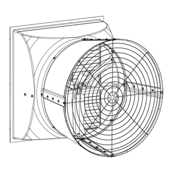
Chapter 7: Parts List 54" Competitor Series Fan Parts Figure 7-6 54" Competitor series fan parts (No Cone) PNEG-1559 Competitor Series Fans... - Page 55 Chapter 7: Parts List Table 7-6 54" Competitor series fan parts (No Cone) Description Ref # Part # CS541-NC CS543-NC 12-0258 Housing, 54" Fiberglass 11-0470-BLK Guard, Grill for CMDR-54 and CS54 without Cone - Black 3017-3101 Motor, 1.5 HP, 1 PH, 1725/1425 RPM, 208-230V, 50/60 Hz 15-0200 Motor, 1.75 HP, 3 PH 208-230/460V, 50/60 Hz, 4.9-5.0/3.0A 16-0016...
- Page 56 Chapter 7: Parts List Figure 7-7 54" Competitor Series Fan parts (Fiberglass Cone and Poly Cone) PNEG-1559 Competitor Series Fans...
- Page 57 Chapter 7: Parts List Table 7-7 54" Competitor Series Fan parts (Fiberglass Cone and Poly Cone) Description Ref # Part # Fiberglass Poly Cone Cone Table 7-8, page 58 Cone, 54" Fiberglass Panel Table 7-9, page 58 Cone, 54" HDPE Panel Table 7-8, page 58 Guard, Grill for CMDR-54 and CS54 without Cone - Black Table 7-9, page 58...
- Page 58 Chapter 7: Parts List Table 7-8 Cone, motor, grill guard and sheave part numbers (Fiberglass Cone) Fan models Ref # CS54C1-P CS54C1-E CS54C3-P CS54C3-E 12-0259 12-0259 12-0259 12-0259 11-0255-BLK 11-0255-BLK 11-0255-BLK 11-0255-BLK 3017-3101 3017-3101 15-0200 15-0200 16-0016 017-1391-6 16-0016 017-1391-6 Table 7-9 Cone, motor, grill guard and sheave part numbers (Poly Cone) Fan models Ref #...
-
Page 59: Limited Warranty - Protein Products
Performer Series Direct Drive Fan Motor 3 Years ® end user Flex-Flo/Pan Feeding System Motors ® and Cumberland ® 2 Years 3 to 5 years - end user pays 25% 5 to 7 years - end user pays 50% 24 Months from date... - Page 60 This equipment shall be installed in accordance with the current installation codes and applicable regulations which should be carefully followed in all cases. Authorities having jurisdiction should be consulted before installations are made. 1004 E. Illinois St. Assumption, IL 62510-0020 Phone: 1-217-226-4421 Fax: 1-217-226-4420 www.automatedproduction.com / www.cumberlandpoultry.com...
Need help?
Do you have a question about the AP Competitor Series and is the answer not in the manual?
Questions and answers