Agora Models FDNY FIRE TRUCK TOWER LADDER 9 Build Instructions
Hide thumbs
Also See for FDNY FIRE TRUCK TOWER LADDER 9:
- Build instructions (56 pages) ,
- Build instructions (32 pages)
Advertisement
Quick Links
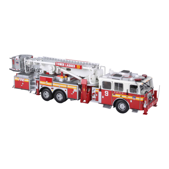
FIRE TRUCK
TOWER LADDER 9
Pack 09
B U I L D
I N S T R U C T I O N S
STAGE 58: ASSEMBLING THE TURNTABLE
STAGE 61: COMPONENTS FOR THE RIGHT-
STORAGE UNIT
HAND BOOM SECTION
STAGE 59: ASSEMBLING THE BOOM SUPPORT
STAGE 62: FIT TING THE BOOM SECTION TO
AND ATTACHING THE MAIN BODY TO
THE BOOM SUPPORT
THE CHASSIS
STAGE 60: COMPONENTS FOR THE LEFT-
HAND BOOM SECTION
Advertisement

Subscribe to Our Youtube Channel
Related Manuals for Agora Models FDNY FIRE TRUCK TOWER LADDER 9


Summary of Contents for Agora Models FDNY FIRE TRUCK TOWER LADDER 9
- Page 1 FIRE TRUCK TOWER LADDER 9 Pack 09 B U I L D I N S T R U C T I O N S STAGE 58: ASSEMBLING THE TURNTABLE STAGE 61: COMPONENTS FOR THE RIGHT- STORAGE UNIT HAND BOOM SECTION STAGE 59: ASSEMBLING THE BOOM SUPPORT STAGE 62: FIT TING THE BOOM SECTION TO AND ATTACHING THE MAIN BODY TO...
- Page 2 Advice from the experts Please keep ALL unused screws as they will be required in a later stage. Please make sure you don’t mix up the screws. They look quite similar, but the threads do vary slightly. Using the wrong screws may damage the parts. When securing parts together using multiple screws, fit each screw loosely to ensure all the parts are correctly aligned before gently tightening them firmly, but not overtight, in the order in which you placed them.
- Page 3 Stage 58: Assembling the Turntable Storage Unit In pack 9, the focus will be on the all-important boom. You’ll begin by assembling the storage unit located on the turntable. S T A G E 5 8 P A R T S L I S T Name Water pipe Small cabinet...
- Page 4 Stage 58: Assembling the Turntable Storage Unit A S S E M B L I N G T H E S T O R A G E U N I T Press the hinge securely onto the door. First, you’ll assemble the small cabinet that sits within the storage unit.
- Page 5 Stage 58: Assembling the Turntable Storage Unit Fit the second handle and door lock onto the opposite side of Apply a little glue to the recess on the storage unit as the storage unit. indicated in the picture above. Slide the small panel into place in the recess - note the This shows the small panel correctly in position.
- Page 6 Stage 58: Assembling the Turntable Storage Unit Align the small cabinet with the storage unit in the Push the small cabinet into position. orientation shown. Take the storage unit panel and note how the fixing points on Press firmly to fix into position, applying a little glue if the back correspond to the holes on the storage unit.
- Page 7 Stage 58: Assembling the Turntable Storage Unit S T A G E C O M P L E T E AGORAMODELS FDNY FIRE TRUCK...
- Page 8 Stage 59: Assembling the Boom Support and Attaching the Main Body to the Chassis Your Ladder 9 Fire Truck will start to take shape as you attach the boom support to the turntable, attach the turntable, and connect the main body to the chassis.
- Page 9 Stage 59: Assembling the Boom Support and Attaching the Main Body to the Chassis 2 x Type D A S S E M B L I N G T H E B O O M S U P P O R T A N D T U R N T A B L E Place the boom control tie onto the raised screw holes, and Take the boom support with the underside facing you, and push firmly over the pins.
- Page 10 Stage 59: Assembling the Boom Support and Attaching the Main Body to the Chassis Type K Hook 1 x hinge spring onto the straight end of the left boom Hook the free end of the spring onto the raised screw post hinge.
- Page 11 Stage 59: Assembling the Boom Support and Attaching the Main Body to the Chassis Type K Hook the remaining hinge spring onto the straight end of Once both hinges and springs are in place on the hinge the right boom hinge. Then hook the other end of the spring support, secure the hinge support from the outside of the onto the raised screw post and secure in place using another boom support using the support nut.
- Page 12 Stage 59: Assembling the Boom Support and Attaching the Main Body to the Chassis 2 x Type C Secure the boom support to the turntable using 2 x Type C Check that the boom control button operates the spring. screws. Type C Position the boom control-button cover over the button.
- Page 13 Stage 59: Assembling the Boom Support and Attaching the Main Body to the Chassis 2 x Type C Prepare to fix the storage cupboard assembled in stage 58 to Flip the turntable over and secure the cupboard from the the turntable. Locate the fixing points on the bottom of the underside using 2 x Type C screws.
- Page 14 Stage 59: Assembling the Boom Support and Attaching the Main Body to the Chassis Push the 2 x footrests into the small holes on the boom Push the handrail into position on the narrow edge of the support as shown. The flat side of each footrest faces up. boom support.
- Page 15 Stage 59: Assembling the Boom Support and Attaching the Main Body to the Chassis The turntable should sit comfortably in position. You’ll now need to work on the underside of the model. We recommend using two pieces of thick foam as supports at both ends.
- Page 16 Stage 59: Assembling the Boom Support and Attaching the Main Body to the Chassis Hook the steering bracket to the post on the underside of the cab as shown. Prepare to attach the main body to the chassis by aligning the two sections. You will also need the Type J screws.
- Page 17 Stage 59: Assembling the Boom Support and Attaching the Main Body to the Chassis Flatten all the cables on the main body, taping them down to keep them in place. This is necessary to ensure a good fit between the body and the chassis. Lower the chassis onto the main body, starting at the front end.
- Page 18 Stage 59: Assembling the Boom Support and Attaching the Main Body to the Chassis Here you can see the brackets under the front bumper that the chassis must hook around (inset), and also the chassis correctly fitted (arrows, main image). Once the front edge is hooked around the brackets shown in step 34, lower the chassis onto the body.
- Page 19 Stage 59: Assembling the Boom Support and Attaching the Main Body to the Chassis Prepare the handrail and handrail washers from Stage 47 Locate the 2 small holes on the turntable. Place a handrail washer in each hole. AGORAMODELS FDNY FIRE TRUCK...
- Page 20 Stage 59: Assembling the Boom Support and Attaching the Main Body to the Chassis Apply a little glue to the handrail posts before fixing it into the washers. S T A G E C O M P L E T E AGORAMODELS FDNY FIRE TRUCK...
- Page 21 Stage 60: Components for the Left-hand Bed Section In the next two stages, you’ll start to assemble the first boom section, known as the Bed Section. Stage 60 adds components to the left-hand side, stage 61 mirrors these steps for adding components to the right- hand side.
- Page 22 Stage 60: Components for the Left-hand Bed Section Take the ladder name plates supplied with stage 1 and stage 9. Note that the fixing brackets on either side are of different lengths. 4 x Type C Fix the name plate with the shorter brackets to the left-hand bed section using 4 x Type C screws.
- Page 23 Stage 60: Components for the Left-hand Bed Section Take the spotlight and spotlight lens. Apply a little PVA glue before attaching the lens to the spotlight. Apply a little glue and fix the Aerialscope 75 name plate in the recess on the front of the bed section. Push the spotlight into the hole at the end of the bed section in the orientation shown.
- Page 24 Stage 60: Components for the Left-hand Bed Section S T A G E C O M P L E T E AGORAMODELS FDNY FIRE TRUCK...
- Page 25 Stage 61: Components for the Right-hand Bed Section The same steps are repeated for adding components to the right- hand boom section. S T A G E 6 1 P A R T S L I S T Name Right-hand bed section Name plate Spotlight lens Spotlight...
- Page 26 Stage 61: Components for the Right-hand Bed Section 4 x Type C Fix the name plate with the longer brackets to the right-hand bed section using 4 x Type C screws. Apply a little glue and fix the Aerialscope 75 name plate in the recess on the front of the bed section.
- Page 27 Stage 61: Components for the Right-hand Bed Section Take the spotlight and spotlight lens. Apply a little PVA glue before attaching the lens to the spotlight. Push the spotlight into the hole at the end of the bed section in the orientation shown. The light should face the end of the section.
- Page 28 Stage 62: Fitting the Bed Section to the Boom Support In the next stage, the two halves of the bed section are fitted together. The cogs will be attached before fixing the bed section to the boom support. This pack is then completed with the start of the hose assembly.
- Page 29 Stage 62: Fitting the Bed Section to the Boom Support Type C A S S E M B L I N G T H E B E D S E C T I O N Flip the bed section over and fix the ladder bracket in place Take the ladder bracket and the right hand bed section.
- Page 30 Stage 62: Fitting the Bed Section to the Boom Support 2 x Type C 2 x Type C Fit the right boom cog to the right-hand side of the bed Repeat this step to fit the left boom cog to the left-hand side, section using 2 x Type C screws.
- Page 31 Stage 62: Fitting the Bed Section to the Boom Support Secure the hinge support by screwing on the remaining Movement of the boom is operated by the boom control support nut from stage 59. button. Check its operation now by pressing it firmly. As you press the button, gently lift the boom to disengage it from the cog before raising and lowering.
- Page 32 Stage 62: Fitting the Bed Section to the Boom Support The elevator pistons from stage 47 can now be fitted. Slide one of the pistons into the piston tube on the boom support. Type G Fit the free end of the piston into the piston bracket. Fix it in place with a Type G screw.
- Page 33 Stage 62: Fitting the Bed Section to the Boom Support Type H Type G Repeat steps 11–14 on the opposite side. First attach the right- Slide the remaining piston from stage 47 into the piston hand piston bracket using a Type H screw. tube.
- Page 34 Stage 62: Fitting the Bed Section to the Boom Support Pipe b Pipe c Push the water pipe into the fixing points in the orientation Push pipe c into the end of the water pipe; then add pipe b so shown.
Need help?
Do you have a question about the FDNY FIRE TRUCK TOWER LADDER 9 and is the answer not in the manual?
Questions and answers