Advertisement
Quick Links
L L
T T
ONDON TRANSPOR
ONDON TRANSPOR
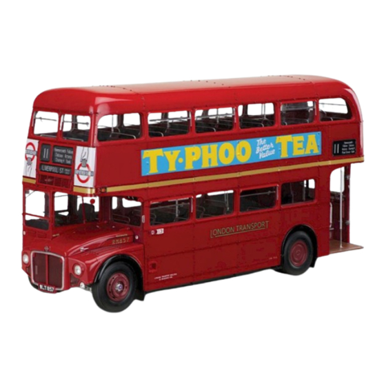
ROUTEMASTER BUS
RM 857
Pack 04
B U I L D
I N S T R U C T I O N S
STAGE 31: FITTING THE REAR WHEEL ARCHES
STAGE 36: THE FLOOR OF THE DRIVER'S
CAB AND THE HANDBRAKE
STAGE 32: FIT TING THE LEFT FRONT
WHEEL ARCH AND FOG LAMP
STAGE 37: BRAKE PEDAL AND ACCELERATOR
STAGE 33: FIT TING THE FRONT RIGHT
STAGE 38: FITTING THE DASHBOARD AND
WHEEL ARCH
ACCESSORIES IN THE CAB
STAGE 34: FUEL TANK, FUEL FILLER
STAGE 39: ASSEMBLING AND FIT TING
AND SAFETY BARS
THE DRIVER'S SEAT
STAGE 35: THE FLOOR OF THE DRIVER'S CAB AND
STAGE 40: FITTING ACCESSORIES IN THE
THE HANDBRAKE
DRIVER'S CAB
Advertisement

Related Manuals for Agora Models LONDON TRANSPORT ROUTEMASTER BUS


Summary of Contents for Agora Models LONDON TRANSPORT ROUTEMASTER BUS
- Page 1 ONDON TRANSPOR ONDON TRANSPOR ROUTEMASTER BUS RM 857 Pack 04 B U I L D I N S T R U C T I O N S STAGE 31: FITTING THE REAR WHEEL ARCHES STAGE 36: THE FLOOR OF THE DRIVER’S CAB AND THE HANDBRAKE STAGE 32: FIT TING THE LEFT FRONT WHEEL ARCH AND FOG LAMP...
- Page 2 RM 857 STAGE 31 FITTING THE REAR FITTING THE REAR WHEEL ARCHES WHEEL ARCHES In this stage, the rear mud flaps are attached to the rear wheel arches. The wheel arches are then attached to the sub-frame. KEY TO PARTS SUPPLIED Right mud flap Left rear wheel arch 2.3 x 5mm (x10)
- Page 3 RM 857 Take the left mud flap and the left rear wheel arch . Align the screw holes and sockets. Fix together with three screws. Take the right mud flap and the right rear wheel arch, . Align the screw eyes and sockets and fix in place with three screws.
- Page 4 RM 857 Take the sub-frame assembly and identify the fixing points for the left rear wheel arch on part . Fix the wheel arch in place with four screws. Identify the fixing points for the right rear wheel arch on the sub-frame .
- Page 5 RM 857 Finished views AGORAMODELS ROUTEMASTER BUS...
-
Page 6: Assembly Guide
RM 857 Assembly guide The rear wheel and wheel arch of Routemaster RM1 (left). The mud flap hangs behind the wheel, below the bodywork, to prevent excess mud On Routemaster from splashing up to the RM597 (below), suspension mechanism the exhaust is just behind the wheels. - Page 7 RM 857 STAGE 32 FITTING THE LEFT FRONT WHEEL FITTING THE LEFT FRONT WHEEL ARCH AND FOG LAMP ARCH AND FOG LAMP In this stage, we start the electrical wiring, to provide a connection for the fog lamp that is attached to the Left front wheel arch.
- Page 8 RM 857 Take the wheel arch and the mud flap . Check that Take the fog lamp . Identify the fixing you have part the right way round, to match the diagram. point on part . Fix the fog lamp in Identify the three fixing points along the lower edge of the wheel place with an screw...
- Page 9 RM 857 Note that the cable 32E has a connector at one end. This end goes towards the rear of the bus. Step 5 shows the correct position for this end of the cable on the frame. When fitting the cable, ensure there is enough free at the front for the LED bulb to reach the fog light (see...
- Page 10 RM 857 Turn the sub-frame assembly Turn the sub-frame assembly on its side, so that you can on its side, so that you can see the back of the fog lamp 32C. see the back of the fog lamp Take care to protect the engine, to Take care to protect the engine, prevent any damage.
- Page 11 RM 857 Finished view Assembly guide AGORAMODELS ROUTEMASTER BUS...
- Page 12 RM 857 STAGE 33 FITTING THE FRONT RIGHT FITTING THE FRONT RIGHT WHEEL ARCH WHEEL ARCH The right front mud flap is fitted to the corresponding wheel arch and then the assembly is attached to the frame. The front right wheel KEY TO PARTS arch of SUPPLIED...
- Page 13 RM 857 Make sure that you have the mud flap the right Take the right front wheel arch and the mud way round, positioning flap . Identify the three screw holes on part the cut-out corner at the top right, as and the corresponding sockets on part .
- Page 14 RM 857 The GM screws are shown here in silver, for clarity, but the screws supplied are black. This diagram shows the right front wheel arch fixed in place. The three screws are circled in red. Assembly guide AGORAMODELS ROUTEMASTER BUS...
- Page 15 RM 857 Finished views Two views of the subframe with all four wheel arches in place. AGORAMODELS ROUTEMASTER BUS...
- Page 16 RM 857 STAGE 34 FUEL TANK, FUEL FILLER AND FUEL TANK, FUEL FILLER AND SAFETY BARS SAFETY BARS The fuel tank is attached to the sub-frame, and the filler neck and cap are attached. The safety bars are fitted along the length of the frame. Be careful to identify all the parts before starting the build.
- Page 17 RM 857 Handle the frame with care when working on the underside. The red dotted lines (below) indicate where the pegs are fitted, and the blue arrows indicate where the screws are fitted. Identify the fixing points for the brackets on the underside of the crossbars of the frame .
- Page 18 RM 857 positions of the fixing points are indicated by red circles. They are not clearly visible in this diagram. Identify the fixing points for the brackets on the crossbars of the frame on the other side of the frame. Again, there is a screw hole and a socket at each point.
- Page 19 RM 857 Take the filler cap Take the fuel filler neck insert the screw eye between and identify its fixing point on the arms of the fuel filler base, as the frame . Fix the fuel filler cap indicated by the dotted line. Fix assembly in place with two screws in place with a...
- Page 20 RM 857 Assembly guide Finished views Nearside and offside views of the sub-frame, resting on the cradle supports, with the bars in place. AGORAMODELS ROUTEMASTER BUS...
- Page 21 RM 857 STAGE 35 THE FLOOR OF THE DRIVER’S CAB THE FLOOR OF THE DRIVER’S CAB AND THE HANDBRAKE AND THE HANDBRAKE The floor and nearside wall of the driver’s cab are fitted together and some of the controls are then fitted in place.
- Page 22 RM 857 Take the driver’s cab floor and the driver’s cab left wall With the parts oriented as shown in the diagram, align the two large screw holes on the lower edge of part with the holes in the lip of part as indicated by the dotted lines.
- Page 23 RM 857 Still working on the underside of the floor, take the support bracket and fit it over the part so that the holes in part align with the raised screw sockets in part , on either side of part .
- Page 24 RM 857 Take the engine stop control and fit the two pegs into the corresponding sockets on the driver’s cab left wall . This is a push-fit NOTE: connection. One of the pegs is larger, to ensure you get part right way round.
- Page 25 RM 857 Finished views Two views of the driver’s cab floor with the handbrake, dip switch and engine stop switch fixed in place. AGORAMODELS ROUTEMASTER BUS...
- Page 26 RM 857 STAGE 36 THE FLOOR OF THE DRIVER’S CAB THE FLOOR OF THE DRIVER’S CAB AND THE HANDBRAKE AND THE HANDBRAKE The floor and nearside wall of the driver’s cab are fixed together and some of the controls are then fitted in place. KEY TO PARTS SUPPLIED Push rod Steering wheel...
- Page 27 RM 857 Take the steering shaft and fit it into the gear box Fit the raised square section of the rocker lever section . Ensure the ridges on part fit into the into the opening in the gear box section neck of part , as indicated by the red dotted lines.
- Page 28 RM 857 Take the driver’s cab floor and wall assembly from the previous stage. Fit the end of part into the large hole in part Take the gear box assembly from step 3. Fit part into the steering column from beneath the floor. AGORAMODELS ROUTEMASTER BUS...
- Page 29 RM 857 Carefully turn the assembly over, keeping all the pieces in place. Fix the gear box assembly in place with two screws: they go through the screw holes in parts , into the raised screw sockets in part Take the gear lever assembly from step Fit the steering wheel 36A over the end of the steering 4 and fit part over the top of the...
- Page 30 RM 857 Finished views The driver’s cab floor with the steering column in place. The horn and gear lever are attached to the column. Store carefully, to avoid damaging the push rod beneath the floor. In this view of a Routemaster cab, the horn column is on the right below the steering wheel and the gear lever is...
- Page 31 RM 857 STAGE 37 BRAKE PEDAL AND BRAKE PEDAL AND ACCELERATOR ACCELERATOR Several small parts are supplied in this stage, which enable you to fit the brake pedal and accelerator pedal. The brake pedal has a cable connection that will eventually connect with the rear brake lights. KEY TO PARTS SUPPLIED 1.7 x 3mm (x3) Brake pedal...
- Page 32 RM 857 Take the brake switch cable and the switch mount . Check the parts are correctly aligned, as shown in the diagram. Fix in place with screw (inset, right). The second inset (above right) shows the parts fixed together from NOTE: a different angle.
- Page 33 RM 857 Take the brake pedal hinge and identify the fixing point on the underside of the cab floor. Locate the peg in the hole near the steering gear fitted in the previous issue. Fix part place with an screw, through the hole at the end of the part and into the socket near the switch fitted in step 2.
- Page 34 RM 857 Working on the underside of the floor, align the large socket on the brake pedal with the gap in the brake pedal hinge as indicated by the red dotted line. Using an screw, pass it through the hole in the brake pedal and the brake hinge to secure the pedal in place (inset).
- Page 35 RM 857 Finished views The diagram above shows the underside of the driver’s cab floor, with the accelerator and brake fitted. The diagram below shows the inside of the driver’s cab. AGORAMODELS ROUTEMASTER BUS...
- Page 36 RM 857 STAGE 38 FITTING THE DASHBOARD AND FITTING THE DASHBOARD AND ACCESSORIES IN THE CAB ACCESSORIES IN THE CAB The main elements of the dashboard are supplied with this stage. The indicator switch and speedometer are fitted in place and the assembly is fixed to the cab floor, with cables attached.
- Page 37 RM 857 Take the right and left control levers, 38F. Fit them into the sockets on the panels (fitted to part the previous step). Fix in place with two screws, as shown in the inset, right. Fit the cover over the instrument box Fix the box and cover to the dashboard base...
- Page 38 RM 857 Take the dashboard base with the assembled parts. Fit the cylindrical sockets into the recesses near the edge of the floor of the cab ). Fix in place from below with two screws. Take the speedometer and peel off Take the indicator switch and the switch base the backing paper as indicated by the light...
- Page 39 RM 857 Take parts . Note that the yellow one is labelled and the white one is labelled . Turn the dashboard assembly in the orientation shown and fit the switches on the ends of cables into the holes on the switch panel Fit the back panel (supplied with the previous stage) over the ends of parts .
- Page 40 RM 857 Guide the white and yellow switch cables ) through the notch in the edge of the cab floor (inset above). Take the cables across the underside of the cab floor, between the pairs of sockets circled in light blue. Fix the cables in place with the three cable clips .
- Page 41 RM 857 STAGE 39 ASSEMBLING AND FITTING ASSEMBLING AND FITTING THE DRIVER’S SEAT THE DRIVER’S SEAT With this stage, parts are supplied for the driver’s seat and support. The parts are assembled and fitted to the driver’s cab. KEY TO PARTS SUPPLIED Seat base 2.3 x 4mm (x13) Backrest...
- Page 42 RM 857 Fit the seat pad to the seat base Fix in place with four screws, through the bottom of the seat base into the raised sockets in the seat pad. Take the backrest pad and the backrest . Check the orientation of the backrest: the flange at the base of the backrest is to the rear of the seat.
- Page 43 RM 857 Fit the backrest upholstery over the backrest pad ensuring that the ridges on the inside of the upholstery fit into the grooves on the backrest pad. Then fit the seat upholstery NOTE: over the seat pad (inset). These are push fit connections.
- Page 44 RM 857 Fit the peg on the bottom of the seat base into the seat support (inset). From below, fix the seat base in place with screw. This will also hold the seat support in place. Assembly guide AGORAMODELS ROUTEMASTER BUS...
- Page 45 RM 857 Finished views This completes the work for Stage 39. The illustration on the right shows the seat from behind; the illustration below shows the view from the front. AGORAMODELS ROUTEMASTER BUS...
-
Page 46: Driver's Cab
RM 857 STAGE 40 FITTING ACCESSORIES IN THE FITTING ACCESSORIES IN THE DRIVER’S CAB DRIVER’S CAB Small items, including the licence holder, and water pipes are fitted to the driver’s cab. There is also a climb handle for the driver to use as he gets into the cab. - Page 47 RM 857 Working from the inside, fit the sidelight lens into the circular hole at the front of the cab Position the sidelight reflector over the lens NOTE: There is a locating notch in the side of the lens so that it holds it in place. Fix part in place (indicated by red arrow) to ensure its correct orientation.
- Page 48 RM 857 Push-fit the peg on the end of the relief pipe into the hole on the side of the water pipe NOTE: There is a peg on each end of part , and they are very similar, so make sure you have it the right way round, as shown.
- Page 49 RM 857 Push-fit the pegs on the heating line into the holes in the nearside of the driver’s cab as shown. Take the climb handle and identify the fixing point on the offside of the cab . Fix in place with NOTE: two JM screws.
- Page 50 RM 857 Finished views Three views of the driver’s cab with the pipes, licence holder and climb handle in place. AGORAMODELS ROUTEMASTER BUS...
Need help?
Do you have a question about the LONDON TRANSPORT ROUTEMASTER BUS and is the answer not in the manual?
Questions and answers