Agora Models SHELBY COBRA 427 SEMI-COMPETITION 1965 Build Instructions
Pack 06 1:8 scale
Hide thumbs
Also See for SHELBY COBRA 427 SEMI-COMPETITION 1965:
- Build instructions (39 pages) ,
- Build instructions (31 pages)
Advertisement
Quick Links
In the 1960s, Carroll Shelby's Cobras dominated racetracks worldwide, first winning races coast to coast
across North America, then in 1965, winning the World Manufacturer's GT Championship, achieving the
ultimate goal of defeating Ferrari. The Semi-Competitions were modified from full competition models
just enough to make them street legal. Only 29 models were produced, making them one of the most
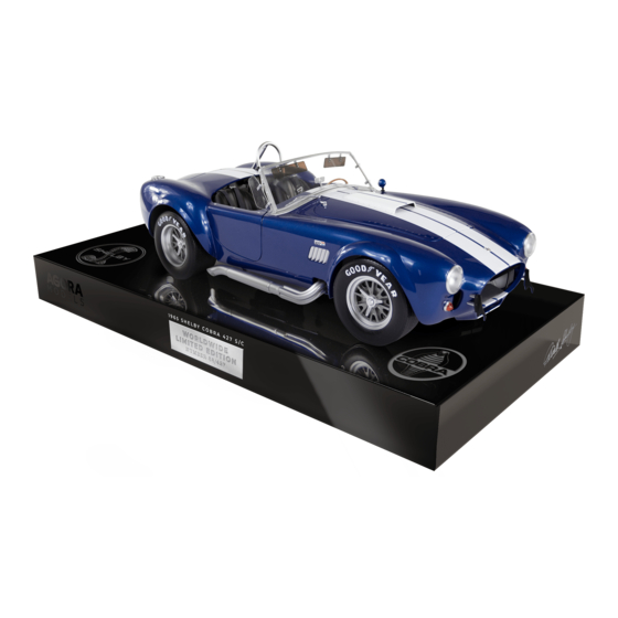
Your 1:8 model replicates the original 1965 Semi-Competition Cobra in intricate detail. From the detail on
the dashboard dials to the writing on the wheels, every piece is precisely reproduced.
STAGE 41: DASHBORD SWITCHES AND
STEERING ROD GUIDE
STAGE 42: DASHBOARD DIALS
AND SWITCH
STAGE 43: CENTER CONSOLE AND
LEFT FLOOR SECTION
STAGE 44: RIGHT FLOOR SECTION
AND FLOOR MATS
AGORAMODELS
Pack 06 | Build Instructions
sought-after American sports cars by collectors.
In your sixth model pack, you will assemble:
STAGE 45: COCKPIT REAR WALL
STAGE 46: GEAR LEVER,
HANDBRAKE AND U-BAR
STAGE 47: ACCELERATOR PEDAL & SWITCH,
BRAKE PEDAL & SWITCH, CLUTCH PEDAL ,
FLOOR PLATE
STAGE 4 8: MOUNTING BOX
AND MAIN SWITCH
1
SHELBY COBRA 427 S/C
Advertisement

Subscribe to Our Youtube Channel
Related Manuals for Agora Models SHELBY COBRA 427 SEMI-COMPETITION 1965


Summary of Contents for Agora Models SHELBY COBRA 427 SEMI-COMPETITION 1965
- Page 1 Pack 06 | Build Instructions In the 1960s, Carroll Shelby’s Cobras dominated racetracks worldwide, first winning races coast to coast across North America, then in 1965, winning the World Manufacturer’s GT Championship, achieving the ultimate goal of defeating Ferrari. The Semi-Competitions were modified from full competition models just enough to make them street legal.
- Page 2 Stage 41: Dashbord Switches and Steering Rod Guide In this first stage of building the Shelby Cobra, you will assemble the dashboard. S T A G E 4 1 P A R T S L I S T Name Quantity Dashboard Main Panel Dashboard Button Line 1 Dashboard Button Line 2...
- Page 3 Stage 41: Dashbord Switches and Steering Rod Guide S T E P 1 A T T A C H T H E D A S H B O A R D P L A T E S A N D S T E E R I N G R O D G U I D E With the reverse side of the Dashboard Main Panel facing you, place the Dashboard Plate 1...
- Page 4 Stage 41: Dashbord Switches and Steering Rod Guide C O N T I N U E D . . . Turn the Main Panel over so the front side is facing you and place the Dashboard Plate 3 into position. Fix from the reverse side using a TYPE OP08 screw.
- Page 5 Stage 41: Dashbord Switches and Steering Rod Guide S T E P 2 A T T A C H T H E D A S H B O A R D S W I T C H E S Take the Dashboard Button Line 1 and remove the button shown. Push into position on the Main Panel as shown in picture 3.
- Page 6 Stage 41: Dashbord Switches and Steering Rod Guide AGORAMODELS SHELBY COBRA 427 S/C...
- Page 7 Stage 41: Dashbord Switches and Steering Rod Guide Stage 41 complete! AGORAMODELS SHELBY COBRA 427 S/C...
- Page 8 Stage 42: Dashbord Dials and Switch In stage 42, you will assemble the dashboard dials. S T A G E 4 2 P A R T S L I S T Name Quantity Dial Board Push Button Switch Chrome Dial Surround Dial Lenses Board Dial Holding Plate Dial Stickers...
- Page 9 Stage 42: Dashbord Dials and Switch S T E P 1 A S S E M B L E T H E D A S H B O A R D D I A L S Peel the dashboard Dial Stickers from the sticker sheet and position them on the Dial Board in the positions shown.
- Page 10 Stage 42: Dashbord Dials and Switch C O N T I N U E D . . . Then sandwich the lenses in place by placing the Dial Board on top, squeezing them together to fix. Next, take the Dial Holding Plate (picture 7) and position the Switch with cable 03 as shown.
- Page 11 Stage 42: Dashbord Dials and Switch C O N T I N U E D . . . Then align the chrome plate on the Dial Lenses assembly with the Main Panel from the previous stage. The central tab on the Main Panel extends into the notch on the dials (arrows - picture 12).
- Page 12 Stage 42: Dashbord Dials and Horn Switch Stage 42 complete! AGORAMODELS SHELBY COBRA 427 S/C...
- Page 13 Stage 43: Center Console and Left Floor Section Now the dashboard is complete, you will start to assemble the floor sections. S T A G E 4 3 P A R T S L I S T Name Quantity Center Console Left Floor Part Electrical Wire Holder Screws TYPE OP08...
- Page 14 Stage 43: Center Console and Left Floor Section S T E P 1 A S S E M B L E T H E F L O O R Place the Center Console on your worksurface with the reverse side facing up and align the screw holes on the Left Floor Part.
- Page 15 Stage 43: Center Console and Left Floor Section Stage 43 complete! AGORAMODELS SHELBY COBRA 427 S/C...
- Page 16 Stage 44: Right Floor Section and Floor Mats In stage 44, you will continue to assemble the floor. S T A G E 4 4 P A R T S L I S T Name Quantity Right Floor Part Driver’s Floor Mat Passenger’s Floor Mat Screws TYPE OP08 Right Floor Part...
- Page 17 Stage 44: Right Floor Section and Floor Mats S T E P 1 A S S E M B L E T H E F L O O R A N D F I X T H E F L O O R M A T S Align the screw holes on the Right Floor Part with the opposite side of the Center Console, just as in the previous stage.
- Page 18 Stage 44: Right Floor Section and Floor Mats Stage 44 complete! AGORAMODELS SHELBY COBRA 427 S/C...
- Page 19 Stage 45: Cockpit Rear Wall In stage 45, you will add the rear wall of the cockpit to the floor. S T A G E 4 5 P A R T S L I S T Name Quantity Cockpit Rear Wall Screws TYPE OP08 Cockpit Rear Wall Screws...
- Page 20 Stage 45: Cockpit Rear Wall S T E P 1 A T T A C H T H E R E A R W A L L Take the Cockpit Rear Wall and align the four- tabs-with-screwholes with the corresponding holes on the floor assembly.
- Page 21 Stage 46: Gear Lever, Handbrake and U-Bar In stage 46, you will add the gear lever, hand brake and U-bar S T A G E 4 6 P A R T S L I S T Name Quantity Gear Lever Gear Lever Knob Gear Lever Boot Gear Lever Bracket...
- Page 22 Stage 46: Gear Lever, Handbrake and U-Bar S T E P 1 A S S E M B L E T H E G E A R L E V E R B O O T & B R A C K E T Align the two little pins on the Boot with the two little holes in the Bracket.
- Page 23 Stage 46: Gear Lever, Handbrake and U-Bar S T E P 2 A T T A C H T H E U - B A R Push the ends of the U-bar into the holes in the Center Console and fix in place from the reverse side using 2 x TYPE OP08 screws.
- Page 24 Stage 46: Gear Lever, Handbrake and U-Bar S T E P 3 A S S E M B L E & A T T A C H T H E G E A R L E V E R Push-fit the Gear Lever Knob to the Gear Lever. The knob has a D shaped hole to ensure that the numbers are correct.
- Page 25 Stage 46: Gear Lever, Handbrake and U-Bar Stage 46 complete! AGORAMODELS SHELBY COBRA 427 S/C...
- Page 26 Stage 47: Accelerator Pedal & Switch, Brake Pedal & Switch, Clutch Pedal, Floor Plate In stage 47, you will attach the pedals and electrical switches. S T A G E 4 7 P A R T S L I S T Name Quantity Accelerator Push Button Switch 05...
- Page 27 Stage 47: Accelerator Pedal & Switch, Brake Pedal & Switch, Clutch Pedal, Floor Plate S T E P 1 A T T A C H T H E P E D A L F L O O R P L A T E A N D P E D A L S Push-fit the Pedal Floor Plate onto the floor assembly in the position shown.
- Page 28 Stage 47: Accelerator Pedal & Switch, Brake Pedal & Switch, Clutch Pedal, Floor Plate C O N T I N U E D . . . Push the two lugs on the Brake Pedal into the small holes on the Plate. Fix in place from the reverse using 1 x TYPE OP10 screw.
- Page 29 Stage 47: Accelerator Pedal & Switch, Brake Pedal & Switch, Clutch Pedal, Floor Plate S T E P 2 F I X T H E E L E C T R I C A L W I R E S Push-fit the Switch 02 into one of the Switch Holders.
- Page 30 Stage 47: Accelerator Pedal & Switch, Brake Pedal & Switch, Clutch Pedal, Floor Plate C O N T I N U E D . . . Repeat by push-fitting Switch 05 into the second Switch Holder and fix to the reverse side of the Cockpit Rear Wall using another TYPE OP08 screw.
- Page 31 Stage 47: Accelerator Pedal & Switch, Brake Pedal & Switch, Clutch Pedal, Floor Plate C O N T I N U E D . . . Secure Cable 02 to the underside of the floor using two Cable Holders as shown. The Cable Holders push-fit into place.
- Page 32 Stage 48: Mounting Box and Main Switch In stage 48, you will attach the main switch and fix the mounting box to the chassis. S T A G E 4 8 P A R T S L I S T Name Quantity Mounting Box...
- Page 33 Stage 48: Mounting Box and Main Switch S T E P 1 F I X T H E M A I N S W I T C H Take the Main Switch 04 and connect it to the socket in the Center Console as shown. Lower the Main Switch 04 Holder on top of the socket to hold the switch in place and fix with a TYPE OP02 screw.
- Page 34 Stage 48: Mounting Box and Main Switch S T E P 2 A S S E M B L E A N D A T T A C H T H E M O U N T I N G B O X Push-fit Pipe 1 and Pipe 2 to the Mounting Box as shown.
- Page 35 Stage 48: Mounting Box and Main Switch C O N T I N U E D . . . Once in position, turn the chassis over so it's the right way up and fix the Mounting Box in place using 2 x TYPE OP01 screws. Slide the Mounting Box Cover onto the box.
- Page 36 Stage 48: Mounting Box and Main Switch S T E P 3 F I X T H E C A B L E H O L D E R Finally, position the Cable Holder on the floor panels to secure Cable 01 in place. This is a push fit so press firmly.
Need help?
Do you have a question about the SHELBY COBRA 427 SEMI-COMPETITION 1965 and is the answer not in the manual?
Questions and answers