Table of Contents
Advertisement
Quick Links
Pack 04 | Build Instructions
Your Shelby GT500 Super Snake is a finely detailed model replicating
every aspect of the original car. From the paint colour to the smallest
interior details, every piece is precisely reproduced.
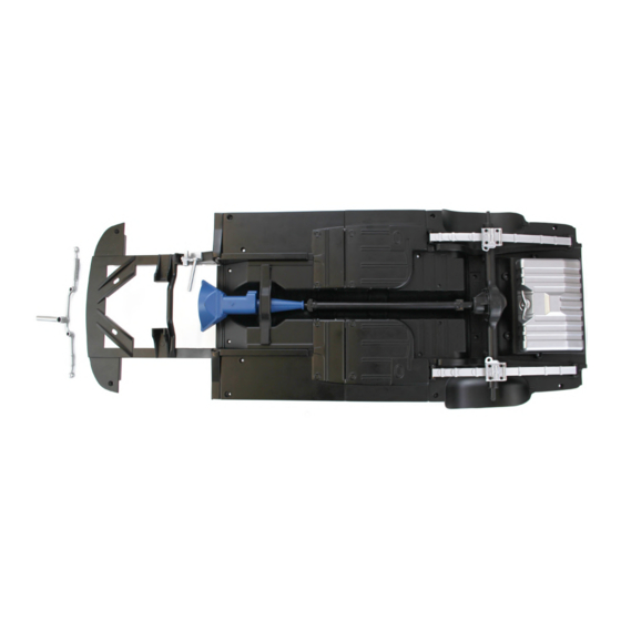
In your fourth model pack, you will assemble:
STAGE 23: MIDDLE CHASSIS
STAGE 28: FRONT FENDER SPLASH GUARDS
STAGE 24: FRONT FLOOR PAN
STAGE 29: TIE ROD ASSEMBLY
Tie Rods and Center Link
STAGE 25: DRIVESHAFT
STAGE 30: STEERING ASSEMBLY
STAGE 26: GEARBOX AND CROSSMEMBER
Steering Gear, Pitman Arm and
STAGE 27: FRONT CHASSIS
Suspenion Arm Mounts
1
AGORAMODELS
SHELBY SUPER SNAKE
Advertisement
Table of Contents

Subscribe to Our Youtube Channel
Related Manuals for Agora Models Shelby GT500 1967 Super Snake


Summary of Contents for Agora Models Shelby GT500 1967 Super Snake
- Page 1 Pack 04 | Build Instructions Your Shelby GT500 Super Snake is a finely detailed model replicating every aspect of the original car. From the paint colour to the smallest interior details, every piece is precisely reproduced. In your fourth model pack, you will assemble: STAGE 23: MIDDLE CHASSIS STAGE 28: FRONT FENDER SPLASH GUARDS STAGE 24: FRONT FLOOR PAN...
- Page 2 Stage 23: Middle Chassis Your fourth Pack starts with connecting the Middle Chassis to the Rear Main Chassis Assembly. S T A G E 2 3 P A R T S L I S T Name Quantity Middle Chassis Screws TYPE MD06 5 [inc.
- Page 3 Stage 23: Middle Chassis S T E P 1 A T T A C H T H E M I D D L E C H A S S I S T O T H E R E A R M A I N C H A S S I S A S S E M B LY Take the Rear Chassis Assembly that you assembled in Stage 22.
- Page 4 Stage 23: Middle Chassis Stage 23 complete! AGORAMODELS SHELBY SUPER SNAKE...
- Page 5 Stage 24: Front Floor Pan Now you are going to connect the Front Floor Pan to the Chassis Assembly. S T A G E 2 4 P A R T S L I S T Name Quantity Front Floor Pan Screws TYPE MD02 5 (inc.
- Page 6 Stage 24: Front Floor Pan P L E A S E N O T E Only loosely connect the Floor Pan for now – do not tighten the screws. The Floor Pan will have to be removed later to enable the exhaust pipes to be attached. S T E P 1 A T T A C H T H E F R O N T F L O O R P A N T O T H E C H A S S I S A S S E M B LY...
- Page 7 Stage 24: Front Floor Pan F I N I S H S E C U R I N G T H E F L O O R P A N T O T H E C H A S S I S Make sure the tabs are flush with the chassis, then place 4 x TYPE MD02 screws in the anchor points indicated in picture 4.
- Page 8 Stage 24: Front Floor Pan Stage 24 complete! AGORAMODELS SHELBY SUPER SNAKE...
- Page 9 Stage 25: Driveshaft In this stage you will assemble the Driveshaft and attach it to the Chassis Assembly. S T A G E 2 5 P A R T S L I S T Name Quantity Driveshaft upper half Driveshaft lower half Screws TYPE MP01 3 (inc.
- Page 10 Stage 25: Driveshaft S T E P 1 A S S E M B L E T H E D R I V E S H A F T Take the two halves of the driveshaft and, with the flat side of each facing one another, press together so that they’re flush.
- Page 11 Stage 25: Driveshaft S T E P 2 A T T A C H T H E D R I V E S H A F T T O T H E C H A S S I S Take the Chassis Assembly. Insert the T-shaped end of the Driveshaft into the differential housing whilst also ensuring the lugs on the upper half of the Driveshaft fit into the two...
- Page 12 Stage 26: Gearbox and Crossmember Now you are going to connect the Gearbox to the Chassis Assembly S T A G E 2 6 P A R T S L I S T Name Quantity Gearbox Gearbox Crossmember Screws TYPE MP01 (5 inc.
- Page 13 Stage 26: Gearbox and Crossmember S T E P 1 F I T T H E G E A R B O X T O T H E C H A S S I S A S S E M B LY On the upper side of the Gearbox, you’ll find two mounting lugs which correspond to the two holes in the Chassis Assembly.
- Page 14 Stage 26: Gearbox and Crossmember S T E P 2 A T T A C H T H E C R O S S M E M B E R With the Gearbox now in place, turn the Chassis Assembly back over so you are working on the underside of the Chassis.
- Page 15 Stage 27: Front Chassis In this stage, you will connect the Front Chassis to the Chassis Assembly S T A G E 2 7 P A R T S L I S T Name Quantity Front Chassis Screws TYPE MD06 5 (inc.
- Page 16 Stage 27: Front Chassis S T E P 1 C O N N E C T T H E F R O N T C H A S S I S T O T H E C H A S S I S A S S E M B LY Position the Front Chassis over the Chassis Assembly as shown, ensuring that the four, rearmost raised lugs on the Front Chassis...
- Page 17 Stage 27: Front Chassis Stage 27 complete! AGORAMODELS SHELBY SUPER SNAKE...
- Page 18 Stage 28: Front Fender Splash Guards You are now going to connect the Front Fender Splash Guards to the Chassis Assembly. S T A G E 2 8 P A R T S L I S T Name Quantity Right Front Fender Splash Guard Left Front Fender Splash Guard Screws TYPE MD06 5 (inc.
- Page 19 Stage 28: Front Fender Splash Guards S T E P 1 C O N N E C T T H E L E F T A N D R I G H T F R O N T F E N D E R S P L A S H G U A R D S T O T H E C H A S S I S A S S E M B LY Position the two Front Fender Splash Guards next to the Chassis Assembly, paying...
- Page 20 Stage 29: Steering Rods Now you are going to connect the Steering Rods together to form the Tie Rod Assembly. S T A G E 2 9 P A R T S L I S T Name Quantity Left Tie Rod Right Tie Rod Center Link Screws TYPE MD06...
- Page 21 Stage 29: Steering Rods S T E P 1 C O N N E C T T H E S T E E R I N G R O D S T O G E T H E R Position the Right Tie Rod and Center Link as shown in the picture.
- Page 22 Stage 29: Steering Rods Stage 29 complete! AGORAMODELS SHELBY SUPER SNAKE...
- Page 23 Stage 30: Steering and Suspension Components Now you are going to assemble parts connected to the steering and suspension. S T A G E 3 0 P A R T S L I S T Name Quantity Suspension Arm Mounts Steering Gear Pitman Arm Screws TYPE MD06...
- Page 24 Stage 30: Steering and Suspension Components S T E P 1 A T T A C H T H E S U S P E N S I O N A R M M O U N T S Place the Chassis Assembly upside down on your worktable, locate the two openings on the side spars on the front of the Front Chassis, as shown in the picture.
- Page 25 Stage 30: Steering and Suspension Components S T E P 3 Take the Tie Rod Assembly from the previous stage. Locate the lug on the Center Link, and place the narrow end of the opening on the Pitman Arm on this lug. Secure it in place with an MD02 screw, tightening only so much that the arm can still move freely.
Need help?
Do you have a question about the Shelby GT500 1967 Super Snake and is the answer not in the manual?
Questions and answers