Advertisement
Quick Links
Converter with Power System Management
DESCRIPTION
Demonstration circuit 2881A-A is a 2-phase dual-output,
high efficiency, high density, synchronous buck converter
with 7V to 14V input range. Each output can supply up
to 30A maximum load current with 1V output. The demo
board features the
LTC
3884-1
®
LTC7050
dual smart power stage to provide a 2-phase
buck converter solution. The LTC3884-1 is a dual output
poly phase step-down controller with digital power sys-
tem management. The LTC7050 is a dual monolithic smart
power stage which integrates high speed drivers with low
resistance half-bridge power switches plus comprehensive
monitoring and protection circuitry in an electrically and
thermally optimized package. Please refer to the LTC3884-1
and LTC7050 data sheet for more detailed information.
DC2881A-A powers up to default settings and produces
power based on configuration resistors (or with the
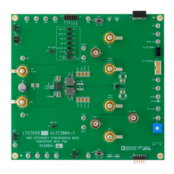
BOARD PHOTO
2-Phase, Dual-Output Synchronous Buck
controller paired with the
Figure 1. Dual-Output LTC7050 + LTC3884-1/DC2881A-A Demo Circuit
DEMO MANUAL DC2881A-A
LTC7050/LTC3884-1
setting in its non-volatile memory) without the need for
any serial bus communication. This allows easy evalua-
tion of the DC/DC converter. To fully explore the extensive
power system management features of the part, download
the GUI software LTpowerPlay
2
ADI's I
C/SMBus/PMBus dongle DC1613A to connect to
the board. LTpowerPlay allows the user to reconfigure the
part on the fly and store the configuration in EEPROM, view
telemetry of voltage, current, temperature and fault status.
GUI Download
The software can be downloaded from here.
For more details and instructions of LTpowerPlay, please
refer to LTpowerPlay Quick Start Procedure.
Design files for this circuit board are
All registered trademarks and trademarks are the property of their respective owners.
onto your PC and use
®
available.
Rev. 0
1
Advertisement

Related Manuals for Analog Devices DC2881A-A


Summary of Contents for Analog Devices DC2881A-A
- Page 1 For more details and instructions of LTpowerPlay, please and LTC7050 data sheet for more detailed information. refer to LTpowerPlay Quick Start Procedure. DC2881A-A powers up to default settings and produces Design files for this circuit board are available. power based on configuration resistors (or with the All registered trademarks and trademarks are the property of their respective owners.
-
Page 2: Quick Start Procedure
OUT1/2 OUT1/2 Default Switching Frequency QUICK START PROCEDURE DC2881A-A is easy to set up to evaluate the performance • SW1 RUN1: ON of LTC7050 and LTC3884-1. Refer to Figure 2 for the • SW2 RUN2: ON proper measurement equipment setup and follow the 5. - Page 3 DEMO MANUAL DC2881A-A OUTPUT AND ONBOARD E-LOAD CONFIGURATION the load current step. The maximum load current step load current will follow the slew rate of EXT PULSE lin- achievable is typically 25A. The dynamic circuit MOSFET early. Refer to the table in the schematic file to optimally is off when EXT PULSE is floating or grounded.
- Page 4 DEMO MANUAL DC2881A-A OUTPUT AND ONBOARD E-LOAD CONFIGURATION Connecting a PC to DC2881A-A points, OV/UV limits, temperature fault limits, sequenc- ing parameters, the fault log, fault responses, GPIOs You can use a PC to reconfigure the power management and other functionalities. The DC1613A dongle may be...
- Page 5 DEMO MANUAL DC2881A-A OUTPUT AND ONBOARD E-LOAD CONFIGURATION – OUT1 – – POWER – SUPPLY OUT1 – LOAD1 dc2881a-a F05 Figure 5. Measuring Setup for DC2881 Efficiency Rev. 0...
- Page 6 DEMO MANUAL DC2881A-A OUTPUT AND ONBOARD E-LOAD CONFIGURATION – POWER OUT1 SUPPLY – – – POWER – SUPPLY OUT1 – LOAD1 – – dc2881a-a F06 POWER POWER SUPPLY SUPPLY – Figure 6. Measuring Setup for LTC7050 Efficiency Rev. 0...
- Page 7 DEMO MANUAL DC2881A-A OUTPUT AND ONBOARD E-LOAD CONFIGURATION DC2881 V Efficiency vs Load at LTC7050 V Efficiency vs Load at OUT1/2 OUT1/2 = 12V, f = 500kHz, 1-Phase = 12V, f = 500kHz, 1-Phase = 1V = 1V = 1.8V = 1.8V...
- Page 8 DEMO MANUAL DC2881A-A OUTPUT AND ONBOARD E-LOAD CONFIGURATION OUT2 OUT1 (20MHz BW) (20MHz BW) 20mV/DIV 20mV/DIV dc2881a-a F11 dc2881a-a F12 2µs/DIV 2µs/DIV Figure 11. V Voltage Ripple = 17.4mV at Figure 12. V Voltage Ripple = 17.4mV at OUT1 OUT2 = 12V, V...
- Page 9 The software supports a variety of different tasks. You LTC3882, LTC3883, LTC3884 and LTC3888-1’s demo can use LTpowerPlay to evaluate Analog Devices ICs by system, or a customer board. The software also provides connecting to a demo board system. LTpowerPlay can...
- Page 10 1. Download and install the LTpowerPlay GUI from here. 2. Launch the LTpowerPlay GUI. a. The GUI should automatically identify the DC2881A-A. The system tree on the left hand side should look like this: d. If you want to change the output voltage to a different value, like 1.2V.
-
Page 11: Parts List
DEMO MANUAL DC2881A-A LTpowerPlay QUICK START PROCEDURE If the write is successful, you will see the following e. You can save the changes into the NVM. In the tool bar, message: click RAM to NVM button, as following f. Save the demo board configuration to a (*.proj) file. - Page 12 DEMO MANUAL DC2881A-A PARTS LIST ITEM REFERENCE PART DESCRIPTION MANUFACTURER/PART NUMBER Q7, Q8 XSTR., MOSFET, N-CH, 60V, 220mA, SOT23-3, AEC-Q101 DIODES INC., 2N7002A-13 XSTR., MOSFET, N-CH, 30V, 90A, TO-252-3 (DPAK) INFINEON, IPD90N03S4L-02 RES., 0.001Ω, 1%, 1W, 2512, METAL, SENSE, AEC-Q200...
- Page 13 DEMO MANUAL DC2881A-A PARTS LIST ITEM REFERENCE PART DESCRIPTION MANUFACTURER/PART NUMBER Additional Demo Board Circuit Components C5, C9, C16, C26, C192, C210, CAP ., OPTION, 0603 C211, COUT26, COUT37 C27, C28 CAP ., 0.01µF, X7R, 25V, 10%, 0603, AEC-Q200 AVX, 06033C103K4Z2A C34, C35 CAP ., 4.7µF, X5R, 16V, 20%, 1210...
- Page 14 DEMO MANUAL DC2881A-A PARTS LIST ITEM REFERENCE PART DESCRIPTION MANUFACTURER/PART NUMBER RES., 0.01Ω, 1%, 1W, 2512, PWR, METAL, SENSE, VISHAY, WSL2512R0100FEA AEC-Q200 R88, R158 RES., OPTION, 0805 R69, R70 RES., 10Ω, 1%, 1/10W, 0603 VISHAY, CRCW060310R0FKEA R128, R150 RES., 4.99k, 1%, 1/10W, 0603...
-
Page 15: Schematic Diagram
DEMO MANUAL DC2881A-A SCHEMATIC DIAGRAM Rev. 0... - Page 16 DEMO MANUAL DC2881A-A SCHEMATIC DIAGRAM Rev. 0...
- Page 17 Devices for its use, nor for any infringements of patents or other rights of third parties that may result from its use. Specifications subject to change without notice. No license is granted by implication or otherwise under any patent or patent rights of Analog Devices.
- Page 18 Board until you have read and agreed to the Agreement. Your use of the Evaluation Board shall signify your acceptance of the Agreement. This Agreement is made by and between you (“Customer”) and Analog Devices, Inc. (“ADI”), with its principal place of business at One Technology Way, Norwood, MA 02062, USA. Subject to the terms and conditions of the Agreement, ADI hereby grants to Customer a free, limited, personal, temporary, non-exclusive, non-sublicensable, non-transferable license to use the Evaluation Board FOR EVALUATION PURPOSES ONLY.
Need help?
Do you have a question about the DC2881A-A and is the answer not in the manual?
Questions and answers