Advertisement
Quick Links
Converter with Power System Management
DESCRIPTION
Demonstration circuit 2652A-A is an 8-phase dual-output,
high efficiency, high density, synchronous buck converter
with 7V to 14V input range. Each output can supply up to
120A maximum load current with 1V output. The demo
board showcases the
LTC
compliant dual loop 8-phase step-down DC/DC controller
with digital power system management. The LTC3888 is
designed to work with DrMOS devices that provide an out-
put current sense and temperature monitor. Please refer
to LTC3888's data sheet for more detailed information.
DC2652A-A powers up to default settings and produces
power based on configuration resistors (or with the set-
ting in its non-volatile memory) without the need for any
serial bus communication. This allows easy evaluation of
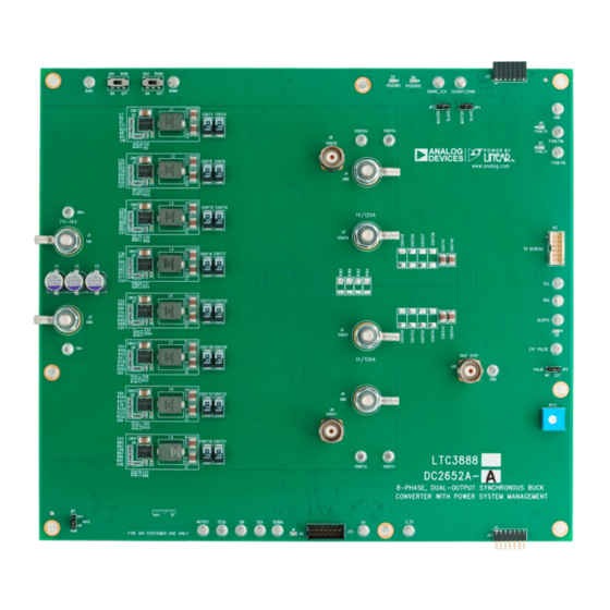
BOARD PHOTO
8-Phase, Dual-Output Synchronous Buck
3888, which is a PMBus-
®
Figure 1. Dual-Output LTC3888/DC2652A-A Demo Circuit
DEMO MANUAL DC2652A-A
the DC/DC converter. To fully explore the extensive power
system management features of the part, download the
GUI software LTpowerPlay™ onto your PC and use ADI's
2
I
C/SMBus/PMBus dongle DC1613A to connect to the
board. LTpowerPlay allows the user to reconfigure the part
on the fly and store the configuration in EEPROM, view
telemetry of voltage, current, temperature and fault status.
GUI Download
The software can be downloaded from:
here
For more details and instructions of LTpowerPlay,
please refer to LTpowerPlay Quick Start Procedure.
Design files for this circuit board are
All registered trademarks and trademarks are the property of their respective owners.
LTC3888
available.
Rev. 0
1
Advertisement

Subscribe to Our Youtube Channel
Related Manuals for Analog Devices DC2652A-A


Summary of Contents for Analog Devices DC2652A-A
- Page 1 The software can be downloaded from: to LTC3888’s data sheet for more detailed information. here DC2652A-A powers up to default settings and produces For more details and instructions of LTpowerPlay, power based on configuration resistors (or with the set- please refer to LTpowerPlay Quick Start Procedure.
-
Page 2: Performance Summary
OUT1 Default Switching Frequency 500kHz QUICK START PROCEDURE DC2652A-A is easy to set up to evaluate the performance Note: of LTC3888. Refer to Figure 2 for the proper measurement 1. When measuring the efficiency, it is recommended equipment setup and follow the procedure below. - Page 3 DEMO MANUAL DC2652A-A QUICK START PROCEDURE – OUT0 – LOAD0 – – OUT0 POWER SUPPLY – – – OUT1 LOAD1 – – OUT1 DC2652A-A F02 Figure 2. Proper Measurement Equipment Setup – Figure 3. Measuring Output Voltage Ripple Rev. 0...
- Page 4 DEMO MANUAL DC2652A-A QUICK START PROCEDURE Connecting a PC to DC2652A-A points, OV/UV limits, temperature fault limits, sequenc- ing parameters, the fault log, fault responses, GPIOs You can use a PC to reconfigure the power management and other functionalities. The DC1613A dongle may be...
- Page 5 DEMO MANUAL DC2652A-A QUICK START PROCEDURE OUT0 (20MHz BW) OUT1 [50mV/DIV] (20MHz BW) [50mV/DIV] 0A-30A 0A-30A OUT0 OUT1 LOAD STEP LOAD STEP [20A/DIV] [20A/DIV] DC2652A-A F07 DC2652A-A F08 100µs/DIV 100µs/DIV Figure 7. V Load Transient Response at Figure 8. V Load Transient Response at...
- Page 6 DEMO MANUAL DC2652A-A QUICK START PROCEDURE Figure 11. Thermal at V = 12V, V = 1.0V, I = 120A, V = 1.0V, I = 120A, T = 23°C, No Airflow OUT0 OUT0 OUT1 OUT1 Rev. 0...
- Page 7 The software supports a variety of different tasks. You tem, or a customer board. The software also provides an can use LTpowerPlay to evaluate Analog Devices ICs by automatic update feature to keep the software current with connecting to a demo board system. LTpowerPlay can the latest set of device drivers and documentation.
- Page 8 1 Download and install the LTpowerPlay GUI: here 2. Launch the LTpowerPlay GUI. a. The GUI should automatically identify the DC2652A-A. The system tree on the left hand side should look like this: Then, click the “W” (PC to RAM) icon to write these register values to the LTC3888.
-
Page 9: Parts List
DEMO MANUAL DC2652A-A PARTS LIST ITEM REFERENCE PART DESCRIPTION MANUFACTURER/PART NUMBER Required Circuit Components C1, C2, C3, C4, C5, C6 CAP ., 270µF, ALUM, 16V, 20%, SMD 8 × 11.9mm, PANASONIC/16SVPC270M COUT1, COUT2, COUT6, COUT7, CAP ., 100µF, X5R, 6.3V, 20%, 1210... - Page 10 DEMO MANUAL DC2652A-A PARTS LIST ITEM REFERENCE PART DESCRIPTION MANUFACTURER/PART NUMBER RES., 1Ω, 5%, 1/10W, 0603, AEC-Q200 VISHAY/CRCW06031R00JNEA R9, R10, R18 RES., 1kΩ, 1%, 1/10W, 0603, AEC-Q200 NIC/NRC06F1001TRF R15, R17, R48, R49, R51, R54, R244 RES.,10kΩ, 1%, 1/10W, 0603, AEC-Q200 KOA SPEER/RK73H1JTTD1002F RES., 4.99kΩ, 1%, 1/10W, 0603, AEC-Q200...
- Page 11 DEMO MANUAL DC2652A-A PARTS LIST ITEM REFERENCE PART DESCRIPTION MANUFACTURER/PART NUMBER D4, D5 LED, GREEN, WATER CLEAR, 0603 Wurth/150060GS75000 D6, D7, D8 LED, SUPER RED, WATERCLEAR, 0603 Wurth/150060SS75000 LED, SUPER RED, WATERCLEAR, 0603 Wurth/150060SS75000 D10, D11, D12, D13, D14, D15 DIODE, SCHOTTKY, 20V, 0.5A, SOD-882,...
- Page 12 DEMO MANUAL DC2652A-A PARTS LIST ITEM REFERENCE PART DESCRIPTION MANUFACTURER/PART NUMBER R174 RES., 82.5Ω, 1%, 1/10W, 0603, AEC-Q200 NIC/NRC06F82R5TRF R175 RES., 5kΩ, 10%, 1/2W, THT 3/8" SQ, 1-TURN, BOURNS/3386P-1-502LF TOP ADJ., TRIMPOT R176 RES., OPTION, 2512 R177 RES., 0.01Ω, 1%, 1W, 2512, PWR, METAL,...
- Page 13 DEMO MANUAL DC2652A-A PARTS LIST ITEM REFERENCE PART DESCRIPTION MANUFACTURER/PART NUMBER Hardware: For Demo Board Only XJP1, XJP2, XJP3, XJP4 CONN., SHUNT, FEMALE, 2 POS, 2mm Wurth/60800213421 MP1, MP2, MP3, MP4, MP5, MP6, STANDOFF , NYLON, SNAP-ON, 0.50" Wurth/702935000 MP7, MP8 E1, E2, E3, E4, E5, E6, E7, E8, E9, TEST POINT, TURRET, 0.094"...
- Page 14 DEMO MANUAL DC2652A-A SCHEMATIC DIAGRAM Rev. 0...
- Page 15 DEMO MANUAL DC2652A-A SCHEMATIC DIAGRAM Rev. 0...
- Page 16 DEMO MANUAL DC2652A-A SCHEMATIC DIAGRAM Rev. 0...
-
Page 17: Schematic Diagram
DEMO MANUAL DC2652A-A SCHEMATIC DIAGRAM Rev. 0... - Page 18 DEMO MANUAL DC2652A-A SCHEMATIC DIAGRAM Rev. 0...
- Page 19 DEMO MANUAL DC2652A-A SCHEMATIC DIAGRAM Rev. 0...
- Page 20 DEMO MANUAL DC2652A-A SCHEMATIC DIAGRAM Rev. 0...
- Page 21 Devices for its use, nor for any infringements of patents or other rights of third parties that may result from its use. Specifications subject to change without notice. No license is granted by implication or otherwise under any patent or patent rights of Analog Devices.
- Page 22 Board until you have read and agreed to the Agreement. Your use of the Evaluation Board shall signify your acceptance of the Agreement. This Agreement is made by and between you (“Customer”) and Analog Devices, Inc. (“ADI”), with its principal place of business at One Technology Way, Norwood, MA 02062, USA. Subject to the terms and conditions of the Agreement, ADI hereby grants to Customer a free, limited, personal, temporary, non-exclusive, non-sublicensable, non-transferable license to use the Evaluation Board FOR EVALUATION PURPOSES ONLY.
Need help?
Do you have a question about the DC2652A-A and is the answer not in the manual?
Questions and answers