Table of Contents
Advertisement
Quick Links
Bulletin MSG11-5715-734/UK
Operation Manual
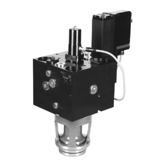
Series TFP
Design ≥ 12
2-Way Servo
Proportional Valves with
®
VCD
-Technology
Parker Hannifin
Manufacturing Germany GmbH & Co. KG
Industrial Systems Division Europe
Gutenbergstr. 38
41564 Kaarst, Germany
E-mail: isde.kaarst.support@support.parker.com
Copyright © 2022, Parker Hannifin Corp.
Advertisement
Table of Contents

Related Manuals for Parker TFP Series


Summary of Contents for Parker TFP Series
- Page 1 Bulletin MSG11-5715-734/UK Operation Manual Series TFP Design ≥ 12 2-Way Servo Proportional Valves with ® -Technology Parker Hannifin Manufacturing Germany GmbH & Co. KG Industrial Systems Division Europe Gutenbergstr. 38 41564 Kaarst, Germany E-mail: isde.kaarst.support@support.parker.com Copyright © 2022, Parker Hannifin Corp.
- Page 2 The user must analyze all aspects of the application, follow applicable industry standards, and follow the information concerning the product in the current product catalog and in any other materials provided from Parker or its subsidiaries or authorized distributors.
-
Page 3: Table Of Contents
Limits of Use Pressure Fluids Electrical Connection Electrical Interfacing 5. Operation Instructions Solenoid Current Monitoring ProPxD Parameterizing Software Air Bleeding of Hydraulic System Filter Flushing 6. Troubleshooting 7. Accessories / Spare Parts Accessories Spare Parts TFP 5715-734UK.indd 24.06.22 Parker Hannifin Corporation... -
Page 4: Introduction
Operation Manual Series TFP 1. Introduction ® Parker 2-way servo proportional valves with VCD technology have an integrated electronics and re- quire only one sole electrical common for the control system. Different flow sizes are available to achieve an optimal adaption for different applications. -
Page 5: Order Code Tfp
X1 (00) and Y1 (99) Note : Please order connector separately HFC fluids suitable. For DFplus pilot valve with EtherCAT interface see installation " manual MSG11-5715-708/UK, Supplement for Valves with " EtherCAT Interface TFP 5715-734UK.indd 24.06.22 Parker Hannifin Corporation... -
Page 6: Technical Data
Please also consider the Parker accumulator product switching element with sufficient reliability. range and the Parker Accumulator Sizing Software. -
Page 7: Block Diagram Of Integral Electronics
6 + PE acc. EN 175201-804 Wiring min. [mm²] 7 x 1.0 (AWG16) overall braid shield Wiring lenght max. [m] 50 Block Diagram of Integrated Electronics Do not connect with the supply voltage zero. TFP 5715-734UK.indd 24.06.22 Parker Hannifin Corporation... -
Page 8: Safety Instructions
This manual uses symbols which have to be fol- lowed accordingly: Do not disassemble the valve! In case of suspicion for a defect please contact Parker. Instructions with regard to the warranty Storage Instructions with regard to possible... -
Page 9: Available Bolts Kits
SW6 (TFP050: the two ring bolts) with the disas- ly. By turning them against the straps, the valve is sembly aids and turn the straps 90° against the pulled out of the cavity. 90° TFP 5715-734UK.indd 24.06.22 Parker Hannifin Corporation... -
Page 10: Limits Of Use
50 m For detailed information concerning pressure fluids note VDMA-document 24317 as well as For cable lengths > 50 m consult Parker. DIN 51524 & 51502. Special gaskets may be available depending on The connection cable is coupled to the female the utilized fluid. -
Page 11: Electrical Interfacing
It is necessary to use valve respectively incorporated system parts. a low ohmic potential connection between control unit and machine frame to prevent earth loops (cross section AWG 6). Wiring Diagram of Supply Voltage TFP 5715-734UK.indd 24.06.22 Parker Hannifin Corporation... - Page 12 0…-10 V 0…+10 V Overload 12.5 V 0…+20 mA 0…-10 V 0…-20 mA 0…+10 V Overload 12.5 V 4…12 mA 0…+10 V 12…20 mA 0…-10 V 0…3.6 mA Cable break, 12.5 V Overload 12.5 V TFP 5715-734UK.indd 24.06.22 Parker Hannifin Corporation...
-
Page 13: Operation Instructions
The PC software can be downloaded free of charge at www.parker.com/isde - see page “Support” or directly at www.parker.com/propxd. For program installation and software operating please see operation manual 5715-687. - Page 14 Closer information can be can be displayed via the ProPxD Parametrier software. Error codes Error code Error description (additive) no errors over current cable break command signal cable break feedback signal undervoltage error bus communication error hardware failure TFP 5715-734UK.indd 24.06.22 Parker Hannifin Corporation...
-
Page 15: Air Bleeding Of Hydraulic System
X X contacts of central connector contaminated clean contacts / replace plug feed cable interrupted fix feed cable X X X X X X wiring sequence incorrect correct wiring sequence X feed cable without shielding change cable grade TFP 5715-734UK.indd 24.06.22 Parker Hannifin Corporation... -
Page 16: Accessories / Spare Parts
E-mail: isde.kaarst.support@support.parker.com Spare Parts / Seal Kits Hotline in Europe Size TFP025 SK-TFW025AN SK-TFW025AV Tel.: 00800-2727-5374 TFP032 SK-TFP032AN SK-TFP032AV TFP040 SK-TFP040AN SK-TFP040AV TFP050 SK-TFP050AN SK-TFP050AV TFP063 SK-TFP063AN SK-TFP063AV TFP080 SK-TFP080AN SK-TFP080AV TFP100 SK-TFP100AN SK-TFP100AV TFP 5715-734UK.indd 24.06.22 Parker Hannifin Corporation...
Need help?
Do you have a question about the TFP Series and is the answer not in the manual?
Questions and answers