
Subscribe to Our Youtube Channel
Related Manuals for Parker Vansco VMM1210


Summary of Contents for Parker Vansco VMM1210
- Page 1 Vansco Multiplexing Module VMM1210 U s e r G u i d e H Y 3 3 - 5 0 0 1 - I B / U S U G - V M M 1 2 1 0 - 0 7 3 6 0 0 7 - 2 0 1 7 0 5 - 0 0 2...
- Page 2 Offer of Sale The items described in this document are hereby offered for sale by Parker Hannifin Corporation, its subsidiaries or its authorized distributors. This offer and its acceptance are governed by the provisions stated in the "Offer of...
-
Page 3: Table Of Contents
Contents Publication History ......................vi Safety ........................... vii Safety symbols ..........................vii General safety regulations ......................vii Welding after installation ........................ viii Construction regulations ........................ viii Safety during installation ........................ viii Safety during start-up ........................ix Safety during maintenance and fault diagnosis ................ix 1. - Page 4 Contents 4.2.1. High-Side/Low-Side Output Capabilities ..............26 4.2.2. High-Side/Low-Side Output Configuration ..............28 4.2.3. High-Side/Low-Side Installation Connections ............28 4.3. High-Side Output Diagnostics and Fault Detection ..............33 4.3.1. Over Current Fault Protection ..................33 4.3.2. Short to Ground Fault Protection ................33 4.3.3.
- Page 5 Contents 10.5.5. Voltage ........................60 10.5.6. CMOS ........................61 10.5.7. Potentiometer (Ratiometric) ..................62 11. Startup ..........................63 12. Test ..........................65 13. Index ..........................67 User Guide...
-
Page 6: Publication History
Publication History The following table provides an overview of the changes made to this document over the course of its publication history. Revision Description of Change Rev. 001 First release of this document Rev. 002 Updated template, minor editorial changes throughout, 05/2017 User Guide... -
Page 7: Safety
Contact the manufacturer if there is anything you are not sure about or if you have any questions regarding the product and its handling or maintenance. The term "manufacturer" refers to Parker Hannifin Corporation. Safety symbols The following symbols are used in this document to indicate potentially... -
Page 8: Welding After Installation
Safety Do not use the product if electronic modules, cabling, or connectors are damaged or if the control system shows error functions. Electronic control systems in an inappropriate installation and in combination with strong electromagnetic interference fields can, in extreme cases, cause an unintentional change of speed of the output function. -
Page 9: Safety During Start-Up
Safety Safety during start-up Danger! Risk of death or injury. Do not start the machine's engine before the control system is mounted and its electrical functions have been verified. Do not start the machine if anyone is near the machine. Safety during maintenance and fault diagnosis Before performing any work on the hydraulics control electronics, ensure that ... -
Page 11: About The Vmm1210
1. About the VMM1210 The VMM1210 is a general purpose programmable logic controller (PLC) for vehicle and other DC applications with steady state voltages less than 32V. It has 12 inputs and 10 outputs as well as a CAN/J1939 communication port. Figure 1: VMM1210 controller This module is 100% compatible with other Vansco Multiplexing Modules. -
Page 12: Diagram Conventions
About the VMM1210 In the event of a fault, the VMM1210 will disable the output(s) that are faulted. The automatic recovery of faulted states can be turned on or off (for safety reasons). If it is turned on, the automatic fault retry can be adjusted to suit a variety of safety related situations. - Page 13 About the VMM1210 Symbol Meaning General input General output Frequency input Analog input Frequency sensor Pulse sensor Resistive sensor General sensor Application switch Load Pull-down resistor Pull-up resistor Battery User Guide...
- Page 14 About the VMM1210 Symbol Meaning Fuse Resistor Ground Chassis ground VMM1210...
-
Page 15: Quick Start
The following is a high-level overview of the steps involved with this section: 1. Gather the required materials. 2. Install the required software tools provided by Parker Vansco. 3. Connect the VMM1210 to a development system (desktop) and power it up. -
Page 16: Install The Required Software Tools
Please contact your Parker Vansco Account Representative for details on how to download the latest DLA driver software. The Parker Vansco DLA requires the installation of drivers on your PC. To install the Parker Vansco DLA drivers: 1. Download the driver, run the extracted file, and follow the Install Wizard. Do not connect the USB-DLA until the driver installation is completed. -
Page 17: Connect The Vmm1210 Multiplexing Module To A Development System
Quick Start 2.4. Connect the VMM1210 multiplexing module to a Development System It is a good idea to connect the VMM1210 multiplexing module to a development system (PC, Controller I/O Board, power source, and DLA) to verify your application. The development system is an ideal environment for creating and downloading software applications. -
Page 18: Power Up The Development System
Quick Start 1. Connect the Controller I/O harness to the VMM1210 multiplexing module. 2. Connect the Controller I/O harness to the controller I/O board connectors. 3. Connect the evaluation kit power/CAN harness to the controller I/O board’s JP3 connector. 4. Do not connect the power wire (RED) from the evaluation kit power/CAN harness to the power supply (+) terminal at this time. -
Page 19: Create And Download Ladder Logic Applications
Software applications can be created and downloaded to the VMM1210 multiplexing module. The software applications for the VMM1210 can be created with the Vansco Multiplexing Module Software (VMMS) tool, using ladder logic. Consult your Parker Vansco Account Representative for information about your software programming options. User Guide... -
Page 20: Inputs
Inputs 3. Inputs The VMM1210 has 3 main types of inputs, as follows: Programmable digital inputs (can be used as active high, active low, or power control) Dedicated addressing inputs Programmable multi-purpose inputs (can be used as analog, digital, or frequency) Note: Do not connect inputs directly to unprotected inductive loads such as... - Page 21 Inputs Programmable Digital Input Specifications Item UNIT Input voltage range Overvoltage (5 minutes) kΩ Active low pull-up resistance kΩ Active high pull-down resistance Capacitance at pin 0.01 µF Active low - inactive to active threshold 2.05 Active low - active to inactive threshold 2.25 3.15 Active high - active to inactive threshold...
- Page 22 Inputs The following shows a typical active-high digital input connection: Internal to product Application Switch Active High Digital Input Battery Figure 3: Active high digital input Active low input The active-low input must be connected to ground to ensure there is a ground connection when the state of the input changes.
-
Page 23: Power Control Digital Inputs
Inputs 3.1.2. Power Control Digital Inputs Any of the programmable digital inputs, INPUT1_D through INPUT8_D, may be configured as power control inputs. Power control inputs generate an internal signal in the module allowing it to “wake up” and turn on its main internal power supply. This wakes up the main processor and allows ladder logic to process. -
Page 24: Addressing Digital Inputs
Inputs For example, assume input 2 is programmed active high and power control and the wire harness has an active high dash switch connected to this input. Now assume we change the active state of this input from high to low and download this new logic to the module. -
Page 25: Programmable Multi-Purpose Inputs
Inputs The following shows a typical addressing digital input connection. Internal to product Customer connection Addressing Digital Input Figure 5: Addressing digital input connections 3.3. Programmable Multi-Purpose Inputs The VMM1210 has programmable multi-purpose inputs that can be configured either as analog, digital, or frequency (ADF) through software, as follows: ... - Page 26 Inputs 3.3.1.1. Analog Input Capabilities The following table provides specifications for the VMM1210 analog inputs: Analog Input Specifications Item Unit Input voltage range Overvoltage (5 minutes) kΩ Pull-up resistance Analog internal range (see note) 4.096 Analog gain 6.029 Analog attenuation .1282 Input pin capacitance µF...
- Page 27 Inputs 3.3.1.3. Analog input connections Analog inputs are susceptible to system noise, which can affect the accuracy of the signal. Signal accuracy can also be affected by ground level shift, which can cause inputs to activate when they shouldn't. System noise To prevent noise pickup on the sensors, ...
-
Page 28: Multi-Purpose Used As Digital Input
Inputs 3. Position the sensor’s ground connection near the system ground connections to ensure that the signal remains within the digital activation range of the input. Note 1: The system ground inputs are rated for low-current signals, which ensures the sensor's ground is very close in voltage potential to the system ground. - Page 29 Inputs The following table provides specifications for the multi-purpose inputs when used as digital inputs: Digital Input Specifications Item UNIT Input voltage range Overvoltage (5 minutes) kΩ Active low pull-up resistance Capacitance at pin 0.01 µF Active low - inactive to active threshold 1.23 Active low - active to inactive threshold 2.60...
-
Page 30: Multi-Purpose Used As Dc-Coupled Frequency Input
Inputs The following shows a typical active low digital input connection: Internal to product Application switch Active Low Digital Input Figure 8: Active low digital input connections 3.3.3. Multi-Purpose Used as DC-Coupled Frequency Input The following multi-purpose inputs can be used as DC-coupled frequency inputs: ... - Page 31 Inputs 3.3.3.2. DC-Coupled Frequency Configuration Options Multi-purpose inputs used as frequency inputs allow a periodic waveform with frequencies ranging from 10 Hz to 10 kHz to be read as a frequency value. An internal pull-up resistor value of approximately 3.3 k can be turned on or off for this input type.
- Page 32 Inputs To reduce ground level shift: If there are more than 1 GND pins in the system, dedicate one of them to sensors that have ground wires, and connect all sensor grounds to that system ground pin. Splice the other system ground inputs together in the vehicle harness (close to the connector), to provide a better ground for the noisier low-side outputs and digital circuits.
-
Page 33: Outputs
Outputs 4. Outputs The VMM1210 has 10 solid-state outputs. Output currents can range from 1.0 A to 10.0 A. The VMM1210 has 3 types of outputs: High-side outputs capable of 10 A High-side outputs capable of 3 A ... -
Page 34: High-Side Output Configuration
Outputs 10 A High-Side Output Specifications Item UNIT Maximum output current Over current trip point Over current trip time Short circuit trip point Short circuit trip time kΩ Leakage to ground, off state Leakage to battery, off state µA Turn on time (enable signal to 90%) µs Turn off time (/enable signal to 10%) µs... -
Page 35: High-Side Output Installation Connections
Outputs The following diagram shows the configuration for high-side outputs: Internal to product High-Side Driver Battery voltage Strobed Open Load Detect Application Load Figure 10: High side output configuration 4.1.3. High-Side Output Installation Connections When connecting high-side outputs, note that ... -
Page 36: High-Side/Low-Side Outputs
Outputs The following shows a typical high-side output connection: Internal to product High-Side Output Application Load Figure 11: High-side output installation connections 4.2. 3 A High-Side/Low-Side Outputs The VMM1210 has 2 programmable high or low-side outputs capable of 3 A: ... - Page 37 Outputs High-Side/Low-Side Output Specifications Item UNIT Maximum output current Short circuit trip point (high-side) Short circuit trip point (low-side) kΩ Leakage to ground, off state Leakage to battery, off state µA Acceptable Voltage on Low Side Ground -1.0 (J2-1F with respect to J1-3A) (see note) High-side turn on time (enable signal to 90%) µs High-side turn off time (/enable signal to 10%)
-
Page 38: High-Side/Low-Side Output Configuration
Outputs 4.2.2. High-Side/Low-Side Output Configuration The following diagram shows the possible configuration for high-side/low-side outputs: Internal to product Low-Side Driver Application Load Ground Battery voltage Application Load High-Side Driver Figure 12: High-side/Low-side output configuration 4.2.3. High-Side/Low-Side Installation Connections High-Side Output Connections You must be aware of the following when connecting high-side outputs: ... - Page 39 Outputs When connecting high-side outputs, ensure you follow these best practices: High-side outputs should not be connected to loads that will draw currents greater than the maximum peak current, or maximum continuous current. The grounds for the loads should be connected physically close to the VMM1210 power grounds.
- Page 40 Outputs The following shows a typical low-side output connection: Internal to product Application Load Low-Side Battery Output Figure 14: Typical low-side output connection H-Bridge Connection The high-side/low-side outputs OUTPUT9_3A to OUTPUT10_3A can be programmed through the VMM Software package to be an H-Bridge (controlled by activating the one you want to be high side).
- Page 41 Outputs The following figures show a typical setup for an H-Bridge. These show how the H-Bridge is used to reverse current flow direction. MODULE Busbar (VBAT) Output X (HS) active Output X (LS) inactive Current flow LOAD direction Busbar (VBAT) Output Y (HS) inactive Output Y (LS)
- Page 42 Outputs MODULE Busbar (VBAT) Output X (HS) inactive Output X (LS) active Current flow LOAD direction Busbar (VBAT) Output Y (HS) active Output Y (LS) inactive Figure 16: H-bridge reverse direction To activate the H-Bridge as shown above, the ladder logic should make the first output active and leave the second output inactive.
-
Page 43: High-Side Output Diagnostics And Fault Detection
Outputs 4.3. High-Side Output Diagnostics and Fault Detection Each high-side output has the ability to report many different fault conditions. The types of faults that are reported are determined by the configuration of your high-side outputs, and this configuration must be considered when writing the application software. -
Page 44: Inductive Load Protection
Outputs This detection is programmable on or off on a module by module basis. If programmed as on for the module, the detection process is programmable as active only at power up, or as active on a periodic basis with adjustable time between checks. -
Page 45: Power
Power 5. Power The VMM1210 is powered by the vehicle battery. The VMM1210 operates in a 12 V or 24 V system, and can operate from 7 V up to 32 V, with over-voltage protection at 36 V. The various pins on the connectors are used for different types of power, as detailed in the following sections. -
Page 46: Logic And Output Power Connections
Power 5.1.2. Logic and Output Power Connections When connecting the VMM1210 logic power, note that Logic power connections are made using the VBATT_LOGIC and GND pins. The VMM1210 is protected against reverse-battery connections by an internal high-current conduction path that goes from ground to power. To protect the VMM1210 from damage in a reverse-battery condition, place a fuse of 1 A or less in series with the power wires in the application harness. - Page 47 Power There are two pins on each of J3 and J4, these are internally connected on the VMM1210. Both pins on J3 and/or J4 need to be connected if the current flowing through an individual busbar exceeds 20A. It is recommended that the busbar power wires be kept on a dedicated high current power connection point, isolated from the logic power wires where possible.
- Page 48 Power High current power stud Low current power stud +12 V +24 V Low current ground stud High current ground stud Ground Figure 18: Chassis grounded system VMM1210...
-
Page 49: Communication
Communication 6. Communication The VMM1210 uses the Controller Area Network (CAN) communication when communicating with other modules on the vehicle, or with a personal computer. 6.1. Controller area network The VMM1210 has 1 Controller Area Network (CAN) communication port(s) available. The VMM1210 hardware provides controller area network (CAN) communication according to the SAE J1939 specification, making the VMM1210 compatible with any CAN-based protocol through software. - Page 50 Communication For a list of J1939 connection considerations, refer to the SAE J1939 specifications available through the Society for Automotive Engineers. SAE J1939-11 covers the physical aspects of the CAN bus including cable type, connector type, and cable lengths. Note: The standard variant of the VMM1210 does not have a CAN termination resistor, which is based on the assumption that the CAN bus is terminated in the harness.
- Page 51 Communication The following shows a typical CAN connection using the SAE J1939 standard: CAN Network Backbone (less than 40 meters long) T connectors 120 ohm 120 ohm Terminator Terminator Variable length Node Node Node CAN stub (<1m) Node Node Figure 19: J1939 CAN connection User Guide...
-
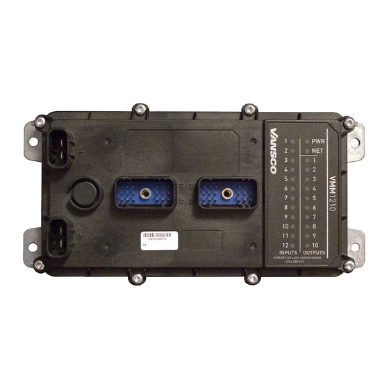
Page 52: Diagnostic Leds
Diagnostic LEDs 7. Diagnostic LEDs The VMM1210 has 24 red LEDs that are used to indicate the status of inputs, outputs, power and the Controller Area Network (CAN). The following shows the VMM1210's LEDs as they appear on the product: Figure 20: VMM1210 diagnostic LEDs 7.1. -
Page 53: Output Leds
Diagnostic LEDs 7.2. Output LEDs Output LEDs are used to indicate the status of high-side outputs. Output LEDs are labeled “OUT” (1 to 10) on the VMM1210. 7.3. Power LED The power LED (labeled PWR) is used to indicate the status of power, software, and faults on the VMM1210. -
Page 54: Connectors
Connectors 8. Connectors The VMM1210 has 2 Delphi Metri-pack series 18-pin connectors, as follows: White (J1): Mating Connector, Delphi Metri-pack 15492547; Contacts, Delphi 12103881 Black (J2): Mating Connector, Delphi Metri-pack 15492546; Contacts, Delphi 12103881 The connectors have pins that connect to inputs, outputs, network ports, and logic power used by the VMM1210. -
Page 55: Pinouts
Connectors The following is an image of the required connector: Figure 23: Connector J3/J4 8.1. Pinouts Connector pins connect to inputs, outputs, and communication channels. They provide the interface between the vehicle harness and the internal circuitry of the VMM1210. The following tables show the pinouts for each connector: J1 (White) Connector Pinout Name... - Page 56 Connectors J2 (Black) Connector Pinout Name Function RS232_RX Not used, Pseudo port for factory use only INPUT8_D Digital input OUTPUT3_10A_HS 10A High-side output OUTPUT10_3A Analog or Digital input INPUT7_D Analog or Digital input GND_LOWSIDE Low-side output ground BOOTSTRAP Not used, Pseudo port for factory use only INPUT9_ADF Analog Digital or Frequency input INPUT11_ADF...
-
Page 57: Installation
Installation 9. Installation Because every system is different, it is not feasible to provide detailed installation instructions that will be suitable for every assembly. This chapter therefore provides only high-level guidelines on installing the VMM1210. The vehicle manufacturer is responsible for creating procedures for mounting the VMM1210 in a vehicle during production assembly. - Page 58 Installation Before mounting the VMM1210, review the following environmental and mechanical requirements. Note: Do not install the VMM1210 near any significant heat sources, such as a turbo, exhaust manifold, etc. Avoid installing the VMM1210 near any drive- train component, such as a transmission or engine block. 9.1.2.1.
-
Page 59: Mounting The Vmm1210 To A Vehicle
Installation 9.1.3. Mounting the VMM1210 to a Vehicle It is up to the original equipment manufacturer (OEM) to ensure the product is securely mounted to the vehicle. The following guidelines are related to physically attaching the VMM1210 to a vehicle: ... - Page 60 Installation The vehicle harness design depends on the following: How the VMM1210's inputs, outputs, communication, and power pins are configured. Other components on the vehicle and their physical locations. The routing of the harness. Suggested wire sizing for the various connections are as follows: ...
-
Page 61: Application Examples
Application Examples 10. Application Examples The purpose of this section is to provide examples of how the VMM1210 can be used for different purposes. The following examples (used for illustrative purposes only) are covered in this section: Implementing safety interlocks ... -
Page 62: Controlling Indicator Lights
Application Examples The following diagram shows a typical seat switch interlock connection: Internal to product Battery Voltage Driver Present Switch Digital Input Figure 26: Seat switch interlock connection 10.2. Controlling Indicator Lights Multiple VMM1210 can be used together in a system to control a vehicle's indicator lights. -
Page 63: Controlling Motor Speed
Application Examples The following shows how to connect three VMM1210s together in a system to control indicator lights: Rear Rear Right Signal Light Rear Left Signal Light Cabin VBAT VBAT 3.3k 3.3k Right Turn Signal Switch Left Turn Signal Switch VBAT 3.3k Hazard Signal Switch... - Page 64 Application Examples software. Refer to the appropriate software manual, or contact your Parker Vansco Account Representative for more details about software. This section only provides hardware connection information. To do this, you would use a high-side output with PWM capabilities to control the speed of the motor, and a DC-coupled frequency input to monitor the output from the motor.
-
Page 65: Using One Analog Input As Two Digital Inputs
You will need to write your application logic to act according to the voltage value readings provided by the analog input. Refer to the appropriate help file, or contact your Parker Vansco Account Representative for more information. When making the connection, ensure there is a voltage difference between the two pins on the SPDT switch. -
Page 66: Connecting Various Sensors
Application Examples 10.5. Connecting Various Sensors There are many types of sensors that can be connected to the VMM1210, as follows: Open collector sensors Variable resistance sensors Variable reluctance sensors Switch sensors Voltage sensors CMOS sensors ... - Page 67 Application Examples The following shows a typical NPN open collector sensor connection: Internal to product Digital or frequency Input Open collector Figure 30: Open collector sensor connection The following shows a typical PNP open collector (also called open emitter) sensor connection: Internal to product Open collector...
-
Page 68: Variable Resistance
Application Examples 10.5.2. Variable Resistance Variable resistance sensors change impedance to represent it's measured value, and are compatible with analog inputs. Variable resistance sensors are typically used in thermal and pressure applications. They work by changing the voltage reading on the sensor according to changes in pressure or temperature in the application. -
Page 69: Variable Reluctance
Application Examples 10.5.3. Variable Reluctance Variable reluctance sensors are typically used in frequency measurement applications, and are compatible with AC-coupled frequency inputs. Variable reluctance sensors do not require power (the power is induced), and they create frequency by out-putting a sine wave type signal. They work by using an increase or decrease in a magnetic field to detect the proximity of a part or device. -
Page 70: Voltage
Application Examples The following shows a typical sensor switch connection: Internal to product Battery voltage Switch Digital Input Figure 34: Switch sensor connection 10.5.5. Voltage Voltage type sensors work by driving an analog voltage signal to report the sensor's measured value. Voltage sensors are compatible with analog inputs, and are typically used in applications that require variable voltage measurements. -
Page 71: Cmos
Application Examples The following shows a typical voltage sensor connection: Internal to product Voltage Sensor Analog Input Figure 35: Voltage sensor connection 10.5.6. CMOS A sensor with a CMOS-type output drives a high and low signal, and is typically used in digital and frequency applications, and therefore, CMOS sensors can be wired directly to digital and frequency inputs. -
Page 72: Potentiometer (Ratiometric)
Application Examples 10.5.7. Potentiometer (Ratiometric) Potentiometers and other ratiometric type sensors can be wired directly to analog inputs. Potentiometers are resistive devices that use a wiper arm to create a voltage divider. Changes to resistive measurements happen as the wiper arm moves along a resistive element. -
Page 73: Startup
Startup 11. Startup Danger! Risk of injury. If the control system is not fitted properly, the machine could move uncontrollably. Do not start the machine's engine before the control system is completely fitted and its signals are verified. In addition to the measures described below, the machine must also meet the machine directives of the country in question. - Page 74 Startup Prepare for system start Danger! Risk of injury. Make sure no one is in dangerous proximity to the vehicle. Prepare for the initial system start as follows: 1. Ensure that the engine for the hydraulic system's pump is in the off position. 2.
-
Page 75: Test
Test 12. Test The following table lists the verification tests that were performed for the VMM1210: Test Specifications Ref # Test Specification Test Description Deviation? J1455 (Jun 2006) 24 Hour Thermal Cycle Section 4.1.3.1 J1455 (Jun 2006) Thermal Shock Section 4.1.3.2 EP455 (Feb 03) Storage Temperature (non- Section 5.1.2... - Page 76 Test Test Specifications Ref # Test Specification Test Description Deviation? J1455 (Jun 2006) Operating Voltage Section 4.13.1.1 and Section 4.13.1.2 EP455 (Feb 03) Starting Voltage Section 5.10.6 EP455 (Feb 03) Operational Power Up Section 5.10.7 J1455 (Jun 2006) Jumper Starts Voltage Section 4.13.1 EP455 (Feb 03) Steady State Reverse Polarity...
-
Page 77: Index
13. Index 10 A High-Side Outputs • 23 Gather Required Materials • 5 General safety regulations • vii 3 A High-Side/Low-Side Outputs • 26 High-Side Output Capabilities • 23 High-Side Output Configuration • 24 About the VMM1210 • 1 High-Side Output Diagnostics and Fault Detection • 32 Active-Low Digital Input Connections •... - Page 78 Index Over Current Fault Protection • 32 Overview • 5 Pinouts • 45 Potentiometer (Ratiometric) • 62 Power • 35 Power Control Digital Inputs • 13 Power Control Inputs Configuration • 13 Power LED • 43 Power Up the Development System • 8 Programmable Digital Input Capabilities •...
- Page 80 Vansco Multiplexing Module VMM1210 User Guide HY33-5001-IB/US...
Need help?
Do you have a question about the Vansco VMM1210 and is the answer not in the manual?
Questions and answers