Table of Contents
Advertisement
Bulletin HY11-5715-677/UK
Operation Manual
Series PWDXXA-40X
Design ³ 20
Electronic for
Proportional DC Valves
Parker Hannifin
Manufacturing Germany GmbH & Co. KG
Hydraulic Controls Division Europe
Gutenbergstr. 38
41564 Kaarst, Germany
Tel.: (+49) 181 99 44 43 0
E-mail: valveshcd@parker.com
Copyright © 2016, Parker Hannifin Corp.
Advertisement
Table of Contents

Related Manuals for Parker PWD Series


Summary of Contents for Parker PWD Series
- Page 1 Design ³ 20 Electronic for Proportional DC Valves Parker Hannifin Manufacturing Germany GmbH & Co. KG Hydraulic Controls Division Europe Gutenbergstr. 38 41564 Kaarst, Germany Tel.: (+49) 181 99 44 43 0 E-mail: valveshcd@parker.com Copyright © 2016, Parker Hannifin Corp.
- Page 2 The user must analyze all aspects of the application, follow applicable industry standards, and follow the information concerning the product in the current product catalog and in any other materials provided from Parker or its subsidiaries or authorized distributors.
-
Page 3: Table Of Contents
Guideline for closed loop applications 5.5.1. Application: Closed loop systems for position 5.5.2. Application: Closed loop systems for pressure (via pressure control valves) 5.6. Error messages Maintenance Trouble-shooting Repair / Service PWDXXA-40X_20 5715-677 UK.indd 26.01.17 Parker Hannifin Corporation Hydraulics Group... -
Page 4: Introduction
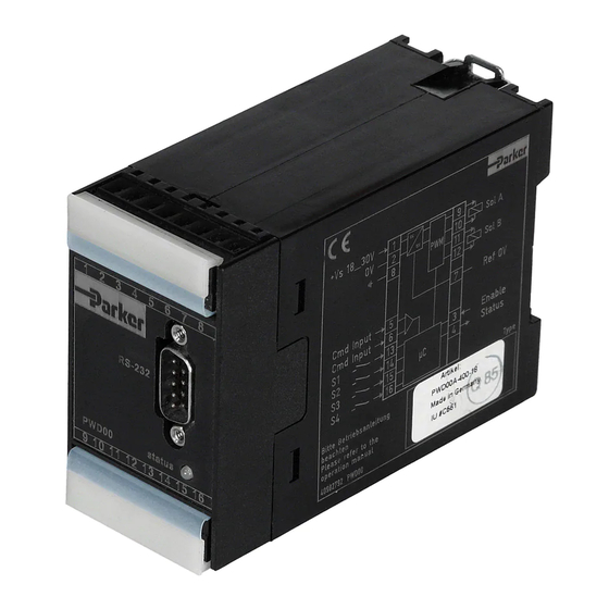
Front view / dimensions 1.2. Ordering code Electronic Position Amplifier, Technology Design module for control Min/Max adjustment, function series DC valves universal accel/decel ramps, command input Code Function Standard Linearization 1.3. Name plate PWDXXA-40X_20 5715-677 UK.indd 26.01.17 Parker Hannifin Corporation Hydraulics Group... -
Page 5: Block Diagram
Operation Manual Series PWDXXA-40X 1.4. Block diagram Parker electronic modules PWDXXA-40X for rail mounting are compact, easy to install and provide time-saving wiring by disconnectable terminals. The digital design of the circuit results in good accuracy and optimal adaption for proportional directional control valves with position sensor by a comfortable interface program. -
Page 6: Technical Data
16 overall braid shield for supply voltage and solenoids [AWG] 20 overall braid shield for sensor and signal Cable length [m] 50 Options Technology function Code1 Software adjustable transfer function with 10 compensation points for linearization of valve behaviour. PWDXXA-40X_20 5715-677 UK.indd 26.01.17 Parker Hannifin Corporation Hydraulics Group... -
Page 7: Signal Flow Diagram
Electronic for proportional DC valves Operation Manual Series PWDXXA-40X 1.7. Signal flow diagram PWDXXA-40X_20 5715-677 UK.indd 26.01.17 Parker Hannifin Corporation Hydraulics Group... -
Page 8: Safety Instructions
This operation manual is valid for module elec- tronics PWDXXA-40X series. Any use diverging or going beyond is deemed to be as not intended. The manufacturer is not liable for warranty claims resulting from this. PWDXXA-40X_20 5715-677 UK.indd 26.01.17 Parker Hannifin Corporation Hydraulics Group... -
Page 9: Mounting / Installation
An addi- tional folding unlocking lever allows simple removing of the terminal blocks and serves at once as shock hazard protection and mark- ing strip. PWDXXA-40X_20 5715-677 UK.indd 26.01.17 Parker Hannifin Corporation Hydraulics Group... -
Page 10: Electrical Interfacing
(cross section min. AWG 6 / 10 mm²). electronics resp. incorporated system parts. PWDXXA-40X_20 5715-677 UK.indd 26.01.17 Parker Hannifin Corporation Hydraulics Group... - Page 11 For the function description terminal 6 is assumed Incorrect signal amplitude levels may disturb as signal reference (0 V). the functionality and can damage the unit! PWDXXA-40X_20 5715-677 UK.indd 26.01.17 Parker Hannifin Corporation Hydraulics Group...
- Page 12 E19. NAMUR is an association of users of proc- off. The output will switched on when the input signal reaches a value of 3.8 mA, it switches ess control technology. PWDXXA-40X_20 5715-677 UK.indd 26.01.17 Parker Hannifin Corporation Hydraulics Group...
- Page 13 • feedback signal cable break (not for options voltage ±10 V / ±20 mA) • command signal cable break (only for option 4...20 mA) • internal processor fault • enable off Wiring diagram of status output PWDXXA-40X_20 5715-677 UK.indd 26.01.17 Parker Hannifin Corporation Hydraulics Group...
- Page 14 E11. The module is usable for valves of design series D*FS, RLL*R, WLL*R (standard con- nection). On appropriate selection of the parameter E11, sensors with other signal spans may be connected. PWDXXA-40X_20 5715-677 UK.indd 26.01.17 Parker Hannifin Corporation Hydraulics Group...
- Page 15 Electronic for proportional DC valves Operation Manual Series PWDXXA-40X Wiring diagram of standard sensor input (Parker valves) Wiring diagram of sensor input 0...±10 V Wiring diagram of sensor input 0...±20 mA / 4...12...20 mA, 3-wire Wiring diagram of sensor input 0...±20 mA / 4...12...20 mA, 2-wire PWDXXA-40X_20 5715-677 UK.indd 26.01.17...
- Page 16 Closed loop pressure control within a hydraulic R4V, R6V, RE*E*W, VMY). Command preset via cylinder, performed utilizing a proportional pres- external control signal. sure con trol valve with external electronic (RE06M, PWDXXA-40X_20 5715-677 UK.indd 26.01.17 Parker Hannifin Corporation Hydraulics Group...
- Page 17 Electronic for proportional DC valves Operation Manual Series PWDXXA-40X Example 2: Closed loop position control of a hydraulic cylinder, external electronics (D*FB). Command preset via utilizing a proportional directional control valve with external control signal. PWDXXA-40X_20 5715-677 UK.indd 26.01.17 Parker Hannifin Corporation Hydraulics Group...
- Page 18 Electronic for proportional DC valves Operation Manual Series PWDXXA-40X Example 3: Closed loop position control of a hydraulic cylinder, with external electronic (D*FS). Command preset performed via proportional directional control valve via external control signal. PWDXXA-40X_20 5715-677 UK.indd 26.01.17 Parker Hannifin Corporation Hydraulics Group...
-
Page 19: Operating Instructions
Storage of complete param- • Comfortable PC user software, free of charge: eter sets to floppy or hard disk is possible as well www.parker.com/euro_hcd - see "Support", or as printout or record as a text file for further docu- directly at www.parker.com/propxd. -
Page 20: Program Installation
• Terminate the execution of other programs. shows the ProPxD icon for starting the program. • Insert ProPxD-software CD. • Execute the file “setup.exe”. • Follow the instructions on the screen. PWDXXA-40X_20 5715-677 UK.indd 26.01.17 Parker Hannifin Corporation Hydraulics Group... -
Page 21: Software Operating
The name is • Select the engaged valve from the provided type “parker” and cannot be changed. Thus additionally table via the menu “Options” and the item “Valve to the button “Default” for loading of the default type”. -
Page 22: Adjustment Parameters
– 2 = ±20 mA 1 = ±10 V 3 = 4 ... 20 mA ±10 V: 0 cable break detection – ±20 mA: 0 command 4 ... 20 mA: 1 PWDXXA-40X_20 5715-677 UK.indd 26.01.17 Parker Hannifin Corporation Hydraulics Group... - Page 23 Adjustment of the operating mode for the command cable break detection. cable break detection To turn on resp. off the cable break detection for the command signal at a command selected command signal option of 4...20 mA. PWDXXA-40X_20 5715-677 UK.indd 26.01.17 Parker Hannifin Corporation Hydraulics Group...
- Page 24 4 = 1.3 A 0 = off (fast) Compability mode – 0 = off 1 = on (Design <20) Function 0 = Sensor supply – "Sensor supply" pin 1 = Comparator out PWDXXA-40X_20 5715-677 UK.indd 26.01.17 Parker Hannifin Corporation Hydraulics Group...
- Page 25 Adjustment of the control cycle. Compability mode To adapt the cycle time to design version <20. Adjustment of the "Sensor supply" pin. Funktion To select the function sensor supply or comparator out. "Sensor supply" pin PWDXXA-40X_20 5715-677 UK.indd 26.01.17 Parker Hannifin Corporation Hydraulics Group...
-
Page 26: Guideline For Closed Loop Applications
D), each with a user adjustable co- oscillations of the drive position. efficient. The user software provides therefore the parameters P16 (P), P17 (I) and P18 (D). PWDXXA-40X_20 5715-677 UK.indd 26.01.17 Parker Hannifin Corporation Hydraulics Group... - Page 27 This should be followed by returning of the drive to the start position, where the dwell in position may also be evaluated. PWDXXA-40X_20 5715-677 UK.indd 26.01.17 Parker Hannifin Corporation Hydraulics Group...
- Page 28 This parameter is only active if a window (> 0) is the slow oscillations. defined via P26. PWDXXA-40X_20 5715-677 UK.indd 26.01.17 Parker Hannifin Corporation Hydraulics Group...
- Page 29 Please obtain detailed information from the transducer supplier. PWDXXA-40X_20 5715-677 UK.indd 26.01.17 Parker Hannifin Corporation Hydraulics Group...
-
Page 30: Application: Closed Loop Systems For Pressure (Via Pressure Control Valves)
A too low a value of P17 causes low frequency oscillations, with a too higher value the required pressure may be reached too slowly. PWDXXA-40X_20 5715-677 UK.indd 26.01.17 Parker Hannifin Corporation Hydraulics Group... - Page 31 This should be followed by returning of the pres- sue to the start value, where the stationary value may also be evaluated. PWDXXA-40X_20 5715-677 UK.indd 26.01.17 Parker Hannifin Corporation Hydraulics Group...
- Page 32 In this case the integrator operates only within this window. Select this option via parameter P26. Step increases of the window size will eliminate the oscillation. PWDXXA-40X_20 5715-677 UK.indd 26.01.17 Parker Hannifin Corporation Hydraulics Group...
- Page 33 1000 Hz. This rate is fast enough to have negligible effect in almost all hydraulic applications, but it does set an absolute limit on the response of the system. PWDXXA-40X_20 5715-677 UK.indd 26.01.17 Parker Hannifin Corporation Hydraulics Group...
-
Page 34: Error Messages
The file name already exists within the indicated directory. Select Do you want to replace the file? another name, another directory or overwrite the existing file with “OK”. PWDXXA-40X_20 5715-677 UK.indd 26.01.17 Parker Hannifin Corporation Hydraulics Group... -
Page 35: Maintenance
(not for options voltage / +-20 mA) cable break command signal (only for option 4...20 mA) internal processor fault PWDXXA-40X_20 5715-677 UK.indd 26.01.17 Parker Hannifin Corporation Hydraulics Group... - Page 36 Electronic for proportional DC valves Operation Manual Series PWDXXA-40X Afterwards starting of trouble-shooting by means of a priority list of the most likely reasons. PWDXXA-40X_20 5715-677 UK.indd 26.01.17 Parker Hannifin Corporation Hydraulics Group...
-
Page 37: Repair / Service
• general support for starting up Parker hydraulic controls • maintenance of Parker controls • repair of all Parker related hydraulic and electrical devices • assistance in the supply of spare parts worldwide • direct service for mobile applications at our Service Center in Kaarst, Germany •...
Need help?
Do you have a question about the PWD Series and is the answer not in the manual?
Questions and answers