Table of Contents
Advertisement
PIO
We reserve the right to make technical changes
The data contained in this manual correspond to the current status at the time of printing.
Electromechanical Automation
Parker I/O-System
PROFIBUS DP ECO + I/O-Modules
Manual
Technical description,
installation and configuration
27.04.04 16:00
PIO-343 Profibus ECO 192-120855 N2 May 2004
Advertisement
Chapters
Table of Contents

Subscribe to Our Youtube Channel
Related Manuals for Parker PIO-400


Summary of Contents for Parker PIO-400
- Page 1 Electromechanical Automation Parker I/O-System PROFIBUS DP ECO + I/O-Modules Manual Technical description, installation and configuration We reserve the right to make technical changes 27.04.04 16:00 PIO-343 Profibus ECO 192-120855 N2 May 2004 The data contained in this manual correspond to the current status at the time of printing.
- Page 2 PIO P O-System arker Important comments Copyright © 2003 Parker Hannifin GmbH EME All rights reserved. Microsoft Word, Microsoft Office, Windows®, Window 95™, Window 98™, Windows NT®, Window 2000™, Window XP™ and MS-DOS™ are trademarks of Microsoft Corporation. EME - Electromechanical Automation Europe...
-
Page 3: Table Of Contents
3.12 Technical Data....................63 I/O Modules......................64 PIO-400 [2 DI DC 24 V 3.0 ms, high-side switching] ........64 PIO-402 [4 DI DC 24 V 3.0 ms, high-side switching] ........67 PIO-430 [8 DI DC 24 V 3.0 ms, high-side switching] ........70 PIO-456 [2 AI DC ± 10 V, Differential Inputs] ..........73 PIO-468 [4 AI DC 0-10 V, Single-Ended] ............77... - Page 4 PIO P O-System arker Important comments Glossary ......................121 Literature list ..................... 122 Index ........................123 PIO-343 Profibus ECO 192-120855 N2 May 2004...
-
Page 5: Important Comments
Important comments 1 Important comments To ensure fast installation and start-up of the units described in this manual, we strongly recommend that the following information and explanation is carefully read and adhered to. 1.1 Legal principles 1.1.1 Copyright This manual is copyrighted, together with all figures and illustrations contained therein. -
Page 6: Symbols
PIO P O-System arker Important comments 1.2 Symbols Danger Always abide by this information to protect persons from injury. Warning Always abide by this information to prevent damage to the device. Attention Marginal conditions must always be observed to ensure smooth operation. ESD (Electrostatic Discharge) Warning of damage to the components by electrostatic discharge. -
Page 7: Safety Notes
Important comments 1.5 Safety Notes Attention Switch off the I/O-System prior to working on bus modules! In the event of deformed contacts, the module in question is to be replaced, as its functionality can no longer be ensured on a long-term basis. The components are not resistant against materials having seeping and insulating properties. -
Page 8: O-System
DE DE AE AE DA DA DA DA DA DA DA DA AA AA AE AE AA AA DA DA AE AE A11 A12 A13 A14 PIO-400 PIO-400 PIO-602 PIO-XXX PIO-602 PIO-501 PIO-501 PIO-501 PIO-501 PIO-602 PIO-XXX PIO-XXX PIO-XXX PIO-XXX... -
Page 9: Technical Data
I/O-SYSTEM 2.2 Technical Data Mechanic Material Polycarbonate, Polyamide 6.6 Dimensions Coupler 50 mm x 65* mm x 97 mm Dimensions I/O module, single 12 mm x 64* mm x 100 mm Dimensions I/O module, double 24 mm x 64* mm x 100 mm Installation on DIN 35 with interlock modular by... - Page 10 PIO P O-System arker I/O-SYSTEM Safe electrical isolation Air and creepage distance acc. to IEC 60664-1 Degree of protection Degree of protection IP 20 Electromagnetic compatibility* Directive Test values Strength Evaluation class criteria Immunity to interference acc. to EN 50082-2 (96) EN 61000-4-2 4kV/8kV (2/4)
- Page 11 I/O-SYSTEM Maximum power dissipation of the components Bus modules 0,8 W / bus terminal (total power dissipation, system/field) ECO Fieldbus coupler 2,0 W / coupler Warning The power dissipation of all installed components must not exceed the maximum conductible power of the housing (cabinet). When dimensioning the housing, care is to be taken that even under high external temperatures, the temperature inside the housing does not exceed the permissible ambient temperature of 55 °C.
- Page 12 PIO P O-System arker I/O-SYSTEM Dimensions Dimensions in mm Side view Fig. 2-2: Dimensions PIO-343 Profibus ECO 192-120855 N2 May 2004...
-
Page 13: Manufacturing Number
I/O-SYSTEM 2.3 Manufacturing Number The manufacturing number is part of the lateral marking on the component. Manufacturing Number Calendar Year Software Hardware week version version Fig. 2-3: Manufacturing Number The manufacturing number consists of the production week and year, the software version (if available), the hardware version of the component, the firmware loader (if available) and further internal information for the manufacturer. -
Page 14: Mechanical Setup
PIO P O-System arker I/O-SYSTEM 2.5 Mechanical Setup 2.5.1 Installation Position Along with horizontal and vertical installation, all other installation positions are allowed. Attention In the case of vertical assembly, an end stop has to be mounted as an additional safeguard against slipping. - Page 15 I/O-SYSTEM 2.5.4 Spacing The spacing between adjacent components, cable conduits, casing and frame sides must be maintained for the complete field bus node. Fig. 2-4: Spacing The spacing creates room for heat transfer, installation or wiring. The spacing to cable conduits also prevents conducted electromagnetic interferences from influencing the operation.
- Page 16 PIO P O-System arker I/O-SYSTEM It is also possible to release an individual I/O module from the unit by pulling an unlocking lug. Fig. 2-6: removing bus terminal Danger Ensure that an interruption of the PE will not result in a condition which could endanger a person or equipment! For planning the ring feeding of the ground wire, please see chapter "Grounding Protection“...
- Page 17 I/O-SYSTEM 2.5.7 Internal Bus / Data Contacts Communication between the ECO coupler and the bus modules as well as the I/O- System supply of the bus modules is carried out via the internal bus. It is comprised of 6 data contacts, which are available as self-cleaning gold spring contacts. Fig.
- Page 18 PIO P O-System arker I/O-SYSTEM 2.5.8 Power Contacts Self-cleaning power contacts , are situated on the side of the components which further conduct the supply voltage for the field side. These contacts come as touchproof spring contacts on the right side of the coupler and the bus module. As fitting counterparts the module has male contacts on the left side.
- Page 19 I/O-SYSTEM 2.5.9 Wire Connection ® All components have CAGE CLAMP connections. ® The CAGE CLAMP connection is appropriate for solid, stranded and fine–stranded conductors. Each clamping unit accommodates one conductor. ® Fig. 2-9: CAGE CLAMP Connection The operating tool is inserted into the opening above the connection. This opens the ®...
-
Page 20: Power Supply
PIO P O-System arker I/O-SYSTEM 2.6 Power Supply 2.6.1 Isolation Within the fieldbus node, there are three electrically isolated potentials. • Operational voltage for the fieldbus interface. • Electronics of the couplers and the bus modules (internal bus). • All bus modules have an electrical isolation between the electronics (internal bus, logic) and the field electronics. - Page 21 I/O-SYSTEM 2.6.2 System Supply Connection The I/O-SYSTEM requires a 24 V direct current system supply (-15% or +20 %). The power supply is provided via the coupler. The voltage supply is reverse voltage protected. system-supply Fig. 2-11: System Supply The direct current supplies all internal I/O-System components, e.g. ECO coupler electronics, fieldbus interface and bus modules via the internal bus (5 V system voltage).
- Page 22 PIO P O-System arker I/O-SYSTEM Internal current consumption Current consumption via system voltage: 5 V for electronics of the bus modules and ECO coupler Residual current for bus Available current for the bus modules. See terminals technical data ECO coupler. Example ECO coupler: internal current consumption : 350 mA at 5V...
- Page 23 I/O-SYSTEM 2.6.3 Field Supply Connection Sensors and actuators can be directly connected to the relevant channel of the bus module in 1-/4 conductor connection technology. The bus module supplies power to the sensors and actuators. The input and output drivers of some bus modules require the field side supply voltage.
-
Page 24: Grounding
PIO P O-System arker I/O-SYSTEM 2.6.4 Power Supply Unit The I/O-SYSTEM requires a 24 V direct current system supply with a maximum deviation of -15% or +20 %. Recommendation A stable network supply cannot be taken for granted always and everywhere. Therefore, regulated power supply units should be used in order to guarantee the quality of the supply voltage. - Page 25 I/O-SYSTEM 2.7.2 Grounding Function The grounding function increases the resistance against disturbances from electro- magnetic interferences. Some components in the I/O system have a carrier rail contact that dissipates electro-magnetic disturbances to the carrier rail. Fig. 2-13: Carrier rail contact Attention Care must be taken to ensure the direct electrical connection between the carrier rail contact and the carrier rail.
- Page 26 PIO P O-System arker I/O-SYSTEM 2.7.3 Grounding Protection For the field side, the ground wire is connected to the lowest connection terminals of the power supply module. The ground connection is then connected to the next module via the Power Jumper Contact (PJC). If the bus module has the lower power jumper contact, then the ground wire connection of the field devices can be directly connected to the lower connection terminals of the bus module.
-
Page 27: Shielding (Screening)
I/O-SYSTEM 2.8 Shielding (Screening) 2.8.1 General The shielding of the data and signal conductors reduces electromagnetic interference thereby increasing the signal quality. Measurement errors, data transmission errors and even disturbances caused by overvoltage can be avoided. Attention Constant shielding is absolutely required in order to ensure the technical specifications in terms of the measurement accuracy. -
Page 28: Fieldbus Coupler
PIO P O-System arker Fieldbus Coupler 3 Fieldbus Coupler This chapter includes: 3.1 Description......................29 3.2 Hardware ......................30 3.2.1 View ....................... 30 3.2.2 Device Supply....................31 3.2.3 Fieldbus Connection..................31 3.2.4 Display Elements................... 32 3.2.5 Node Address....................32 3.2.6 Configuration Interface .................. -
Page 29: Description
Fieldbus Coupler 3.1 Description The Fieldbus Coupler maps the peripheral data of all I/O modules in the I/O-SYSTEM on PROFIBUS DP. In the initialization phase, the Fieldbus Coupler determines the physical structure of the node and creates a process image with all inputs and outputs. I/O modules with a bit width smaller than 8 can be combined to form one byte in order to optimize the address space. -
Page 30: Hardware
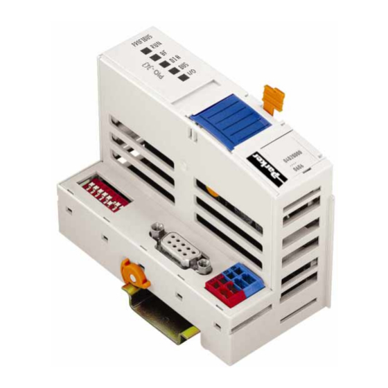
PIO P O-System arker Fieldbus Coupler 3.2 Hardware 3.2.1 View Status indication PROFIBUS -Fieldbus -Fieldbus node DIP switch Address Data contacts 01 02 03 04 Marking area Fieldbus connection D-Sub Supply Configuration interface Fig. 3-1: Fieldbus ECO-Coupler PROFIBUS DP The Fieldbus Coupler comprises of: •... -
Page 31: Device Supply
Fieldbus Coupler 3.2.2 Device Supply The supply is made via terminal bocks with CAGE CLAMP® connection. The device supply is intended both for the I/O-System and the field units. I/O Modules 1 / 2 24 V 24 V 10 nF 3 / 4 Fieldbus Interface... -
Page 32: Display Elements
PIO P O-System arker Fieldbus Coupler 3.2.4 Display Elements The operating condition of the Fieldbus Coupler or node is signaled via light diodes (LED). Fig. 3-4: Display elements PIO-343 Color Meaning The RUN-LED indicates to the operator if the Fieldbus green Coupler is correctly initialized. -
Page 33: Operating System
Fieldbus Coupler If an invalid address is set, the coupler adopts the address that has been assigned via Set_Slave_Address. This address is stored in the power fail safe EEPROM. The default address is 126. The node address is saved in the Fieldbus Coupler after switching on the device (initialization phase). -
Page 34: Process Image
PIO P O-System arker Fieldbus Coupler 3.4 Process Image 3.4.1 Local Process Image After switching on, the Coupler recognizes all I/O modules plugged into the node which supply or wait for data (data width/bit width > 0). Both analog and digital I/O modules can be used in the same node. -
Page 35: Process Images Of The I/O-Modules With Profibus-Dp
Motorola or in the Intel format. Note For the number of input and output bits or bytes of the individual I/O modules please refer to the corresponding I/O module description. 2 DI I/O-Modules PIO-400 Process Image [bit] Input Output PROFIBUS-DP... - Page 36 PIO P O-System arker Fieldbus Coupler 8 DO I/O-Modules PIO-530 Process Image [bit] Input Output PROFIBUS-DP 2 AI I/O-Modules PIO-480, PIO-456 Process Image [byte] Input Output PROFIBUS-DP PROFIBUS-DP Mapping MOTOROLA INTEL Input Output Input Output Channel 1 Channel 2 4 AI I/O-Modules PIO-468 Process Image [byte] Input...
-
Page 37: Configuration
There are one or two entries in the hardware cataloge for each I/O module. The module appear as PIO-xyz ... , for example PIO-400 2 DI/24 V DC/3.0 ms . For all binary modules an additional entry is made, *PIO-xyz ..When using this notation the Coupler adds the binary information to the current module in a byte which was previously opened with PIO-xyz ... -
Page 38: Identification Bytes
Modules are compiled in the table to make things simpler. Module Description Example Module Configuration of I/O modules PIO-400 2 DI/24 V DC/3.0 ms *-Module Configuration of digital I/O *PIO-400 2 DI/24 V DC/3.0 ms modules. Binary data is mapped to a byte that has already been started by “Module”. -
Page 39: Example
Fieldbus Coupler 3.5.3 Example The allocation of a fieldbus node with a Coupler and 17 I/O modules is shown below. DI DI DI DI DI DI AI AI DO DO AO AO AI AI DO DO DO DO DO DO AO AO AI AI DO DO... - Page 40 PIO P O-System arker Fieldbus Coupler I/O modules Module PI Master * Identification Inputs Outputs Digital output *PIO-504 4 DO/24 V DC/0.5 A AB9.4 Digital output 0x00 AB9.5 Digital output AB9.6 Digital output AB9.7 Potential supply Potential supply Analog output PIO-550 2 AO/0-10 V Analog output 0x61...
-
Page 41: Configuring The Coupler
Fieldbus Coupler 3.6 Configuring the Coupler Before a data exchange is possible between the master and slaves, configuring the coupler is necessary. The extended parameters (extended User_Prm_Data) is available as a selectable text in the configuration programs using the GSD files. Description Value Meaning... - Page 42 PIO P O-System arker Fieldbus Coupler The complete parameter record encompasses 34 configuration bytes. The first 10 bytes are laid down by the DP and DPV1 standard. The others contain manufacturer specific parameters. Byte No. Bit No. Value Meaning Standard Parameters Stations status (see EN 50170) 2-255 Watchdog factor 1...
-
Page 43: Configuring The Process Data Channel
Fieldbus Coupler 3.7 Configuring the Process Data Channel The process data channel serves for the communication between the Coupler and the higher ranking systems (Master or project and diagnostics PC). This channel is allocated to the Coupler and can not be used. When designing the node, this position should therefore always show “PIO-343 No process data channel”. -
Page 44: Configuration Of I/O Modules
Note For simplification, the tables only show the article number for the module designation. The module „PIO-400“ thus corresponds to the module „PIO-400 2 DI/24 V DC/3.0 ms“ 2 DI I/O Modules... - Page 45 Fieldbus Coupler 4 DI I/O Modules Module Identification Identification PIO-402 0x10 *PIO-402 0x00 Process Image Input Image Output Image in [bit] in [bit] Internal bus PROFIBUS DP Parameter Value Meaning I/O module is physically The I/O module process data is: plug fitted - supplied by the I/O module not plug fitted...
- Page 46 PIO P O-System arker Fieldbus Coupler Parameter Information Offset Plug 0 Plug Module is physically not present Module is physically present (default) Italic Cannot be changed 2 DO I/O Modules Module Identification Identification PIO-501 0x20 *PIO-501 0x00 Process Image Input Image Output Image in [bit] in [bit]...
- Page 47 Fieldbus Coupler 4 DO I/O Modules Module Identification Identification PIO-504 0x20 *PIO-504 0x00 Process Image Input Image Output Image in [bit] in [bit] Internal bus PROFIBUS DP Parameter Value Meaning I/O module is physically The I/O module process data is: plug fitted - supplied by the I/O module not plug fitted...
- Page 48 PIO P O-System arker Fieldbus Coupler 8 DO I/O Modules Identification Identification Module PIO-530 0x20 Process Image Input Image Output Image in [bit] in [bit] Internal bus PROFIBUS DP Parameter Value Meaning I/O module is physically The I/O module process data is: plug fitted - supplied by the I/O module not plug fitted...
-
Page 49: Analog I/O Modules
Fieldbus Coupler 3.8.2 Analog I/O Modules All analog I/O modules have 2 bytes of extendable configuration information, which serves for identification on internal bus and the formation of a mapping table. Analog inputs are followed by 2 bytes reserved for future options. The diagnostics message can be suppressed or released for each individual channel by means of modules capable of diagnostics. - Page 50 PIO P O-System arker Fieldbus Coupler 4 AI I/O Module Module Identification Identification PIO-468 0x53 Process Image Input Image Output Image in [byte] in [byte] Internal bus PROFIBUS DP Parameter Value Meaning I/O module is physically The I/O module process data is: plug fitted - supplied by the I/O module not plug fitted...
- Page 51 Fieldbus Coupler 2 AO I/O Modules Module Identification Identification PIO-550, PIO-552, PIO-556 0x61 Process Image Input Image Output Image in [byte] in [byte] Internal bus PROFIBUS DP Parameter Value Meaning I/O module is physically The I/O module process data is: plug fitted*) - supplied by the I/O module not plug fitted...
-
Page 52: Diagnostics
PIO P O-System arker Fieldbus Coupler 3.9 Diagnostics The slave diagnostics of the Coupler now comprises of a 6 byte standard diagnostics, a 9 byte identification diagnostics, a 7 byte device status and an up to 42 byte channel based diagnostics. In the reply telegram of the diagnostics, selection the identification based diagnostics and the device status are transmitted together with the standard diagnostics. -
Page 53: Manufacturer's Identification
Fieldbus Coupler 3.9.3 Manufacturer‘s Identification The manufacturer’s identification is located in byte 4 and 5 and includes a 16 bit code, which serves for the identification of the device or the device class. 3.9.4 Identification Based Diagnostics The identification based diagnostics is comprised of a bit field, which contains one bit of information for each connected module. - Page 54 PIO P O-System arker Fieldbus Coupler Internal Status Messages and Arguments Status Status Description Message Argument 0x00 0x00 No fault 0x01 0x01 Overflow inline code buffer 0x01 0x02 Unknown data type 0x01 0x03 EEPROM checksum fault 0x01 0x04 Fault when writing into the serial EEPROM 0x01 0x05 Fault when reading from the serial EEPROM...
-
Page 55: Channel Based Diagnostics
Fieldbus Coupler 3.9.6 Channel Based Diagnostics The channel based diagnostics is intended for detailing the identification based diagnostics. A structure is added to the device status for each faulty slot comprised of a header byte, a byte, the channel type supplying the channel number and a third byte, which describes the fault type and the channel organization. - Page 56 PIO P O-System arker Fieldbus Coupler Fault Types of I/O Modules with Diagnostic Capability The fault types refer to standardized types. Fault Meaning type Not specified Short circuit Low voltage High voltage Overload Over temperature Line break Upper limit value exceeded Lower limit value exceeded Fault 10 ...
-
Page 57: Led Signaling
Fieldbus Coupler 3.10 LED Signaling The Coupler possesses several LED's for on site signaling of the Coupler operating status or the complete node Fig. 3-10: Display elements PIO-343 The upper four LEDs (RUN, BF, DIA, BUS) display the state of the PROFIBUS communication. -
Page 58: Fieldbus Status
PIO P O-System arker Fieldbus Coupler 3.10.2 Fieldbus Status The upper four LED's signal the operating conditions of the PROFIBUS communication. Color Meaning green The RUN-LED indicates the correct power supply of the Fieldbus Coupler. The BF-LED indicates that the communication functions via the PROFIBUS. -
Page 59: Fault Message Via Blink Code Of The Bus-Led
Fault Description Remedy Argument Fault code 1: Fault in Configuration Telegram Insufficient configuration data Get in contact with PARKER support. The GSD file is defective or the parameter data were entered improperly. Excessive configuration data Get in contact with PARKER support. -
Page 60: Node Status
PIO P O-System arker Fieldbus Coupler 3.10.4 Node Status The I/O-LED indicates the node operation and signals faults occurring. Meaning green Data cycle on the internal bus No data cycle on the internal bus Coupler hardware defective When starting: internal bus is initialized blinks During operation: general internal bus fault Fault message during internal bus reset and internal fault:... -
Page 61: Fault Message Via The Blink Code Of The I/O Led
Fieldbus Coupler 3.10.5 Fault Message via the Blink Code of the I/O LED Fault Fault Description Remedy Argument Fault code 1: Hardware and Configuration Fault Overflow of the internal buffer Replace the Coupler memory for the inline code Unknown data type Replace the Coupler EEPROM checksum fault Replace the Coupler... -
Page 62: Fault Behavior
PIO P O-System arker Fieldbus Coupler Fault Fault Description Remedy Argument Fault code 5: Register Communication Fault Internal bus fault during Switch off the supply voltage of register communication with the coupler. Replace the nth the I/O module n module and switch the supply voltage on again. -
Page 63: Technical Data
1 x D-SUB 9; female Standards and Approvals UL (UL508) E198563 Standard EN 50170 Conformity marking Accessories GSD files PIO-343.GSD (on CD from Parker) GSD (german) GSE (english) GSG (general) Technical Data Number of I/O modules Protocol Input process image max. 32 byte Output process image max. -
Page 64: O Modules
Powerjumpercontacts Fig. 4.1.1-1: 2-Channel Digital Input Module PIO-400 4.1.2 Description The digital input module PIO-400 receives control signals from digital field devices (sensors, switches, etc.). The module is a 2- to 4-conductor device and has two input channels. Two sensors may be directly connected to the module. - Page 65 Input DI 2: Signal voltage (0) Status Fig. 4.1.3-1: green DI 2 Input DI 2: Signal voltage (1) Display Elements 4.1.4 Schematic Diagram 270pF 10nF 10nF 10nF PIO-400 Fig. 4.1.4-1: 2-Channel Digital Input Module PIO-400 PIO-343 Profibus ECO 192-120855 N2 May 2004...
- Page 66 PIO P O-System arker I/O Modules 4.1.5 Technical Data Module Specific Data Number of inputs Current consumption (internal) 3.7 mA Nominal voltage DC 24 V (-15 % / +20%) Signal voltage (0) DC -3 V to +5 V Signal voltage (1) DC 15 V to 30 V Input filter 3.0 ms...
-
Page 67: Di Dc 24 V 3.0 Ms, High-Side Switching]
I/O modules or from a supply module . The supply voltage for the field side is made automatically through the individual I/O modules by means of power jumper contacts. The digital input module can be used with all couplers of the PARKER-I/O-SYSTEM PIO. - Page 68 PIO P O-System arker I/O Modules 4.2.3 Display Elements Channel Designation State Function Status Input DI 1: Signal voltage (0) green DI 1 Input DI 1: Signal voltage (1) Status Input DI 2: Signal voltage (0) green DI 2 Input DI 2: Signal voltage (1) Status Input DI 3: Signal voltage (0) green...
- Page 69 I/O Modules 4.2.5 Technical Data Module Specific Data Number of inputs Current consumption (internal) 7.5 mA Nominal voltage DC 24 V (-15 % / +20 %) Signal voltage (0) DC -3 V to +5 V Signal voltage (1) DC 15 V to 30 V Input filter 3.0 ms Current supply...
-
Page 70: Di Dc 24 V 3.0 Ms, High-Side Switching]
. The supply voltage for the field side is made automatically through the individual I/O modules by means of power jumper contacts. The digital input module can be used with all couplers of the PARKER-I/O-SYSTEM PIO. - Page 71 I/O Modules 4.3.3 Display Elements Channel Designation State Function Status Input DI 1: Signal voltage (0) green DI 1 Input DI 1: Signal voltage (1) Status Input DI 2: Signal voltage (0) green DI 2 Input DI 2: Signal voltage (1) Status Input DI 3: Signal voltage (0) green...
- Page 72 PIO P O-System arker I/O Modules 4.3.5 Technical Data Module Specific Data Number of inputs Current consumption (internal) 17 mA Signal voltage (0) DC -3 V to +5 V Signal voltage (1) DC 15 V to 30 V Input filter 3.0 ms Current supply 2.8 mA...
-
Page 73: Ai Dc ± 10 V, Differential Inputs]
This module has no power contacts. For field supply to downstream I/O modules, a supply module will be needed. The analog input module can be used with all couplers of the PARKER-I/O-SYSTEM PIO. PIO-343 Profibus ECO 192-120855 N2 May 2004... - Page 74 PIO P O-System arker I/O Modules 4.4.3 Display Elements Channel Meaning State Function No operational readiness or the internal data bus communication is interrupted Function green AI 1 Operational readiness and 13 14 trouble-free internal data bus communication No operational readiness or the Fig.
- Page 75 I/O Modules 4.4.5 Technical Data Module Specific Data Number of inputs Voltage supply via system voltage DC /DC Current consumption . (internal) 80 mA Common mode voltage 35 V max. Signal current ± 10 V Input resistance 570 k Ω Resolution 12 bits Conversion time...
- Page 76 PIO P O-System arker I/O Modules Attention The representation of the process data of some fieldbus modules in the process image depends on the fieldbus coupler used. Please take this information as well as the particular design of the respective control/status bytes from the description of the process image of the corresponding coupler.
-
Page 77: Ai Dc 0-10 V, Single-Ended]
This module has no power contacts. For field supply to downstream I/O modules, a supply module will be needed. The analog input module can be used with all couplers of the PARKER-I/O-SYSTEM PIO. PIO-343 Profibus ECO 192-120855 N2 May 2004... - Page 78 PIO P O-System arker I/O Modules 4.5.3 Display Elements Channel Designation State Function No operational readiness or the internal data bus communication is Function interrupted green AI 1 Operational readiness and trouble-free internal data bus communication No operational readiness or the internal data bus communication is Function...
- Page 79 I/O Modules 4.5.5 Technical Data Module Specific Data Number of inputs Voltage supply via system voltage DC /DC Current consumption . (internal) 60 mA Input voltage 35 V max. Signal voltage 0 V... 10 V 133 k Ω Internal resistance Resolution 12 Bit Conversion time...
-
Page 80: Ai 0-20 Ma Differential Measurement Input]
PIO P O-System arker I/O Modules Attention The representation of the process data of some fieldbus modules in the process image depends on the fieldbus coupler used. Please take this information as well as the particular design of the respective control/status bytes from the section "Fieldbus specific design of the process data"... - Page 81 The voltage supply is done via system voltage. Attention This module has no power contacts. For field supply to downstream I/O modules, a supply module will be needed. The analog input module can be used with all couplers of the PARKER-I/O-SYSTEM PIO. 4.6.3 Display Elements Channel...
- Page 82 PIO P O-System arker I/O Modules 4.6.4 Schematic Diagram +AI1 +AI2 -AI1 -AI2 Logic 270pF Error Function 270pF Shield Shield (screen) (screen) PIO-480 Fig. 4.6.4-1: 2-Channel Analog Input Module 0-20 mA PIO-343 Profibus ECO 192-120855 N2 May 2004...
- Page 83 I/O Modules 4.6.5 Technical Data Module Specific Data Number of outputs 2, electrically isolated from each other Measured-value acquisition time synchronous (both inputs) Voltage supply via system voltage DC /DC Current consumption (internal) ≤ 100 mA Signal current 0 ... 20 mA Internal resistance <...
- Page 84 PIO P O-System arker I/O Modules 4.6.6 Process Image The analog input module PIO-480 transmits 16-bit measured values and 8 optional status bits per channel. The digitalized measured value is transmitted in a data word (16 bits) as input byte 0 (low) and input byte 1 (high) into the process image of the coupler.
-
Page 85: Do Dc 24 V 0.5 A, High-Side Switching]
I/O modules or from a supply module . The supply voltage for the field side is made automatically through the individual I/O modules by means of power jumper contacts. The digital output module can be used with all couplers of the PARKER-I/O-SYSTEM PIO. - Page 86 PIO P O-System arker I/O Modules 4.7.3 Display Elements Channel Designation State Function Output DO 1: not active Status green DO 1 Output DO 1: active Output DO 2: not active Status Fig. 4.7.3-1: green DO 2 Output DO 2: active Display Elements 4.7.4 Schematic Diagram 10nF...
- Page 87 I/O Modules 4.7.5 Technical Data Module Specific Data Number of outputs Current consumption (internal) 3.5 mA max. Voltage via power jumper contacts DC 24 V (-15 % / +20%) Type of load resistive, inductive, lamps Switching rate 5 kHz max. Reverse voltage protection Output current 0.5 A...
-
Page 88: Do Dc 24 V 0.5 A, High-Side Switching]
I/O modules or from a supply module . The supply voltage for the field side is made automatically through the individual I/O modules by means of power jumper contacts. The digital output module can be used with all couplers of the PARKER-I/O-SYSTEM PIO. - Page 89 I/O Modules 4.8.3 Display Elements Channel Designation State Function Status Output DO 1: not active green DO 1 Output DO 1: active Status Output DO 2: not active green DO 2 Output DO 2: active Status Output DO 3: not active green DO 3 Output DO 3: active...
- Page 90 PIO P O-System arker I/O Modules 4.8.5 Technical Data Module Specific Data Number of outputs Current consumption (internal) 7 mA max. Voltage via power jumper contacts DC 24 V (-15 % / + 20 %) Type of load resistive, inductive, lamps Switching rate 1 kHz max.
-
Page 91: Do Dc 24 V 0.5 A, High-Side Switching]
I/O modules or from a supply module. The supply voltage for the field side is made automatically through the individual I/O modules by means of power jumper contacts. The digital output module can be used with all couplers of the PARKER-I/O-SYSTEM PIO. - Page 92 PIO P O-System arker I/O Modules 4.9.3 Display Elements Channel Designation State Function Status Output DO 1: not active green DO 1 Output DO 1: active Status Output DO 2: not active green DO 2 Output DO 2: active Status Output DO 3: not active green DO 3...
- Page 93 I/O Modules 4.9.5 Technical Data Module Specific Data Number of outputs Current consumption (internal) 25 mA Voltage via power jumper contacts DC 24 V (-15 % / +20%) Type of load resistive, inductive, lamps Switching rate 2 kHz max. Reverse voltage protection Output current 0.5 A short-circuit-protected Absorbable energy Wmax.
-
Page 94: Ao Dc 0-10 V]
This module is not provided with integrated power jumper contacts. For field supply to downstream I/O modules, a supply module will be needed. The analog output module can be used with all couplers of the PARKER-I/O- SYSTEM PIO. PIO-343 Profibus ECO 192-120855 N2 May 2004... - Page 95 I/O Modules 4.10.3 Display Elements Channel Designation State Function No operational readiness or the internal data bus communication is interrupted Function green AO 1 Operational readiness and Fig. 4.10.3-1: trouble-free operational Display Elements readiness No operational readiness or the internal data bus communication is interrupted Function green...
- Page 96 PIO P O-System arker I/O Modules 4.10.5 Technical Data Module Specific Data Number of outputs Voltage supply via system voltage DC/DC Current consumption . (internal) 65 mA Signal voltage 0 ... 10 V Load impedance > 5 k Ω Resolution 12 Bit Conversion time 2 ms...
-
Page 97: Ao 0-20 Ma]
I/O Modules 4.10.7 Standard Format For the standard module PIO-550, the numerical values ranging from 0x0000 to 0x7FFF are scaled on the output voltage ranging from 0 V to 10 V. Process values of module PIO-550 Output voltage numerical value status- byte binary... - Page 98 Note Use an appropriate supply module (e.g. PIO-602) if an electrically isolated voltage supply is required! The analog output module can be used with all couplers of the PARKER-I/O- SYSTEM PIO. 4.11.3 Display Elements...
- Page 99 I/O Modules 4.11.4 Schematic Diagram Logic Function 270pF 10nF 10nF 10nF Shield Shield (screen) (screen) PIO-552 Fig. 4.11.4-1: 2-Channel Analog Output Module PIO-552 4.11.5 Technical Data Module Specific Data Number of outputs Voltage supply via system voltage DC 24 V (-15% ... +20%) Current consumption .
- Page 100 PIO P O-System arker I/O Modules Approvals E198563, UL508 KEMA 01ATEX1024 X II 3 G EEx nA II T4 GL (Germanischer Lloyd) 40 197-01 HH Cat. A, B, C, D (EMC1) LR (Lloyd's Register) 02/20026 Env. 1, 2, 3, 4 DNV (Det Norske Veritas) A-8471 Cl.
-
Page 101: Ao Dc ±10 V]
This module has no power contacts. For field supply to downstream I/O modules, a supply module will be needed. The analog output module can be used with all couplers of the PARKER-I/O- SYSTEM PIO. PIO-343 Profibus ECO 192-120855 N2 May 2004... - Page 102 PIO P O-System arker I/O Modules 4.12.3 Display Elements Channel Designatio State Function No operational readiness or the internal data bus communication is interrupted Function green AO 1 Operational readiness and 13 14 trouble-free operational readiness No operational readiness or Fig.
- Page 103 I/O Modules 4.12.5 Technical Data Module Specific Data Number of outputs Current consumption . (internal) 65 mA Voltage supply via system voltage DC/DC ± 10 V Signal voltage > 5 k Ω Load impedance ± 10 mV Linearity Resolution 12 Bit Conversion time 2 ms Measuring error...
-
Page 104: End Module]
PIO P O-System arker I/O Modules The three least significant bits (B0 ... B2) are not parsed. Some fieldbus systems can process status information by means of a status byte. As the returned status byte of this output module is always zero, it will not be parsed. 4.12.7 Standard Format For the standard module PIO-556, the numerical values ranging from 0x8001 to... - Page 105 After the fieldbus node is assembled with the correct buscoupler and selected I/O modules , the end module PIO-600 is snapped onto the assembly. This module completes the internal data circuit and ensures correct data flow. The end module is a necessary component to all PARKER-I/O-SYSTEM PIO fieldbus nodes. 4.13.3...
-
Page 106: Dc Power Supply]
Any configuration of the output modules is possible when designing the fieldbus node. Grouping of module types is not necessary. The supply module can be used with all couplers of the PARKER-I/O-SYSTEM PIO. PIO-343 Profibus ECO 192-120855 N2 May 2004... - Page 107 I/O Modules 4.14.3 Display Elements Designation State Function No DC 24 V voltage supply via Status voltage power jumper contacts. supply –Power green DC 24 V voltage supply via jumper Fig. 4.14.3-1: power jumper contacts. contacts Display Elements 4.14.4 Schematic Diagram Status PIO-602 Fig.
- Page 108 PIO P O-System arker I/O Modules 4.14.5 Technical Data Module Specific Data Voltage via power jumper contacts DC 24 V Current via power jumper contacts 10 A Weight ca. 45 g Approvals E198563, UL508 KEMA 01ATEX1024 X II 3 G EEx nA II T4 GL (Germanischer Lloyd) 40 197-01 HH Cat.
-
Page 109: Profibus
PROFIBUS 5 PROFIBUS 5.1 Description PROFIBUS is an open fieldbus standard, laid down in the European Standard EN 50170, Vol. 2 (also IEC). PROFIBUS DP has been designed for a fast and efficient data exchange between a control (PLC / PC) and decentralized peripheral equipment, for example sensors and actuators, digital or analog input and output modules. -
Page 110: Wiring
PIO P O-System arker PROFIBUS 5.2 Wiring On the PROFIBUS with RS 485 transmission technology all devices are connected in a line structure. The bus line comprises of a twisted and screened pair of wires. The fieldbus line is specified in EN 50170 as a line type A and must provide certain line parameters. - Page 111 PROFIBUS Note When connecting the subscriber ensure that the data lines are not mixed up. The bus termination at the start and end of the bus line must be installed. The bus connection requires the supply voltage VP from the device. For this reason ensure that the slave unit installed on the bus termination, is always supplied with voltage.
-
Page 112: Use In Hazardous Environments
PIO P O-System arker Use in Hazardous Environments 6 Use in Hazardous Environments 6.1 Foreword Today’s development shows that many chemical and petrochemical companies have production plants, production, and process automation machines in operation which use gas-air, vapor-air and dust-air mixtures which can be explosive. For this reason, the electrical components used in such plants and I/O-systems must not pose a risk of explosion resulting in injury to persons or damage to property. - Page 113 Use in Hazardous Environments Explosive areas resulting from gases, fumes or mist: • Zone 0 areas are subject to an explosive atmosphere (> 1000 h /year) continuously or for extended periods. • Zone 1 areas can expect the occasional occurrence of an explosive atmosphere (>...
- Page 114 PIO P O-System arker Use in Hazardous Environments 6.3.3 Unit categories Moreover, the areas of use (zones) and the conditions of use (explosion groups) are subdivided into categories for the electrical operating means: Unit Explosion Area of use categories group Fire-damp protection Fire-damp protection Zone 0 Explosive environment by gas, fumes or mist...
- Page 115 Use in Hazardous Environments The following table represents the division and attributes of the materials to the temperature classes and material groups in percent: Temperature classes Total* 26.6 % 42.8 % 25.5 % 94.9 % 4.9 % 0.2 % Explosion group Total* 85.2% 13.8 %...
-
Page 116: Classifications Meeting The Nec 500
PIO P O-System arker Use in Hazardous Environments Type “n” ignition protection additionally requires electrical components to be marked with the following extended identification: • A – non spark generating (function modules without relay /without switches) • AC – spark generating, contacts protected by seals (function modules with relays / without switches) •... - Page 117 Use in Hazardous Environments 6.4.3 Temperature classes Electrical components for explosive areas are differentiated by temperature classes: Maximum Ignition temperature Temperature classes surface temperature of the combustible materials 450 °C > 450 °C 300 °C > 300 °C to 450 °C 280 °C >...
-
Page 118: Identification
E = conforming with European standards Ex = explosion protected component n = Type of ignition Extended identification Fig. 6-1: Example for lateral labeling of bus modules (PIO-400, 2 channel digital input module 24 V DC) PIO-343 Profibus ECO 192-120855 N2 May 2004... - Page 119 CL I DIV 2 Explosion group Grp. ABCD (gas group) optemp code T4A Temperature class Fig. 6-2: Example for lateral labeling of bus modules (PIO-400, 2 channel digital input module 24 V DC) PIO-343 Profibus ECO 192-120855 N2 May 2004...
-
Page 120: Installation Regulations
PIO P O-System arker Use in Hazardous Environments 6.6 Installation regulations In the Federal Republic of Germany, various national regulations for the installation in explosive areas must be taken into consideration. The basis being the ElexV complemented by the installation regulation DIN VDE 0165/2.91. The following are excerpts from additional VDE regulations: DIN VDE 0100 Installation in power plants with rated voltages up to 1000 V... - Page 121 Literature list 7 Glossary Smallest information unit. Its value can either be 1 or 0. Bit rate Number of bits transmitted within a time unit. Line for bit serial or bit parallel, clocked data transfer. A bus for the bit parallel data transmission comprises of address, data, control and supply bus.
- Page 122 PIO P O-System arker Literature list 8 Literature list Further information The PNO provides further documentation for its members in INTERNET. Cable specification information can be obtained from, for example, the „Installation Guideline for PROFIBUS-FMS/DP", 2.112 http://www.profibus.com/ PIO-343 Profibus ECO 192-120855 N2 May 2004...
- Page 123 Index 9 Index carrier rail ..............14, 16 PIO-400 [2 DI DC 24 V 3.0 ms, High-Side Switching]..64 contacts PIO-402 [4 DI DC 24 V 3.0 ms, High-Side Switching]..67 data-................17 PIO-430 [8 DI DC 24 V 3.0 ms, High-Side Switching]..70 power- ................
Need help?
Do you have a question about the PIO-400 and is the answer not in the manual?
Questions and answers