Table of Contents
Advertisement
Bulletin MSG11-5715-686/UK
Operation Manual
Series D*FC / D*1FC
D*FC Design ≥ 10
D*1FC Design ≥ 10
Proportional Directional
Control Valves
Parker Hannifin
Manufacturing Germany GmbH & Co. KG
Industrial Systems Division Europe
Gutenbergstr. 38
41564 Kaarst, Germany
Tel.: (+49) 181 99 44 43 0
E-mail: valvesisde@parker.com
Copyright © 2019, Parker Hannifin Corp.
Advertisement
Table of Contents

Related Manuals for Parker D 1FC Series


Summary of Contents for Parker D 1FC Series
- Page 1 D*1FC Design ≥ 10 Proportional Directional Control Valves Parker Hannifin Manufacturing Germany GmbH & Co. KG Industrial Systems Division Europe Gutenbergstr. 38 41564 Kaarst, Germany Tel.: (+49) 181 99 44 43 0 E-mail: valvesisde@parker.com Copyright © 2019, Parker Hannifin Corp.
- Page 2 The user must analyze all aspects of the application, follow applicable industry standards, and follow the information concerning the product in the current product catalog and in any other materials provided from Parker or its subsidiaries or authorized distributors.
-
Page 3: Table Of Contents
Storage Commissioning Pressure fluids Electrical connection Electrical interfacing ProPxD parametrizing software Operation Service/maintenance Air bleeding of hydraulic system Filter Flushing Decommissioning Disposal Trouble shooting Product information Other applicable standards/rules Accessories / spare parts D_FC 5715-686 UK 07.02.2019 Parker Hannifin Corporation... -
Page 4: Introduction
B – T with pressure drops above 120 bar or contamination in the hydraulic fluid. Approx. 10 % opening, only zero lapped spools and underlap spools. Only for overlapped spools. Needs to be removed at tank pressure >35 bar. Please order connector separately. D_FC 5715-686 UK 07.02.2019 Parker Hannifin Corporation... -
Page 5: Ordering Code D*1Fc
P -> A 12...20 mA 4...20 mA P -> A With enlarged connections Ø 32 mm. Not for D111FCZ*. Monitor switch for hybrid valves: code 8 includes options of code L (24 V normally closed). D_FC 5715-686 UK 07.02.2019 Parker Hannifin Corporation... -
Page 6: Name Plate Example
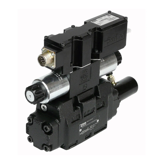
Parker D*FC and D*1FC proportional directional control valves have an integral electronics. Differ- ent flow sizes as well as command signal options are available to achieve an optimal adaption for different applications. -
Page 7: Block Diagram Of Integral Electronics
Block diagram of integral electronics D*FC, Code 0 (6+PE) D*1FC, Code 0 (6+PE) D*FC, Code 5 (11+PE) D*1FC, Code 5 (11+PE) D*FC, Code 7 (6+PE with enable) D*1FC, Code 7 (6+PE with enable) D_FC 5715-686 UK 07.02.2019 Parker Hannifin Corporation... -
Page 8: Technical Data
If valves with onboard electronics are used in safety-related parts of control systems, in case the safety function is requested, the valve electronics voltage supply is to be switched off by a suitable switching element with sufficient reliability. D_FC 5715-686 UK 07.02.2019 Parker Hannifin Corporation... -
Page 9: Signal Flow Diagram
Proportional DC Valves Operation Manual Series D*FC, D*1FC Signal flow diagram D_FC 5715-686 UK 07.02.2019 Parker Hannifin Corporation... -
Page 10: Scope Of Supply
• operation outside the specification Do not disassemble the valve! In case of suspicion for a defect please return it to Parker. D_FC 5715-686 UK 07.02.2019 Parker Hannifin Corporation... -
Page 11: Use Of The Product
Leaking plugs may constitute a safety hazard, so the This product is a safety component that may valve must be returned to Parker for repair. only be repaired by the manufacturer if it Lightning malfunctions. If the safety components are... -
Page 12: Use Of The Product
“Personnel requirements”, “Remaining risks”. The product is delivered with adequate corrosion Compare valve type (located on the name plate) protection, provided our recommendations for the with part list resp. circuit diagram. ambient conditions are followed. D_FC 5715-686 UK 07.02.2019 Parker Hannifin Corporation... -
Page 13: Pressure Fluids
50 m various pressure fluids: The above information serves for orientation and does not substitute user For cable lengths > 50 m consult Parker. tests among the particular operating conditions. Particularly no liability for media compatibility may The connection cable is coupled to the female be derived out of it. - Page 14 Cable length max. 50 m have to be tied to the protective earth termi- For cable lengths > 50 m consult Parker. nal within the control unit. It is necessary to use a low ohmic potential connection between The connection cable is coupled to the female control unit and machine frame to prevent connector by crimp contacts.
-
Page 15: Electrical Interfacing
Due to the inrush current of the valve the current limit circuit may respond prema- turely and create problems during energizing of the supply voltage. Wiring diagram of supply voltage Code 0/7 (6 + PE) Code 5 (11 + PE) D_FC 5715-686 UK 07.02.2019 Parker Hannifin Corporation... - Page 16 Wiring diagram of enable input Code 5 (11 + PE) Wiring diagram of enable input code 7 (6 + PE) D_FC 5715-686 UK 07.02.2019 Parker Hannifin Corporation...
- Page 17 The command input signal needs to be filtered control technology. as well as free of inductive surges and modulations. Due to the sensitivity of the valve a high signal quality is recommended, this will prevent malfunction. D_FC 5715-686 UK 07.02.2019 Parker Hannifin Corporation...
- Page 18 Wiring diagram of current command input 4...12...20 mA Code 0/7 (6 + PE) Wiring diagram of voltage command input +10...0...-10 V Code 5 (11 + PE) Wiring diagram of current command input 4...12...20 mA Code 5 (11 + PE) D_FC 5715-686 UK 07.02.2019 Parker Hannifin Corporation...
- Page 19 0...+100 % 0...+10 V signal 0...-100 % 0...-10 V Wiring diagram of diagnostics output Code 7 (6 + PE) Wiring diagram of diagnostics output Code 5 (11 + PE) D_FC 5715-686 UK 07.02.2019 Parker Hannifin Corporation...
-
Page 20: Propxd Parametrizing Software
Attention! The valve electronic provides no See www.parker.com/isde section “Support” or USB interface, but can only be parametrized directly at www.parker.com/propxd for free software via an RS232 - connection. Therefore the download. usage of USB standard cables is permitted and may result in damaging of valve resp. - Page 21 • Connect the valve electronic to a PC via the The expert mode is protected by a pass word parametrizing cable. request. The name is “parker”. The button “Send • Start the operating program. parameter” appears in the “Expert”-operating mode.
- Page 22 0 - 32500 ramp decel. AB B To avoid switching noise. Adjustment of the handling by detecting a fault. 0, 255, 768, – Errorhandling For the alignment of the valve reaction at fault diagnosis 1023 D_FC 5715-686 UK 07.02.2019 Parker Hannifin Corporation...
-
Page 23: Operation
"Other applicable standards/rules", “Personnel hydraulic fluid is required. The frequency of change requirements”, “Remaining risks”. depends from the following circumstances: • kind resp. grade of the pressure fluid • filtering • operating temperature and environmental conditions D_FC 5715-686 UK 07.02.2019 Parker Hannifin Corporation... -
Page 24: Trouble Shooting
• German Occupation Safety Ordinance (Be- – Part 1: General requirements triebssicherheitsverordnung) • DIN EN 60529; VDE 0470-1:2000-09 Degrees • German Labour Protection Act (Arbeitsschutz- of protection provided by enclosures (IP code) gesetz) D_FC 5715-686 UK 07.02.2019 Parker Hannifin Corporation... -
Page 25: Accessories / Spare Parts
Please direct technical product enquiries to: Parker Hannifin Manufacturing Germany GmbH & Co. KG Industrial Systems Division Europe Gutenbergstr. 38 41564 Kaarst, Germany Tel.: (+49) 181 99 44 43 0 E-mail: valvesisde@parker.com Hotline in Europe Phone: 00800-2727-5374 D_FC 5715-686 UK 07.02.2019 Parker Hannifin Corporation...
Need help?
Do you have a question about the D 1FC Series and is the answer not in the manual?
Questions and answers