Parker DxFB Series Operation Manual

Parker DxFB Series Operation Manual

With integrated electronics, proportional directional control valve

Advertisement

Bulletin MSG11-5715-669/UK
Operation Manual
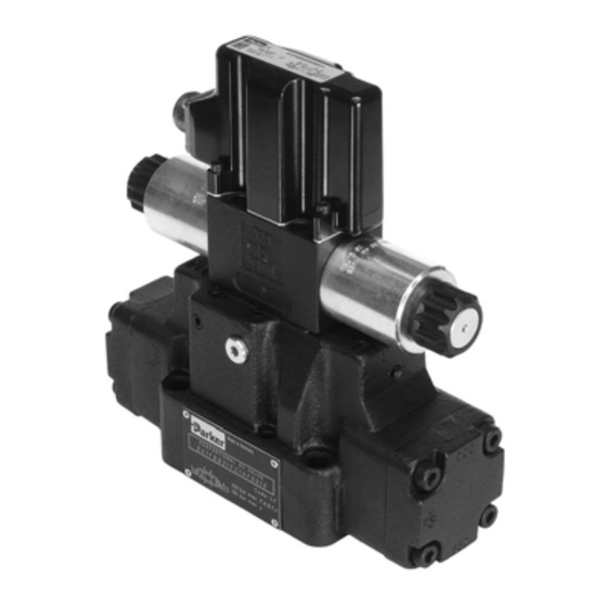
Series D*FB / D*1FB with
Integrated Electronics
D*FB Design ³ 12
D*1FB Design ³ 10
Proportional Directional
Control Valve
Parker Hannifin
Manufacturing Germany GmbH & Co. KG
Industrial Systems Division Europe
Gutenbergstr. 38
41564 Kaarst, Germany
Tel.: (+49) 181 99 44 43 0
E-mail: valvesisde@parker.com
Copyright © 2019, Parker Hannifin Corp.

Advertisement

Table of Contents
loading

Summary of Contents for Parker DxFB Series

  • Page 1 D*1FB Design ³ 10 Proportional Directional Control Valve Parker Hannifin Manufacturing Germany GmbH & Co. KG Industrial Systems Division Europe Gutenbergstr. 38 41564 Kaarst, Germany Tel.: (+49) 181 99 44 43 0 E-mail: valvesisde@parker.com Copyright © 2019, Parker Hannifin Corp.
  • Page 2 The user must analyze all aspects of the application, follow applicable industry standards, and follow the information concerning the product in the current product catalog and in any other materials provided from Parker or its subsidiaries or authorized distributors.
  • Page 3: Table Of Contents

    Storage Commissioning Pressure fluids Electrical connection Electrical interfacing ProPxD parametrizing software Operation Service/maintenance Air bleeding of hydraulic system Filter Flushing Decommissioning Disposal Trouble shooting Product information Other applicable standards/rules Accessories / spare parts D_FB-D_1FB_10-12 5715-669 UK.indd 25.06.19 Parker Hannifin Corporation...
  • Page 4: Introduction

    6 + PE – Pot.-supply & 0...+/-10 V 0...+10 V > P-A 11 + PE command preset 4...20 mA 12...20 mA > P-A channel Factory set +/-10 V Please order female connector separately. D_FB-D_1FB_10-12 5715-669 UK.indd 25.06.19 Parker Hannifin Corporation...
  • Page 5: Ordering Code D*1Fb

    & command 11 + PE 4...20 mA 12...20 mA > P-A preset channels Valve Code accessories Standard Monitor switch With enlarged connections Ø 32 mm As D1FV* separately available Please order female connector separately. D_FB-D_1FB_10-12 5715-669 UK.indd 25.06.19 Parker Hannifin Corporation...
  • Page 6: Name Plate Example

    Series D*FB / D*1FB Name Plate Example Block Diagram of Integral Electronics Code F0/M0 (6+PE) Parker D*FB/D*1FB proportional directional control Code S0/G0 (6+PE) valves have an integral electronic and requires only one sole electrical common for the control system. Different flow sizes, as well as command signal op- tions are available to achieve an optimal adaption for different applications.
  • Page 7: Technical Data

    Code W5: 11 + PE acc. EN 175201-804 Cable Specification [mm²] Codes F0, M0, S0, G0: 7 x 1.0 (AWG16) overall braid shield [mm²] Code W5: 11 x 1.0 (AWG16) overall braid shield Cable Length max. [m] 50 D_FB-D_1FB_10-12 5715-669 UK.indd 25.06.19 Parker Hannifin Corporation...
  • Page 8: Signal Flow Diagram

    Prop. Directional Control Valve Operation Manual Series D*FB / D*1FB Signal flow diagram D_FB-D_1FB_10-12 5715-669 UK.indd 25.06.19 Parker Hannifin Corporation...
  • Page 9: Scope Of Supply

    • operation outside the specification corporated system parts. Do not disassemble the valve! In case of sus- picion for a defect please return it to Parker. D_FB-D_1FB_10-12 5715-669 UK.indd 25.06.19 Parker Hannifin Corporation...
  • Page 10: Use Of The Product

    Leaking plugs may constitute a safety hazard, so the This product is a safety component that may valve must be returned to Parker for repair. only be repaired by the manufacturer if it mal- Lightning functions.
  • Page 11: Use Of The Product

    "Other applicable standards/ rules", “Personnel requirements”, “Remaining risks”. protection, provided our recommendations for the Compare valve type (located on the name plate) ambient conditions are followed. with part list resp. circuit diagram. D_FB-D_1FB_10-12 5715-669 UK.indd 25.06.19 Parker Hannifin Corporation...
  • Page 12: Pressure Fluids

    50 m ious pressure fluids: The above information serves for orientation and does not substitute user tests For cable lengths > 50 m consult Parker. among the particular operating conditions. Partic- ularly no liability for media compatibility may be The connection cable is coupled to the female con- derived out of it.
  • Page 13 Cable length max. 50 m connecting cable as well as the cable shield For cable lengths > 50 m consult Parker. have to be tied to the protective earth termi- nal within the control unit. It is necessary to The connection cable is coupled to the female con- use a low ohmic potential connection between nector by crimp contacts.
  • Page 14: Electrical Interfacing

    Due to the inrush current of the valve the cur- rent limit circuit may respond prematurely and create problems during energizing of the sup- ply voltage. Wiring diagram of supply voltage Code F0/M0/S0/G0 (6 + PE) Code W5 (11 + PE) D_FB-D_1FB_10-12 5715-669 UK.indd 25.06.19 Parker Hannifin Corporation...
  • Page 15 Due to the sensitivity of the val- ve a high signal quality is recommended, this will prevent malfunction. Wiring diagram of voltage command input +10...0...-10 V Code F0/M0 (6 + PE) D_FB-D_1FB_10-12 5715-669 UK.indd 25.06.19 Parker Hannifin Corporation...
  • Page 16 Wiring diagram of voltage command input +10...0...-10 V via potentiometer Code W5 (11 + PE) control system valve potentiometer command signal function command signal +10 V -10 V 0...+10 V 5...10 k D*FB 0...-10 V function D*1FB D_FB-D_1FB_10-12 5715-669 UK.indd 25.06.19 Parker Hannifin Corporation...
  • Page 17 Wiring diagram of current command input +20...0...-20 mA Code G0 (6+PE) Wiring diagram of current command input 4...12...20 mA Code S0 (6 + PE) Wiring diagram of current command input 4...12...20 mA Code W5 (11 + PE) D_FB-D_1FB_10-12 5715-669 UK.indd 25.06.19 Parker Hannifin Corporation...
  • Page 18 To prevent malfunctions a high The preset channels have priority against the an- signal quality is recommended. alog signal input for the external command. Wiring diagram of recall channels Code W5 (11 + PE) D_FB-D_1FB_10-12 5715-669 UK.indd 25.06.19 Parker Hannifin Corporation...
  • Page 19: Propxd Parametrizing Software

    Attention! The valve electronic provides no See www.parker.com/isde section “Support” or di- USB interface, but can only be parametrized rectly at www.parker.com/propxd for free software via an RS232 - connection. Therefore the us- download.
  • Page 20 Connect the valve electronic to a PC via the pa- The expert mode is protected by a pass word re- rametrizing cable. quest. The name is “parker”. The button “Send param- • Start the operating program. eter” appears in the “Expert”-operating mode. This button transmits only the setting of one single pa- •...
  • Page 21 3 = 4-20mA 0 = ±10V cable break detection codes S0 & W5 – 0 = +/-10V command only 1 = 4-20mA 0 = 1% MIN operating threshold – 0 = 1% 1 = 0.01% D_FB-D_1FB_10-12 5715-669 UK.indd 25.06.19 Parker Hannifin Corporation...
  • Page 22 To turn on resp. off of the cable break detection of the command command signal at a selected command signal option of 4...20 mA. Adjustment of the MIN operating threshold. MIN operating threshold To match the response sensitivity for the MIN-stroke step. D_FB-D_1FB_10-12 5715-669 UK.indd 25.06.19 Parker Hannifin Corporation...
  • Page 23 Adjustment of the ramp function for the internal command signals. internal command signal To match the ramp functionality. ramp function Adjustment of the functionality for the internal command signals. internal command signal To match for the special option DFL. functionality D_FB-D_1FB_10-12 5715-669 UK.indd 25.06.19 Parker Hannifin Corporation...
  • Page 24 The file name already exists within the indicated directory. Select Do you want to replace the another name, another directory or overwrite the existing file with file? “OK”. D_FB-D_1FB_10-12 5715-669 UK.indd 25.06.19 Parker Hannifin Corporation...
  • Page 25: Operation

    The frequency of change quirements”, “Remaining risks”. depends from the following circumstances: • kind resp. grade of the pressure fluid • filtering • operating temperature and environmental con- ditions D_FB-D_1FB_10-12 5715-669 UK.indd 25.06.19 Parker Hannifin Corporation...
  • Page 26: Trouble Shooting

    German Occupation Safety Ordinance (Be- chines – Part 1: General requirements triebssicherheitsverordnung) • DIN EN 60529; VDE 0470-1:2000-09 Degrees • German Labour Protection Act (Arbeitsschutz- of protection provided by enclosures (IP code) gesetz) D_FB-D_1FB_10-12 5715-669 UK.indd 25.06.19 Parker Hannifin Corporation...
  • Page 27: Accessories / Spare Parts

    Tel.: (+49) 181 99 44 43 0 D111FB: E-mail: valvesisde@parker.com bolt kit ordering code BK386 Code F0/M0/S0/G0: female connector 6+PE ordering code 5004072 Hotline in Europe Code W5: Phone: 00800-2727-5374 female connector 11+PE ordering code 5004711 D_FB-D_1FB_10-12 5715-669 UK.indd 25.06.19 Parker Hannifin Corporation...

This manual is also suitable for:

D3fbD1fbDx1fb seriesD31fbD41fbD91fb ... Show all

Table of Contents