Table of Contents
Advertisement
Quick Links
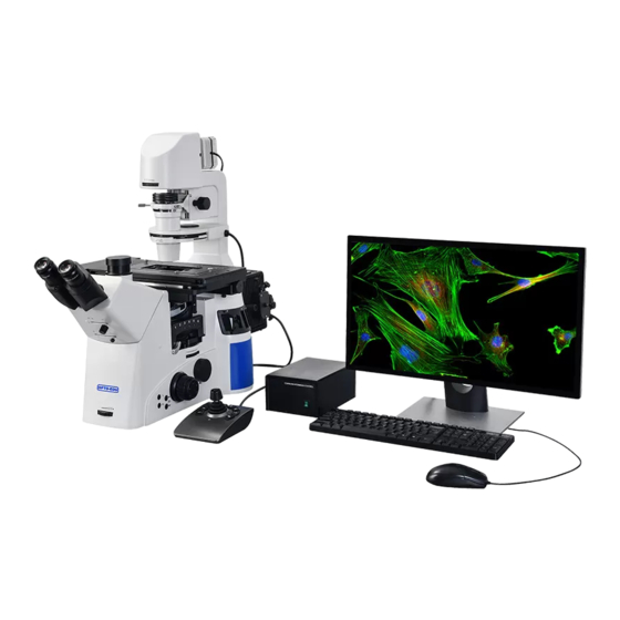
A16.1098
Full Motorized Inverted Fluorescent Microscope,
Full Auto, Semi-APO, BF+PH+FL, DF/PL/DIC
Instruction Manual
This instruction manual is applied toA16.1098 research inverted biological microscope. In order to
ensure safety, give full play to the best performance of the instrument and make you fully familiar with
the use of this microscope, we suggest that you read this manual thoroughly and carefully before
operating the microscope, and put the manual close to the workbench.
Advertisement
Table of Contents

Related Manuals for OPTO-EDU A16.1098


Summary of Contents for OPTO-EDU A16.1098
- Page 1 A16.1098 Full Motorized Inverted Fluorescent Microscope, Full Auto, Semi-APO, BF+PH+FL, DF/PL/DIC Instruction Manual This instruction manual is applied toA16.1098 research inverted biological microscope. In order to ensure safety, give full play to the best performance of the instrument and make you fully familiar with the use of this microscope, we suggest that you read this manual thoroughly and carefully before operating the microscope, and put the manual close to the workbench.
- Page 2 A16.1098 Our company provide you with the most secure and reliable instruments.However,incorrect usage and ignorance of notices in the instruction may result in damage of body and property.Please read it carefully to ensure the validity of the ways you use before you operate it.Moreover ,please put it in a place where it is convenient to read it anytime for real-time enquiry.
-
Page 3: Table Of Contents
Content A16.1098 Safety precaution ..................4 Chapter 1. Structures and Names .................7 Chapter 2. Purpose and configuration diagram ..........9 Chapter 3.Installation ....................10 3.1 Trinocular viewing head tubes ............12 3.2 Eyepieces and Centering telescope ..........12 3.3 Eyepi eces wit h cross hair............13 3.4 Transmission light stand ...............13... - Page 4 Content A16.1098 Chapter 5. Usage and Adjustment............27 5.1 Turn on the power ..............27 5.2 Adjust light intensity and switch up and down lights …….……..………..28 5.3 Light path switching ................28 5.4 Specimen placement and platform adjustment ........28 5.5 Objectives focusing and switching ..........29...
-
Page 5: Safety Precaution
Safety Precaution A16.1098 lamp house handle handle lamp house 1、Avoid storing microscope under direct sunlight or in hot location.Store it on a slash-,dust-,and vibration-free location.Ensure it on a flat, level and suitably sturdy desk or table.(Weighs about 29.5KGS) 2、 Please squeeze the carrying handle when you need to move microscope.Microscope only can be moved when there is a gap between it and... - Page 6 Safety Precaytions A16.1098 6、Connect power cord correctly and ensure that the microscope is grounded to avoid lightning strike. 7、Use the specific power cord provided by our company. 8、 Mercury lamps emit ultraviolet light which may cause injures to eyes and skin.Don’t stare at or expose your skin to the light.You’d better take some protected measures when operating microscopes.
- Page 7 Safety Precaytions A16.1098 function of the microscope or reduce the performance of the microscope. 13、If the objectives is not installed, be sure to cover the dust cover of the objective lens to prevent dust and spilled tissue culture medium from entering the system.
-
Page 8: Chapter 1.Structures And Names
Chapter 1.Structures and Names A16.1098 14、Control box 1、 Transmitted light field diaphragm 15、Power switch 2、 Filter stand 16、Reflecting field diaphragm 3、 Eyepiece 17、Reflecting aperture diaphragm 4、 Trinocular viewing head tube 18、Triple filter plate 5、 Brightness adjustment knob 19、Mercury lamp house 6、... - Page 9 Chapter 1.Structures and Names A16.1098 1、Condenser lifting hand wheel 2、Condenser centering screw 3、Rotate the hand wheel when the electric platform moves in Y direction 4、Left camera port 5、Left coarse&fine adjustment focus knob 6、Condenser reverse key 7、Condenser forward key 8、Multifunction module reverse key 9、Multifunction module forward key...
-
Page 10: Chapter 2. Purpose And Configuration Diagram
Chapter 2. Purpose and configuration diagram A16.1098 XD-2 Inverted Biological Microscope A16.1098 is mainly used to research the cell culture,tissue culture and sediment deposition in the culture plate and culture dish under transmitted light and reflected light. It can be used in observation under bright field,dark field,phase contrast,DIC,polarization,fluorescent.Mainly applications:Research on... -
Page 11: Chapter 3.Installation
Chapter 3.Installation A16.1098 Preparation before installing and performing microscope Remove the package of main body and accessories. The packages include main body,trinocular viewing head tubes.eyepieces,objectives,condenser,condenser stand,lamphouse etc,and accessories such as filters,DIC sliding plate,dust cover,tools,manual and so on.Optional attachments are packed separately 1、... - Page 12 Chapter 3.Installation A16.1098 handle handle ④ Main body Figure 1...
-
Page 13: Trinocular Viewing Head Tubes
Chapter 3.Installation A16.1098 Trinocular viewing head tubes(Figure 2) ① Use 2mm hexagonal screwdriver to loosen the mounting screw and then ball Hex screwdriver remove the dust cover. ② Calibrate the trinocular viewing tube with dovetail Trinocular joint and fix it with 2mm viewing tub hexagonal screwdriver. -
Page 14: Eyepieces With Cross Hair
Chapter 3.Installation A16.1098 ★Under the situation of zero selecting centering telescopes. zero index (white one) 3.3 Eyepieces with cross hair (Figure 4) eyepiece ametropic mounts If adding division onto correction ring eyepieces,the image reticle may slightly shift. You can rotate the adjustment... -
Page 15: Electric Platform
Chapter 3.Installation A16.1098 3.6 Electric platform setscrew (Figure7&Figure8) X-axis Electric knob ① Rotate the x-direction hand platform First mounting wheel to move the platform to screw hole the left to expose the hole as shown in the figure, and screw... -
Page 16: General Support Plate
Chapter 3.Installation A16.1098 3.7 General support plate general support plate (Figure 9&Figure 10) magnet Put the general support plate into the platform according to the drawing direction. It is suitable for glass slides and other specimens as well as Figure 9... - Page 17 Chapter 3.Installation A16.1098 Movable central support ⚫ plate part. Secure the bracket with two clamping screws (knurled screws)。 Adjust the width of the ⚫ supporting plate to match the specimen. The pallet is equipped with a ⚫ scale, which can be used as a guide for measuring width adjustment.
-
Page 18: Electric Condenser
Chapter 3.Installation A16.1098 3.8 Electric condenser (Figure 11&Figure 12) Condenser ① Align the condenser guide pin of centering screw the electric rotary table with the Guide groove Guide pin guide groove of the support, insert Set screw Transmission the condenser into the transmission... -
Page 19: Multi-Function Modes
Chapter 3.Installation A16.1098 3.10 Multi-function modes (Figure 14&Figure 15) cover pocket for analyzer Turn up the scale cover plate, ① move the locking handle downward, and pull out or insert the turntable locking from the right. reflector When inserting the module, both ②... -
Page 20: Chapter 4. Function Introduction
Chapter 3.Installation A16.1098 ④Connect the control box and the computer with the provided USB cable, and install the software provided by the company on the computer. ⑤ Plug the power cord into the power socket of the control box. 4.1 Host key function(Figure 17)... -
Page 21: Focusing Handwheel,Brightness Adjustment Handwheel
Chapter 4.Function introduction A16.1098 4.2 Focusing handwheel,Brightness adjustment handwheel(Figure 18) Moving range: 9mm Brightness adjusting hand wheel Coarse focusing hand wheel: 2mm / turn Focusing Fine tuning coke hand wheel: hand wheel 0.2mm/turn Figure 18 ★Coarse focusing hand wheels are set on both sides of the host ★The brightness adjustment hand... -
Page 22: Mediate Multiplier Nosepiece
Chapter 4.Function intoduction A16.1098 4.4 Mediate multiplier nosepiece (Figure 20) intermediate magnification converter magnification identification: 1x/1.5x/CF Magnification switched to each other. mark Magnification dial During observation, Figure 20 intermediate magnification can be directly converted to change the observation magnification for the convenience of the operator 4.5 Trinocular viewing tube... -
Page 23: Dic
Chapter 4.Function intoduction A16.1098 100%目视 0%目视 Bertrand 透镜 4.6 DIC(Figure 22) Before replacing the DIC prism, Dust cover remove the condenser and put it on Pressure ring the workbench. Remove the dust cover of the Pressure ring condenser, screw out the pressure... -
Page 24: Reflection Field Aperture And Color Filter
Chapter 4.Function intoduction A16.1098 4.7 Reflection field aperture and Control knob for visual field diaphragm color filter(Figure 23) adjustment When the transmitted light is illuminated, the dial rotates to adjust the size of the field aperture, as shown in the figure. -
Page 25: Transmission Field Of View And Aperture Dia Phragm
Chapter 4.Function intoduction A16.1098 4.8 Transmission field of view and aperture diaphragm(Figure 24) illuminated-field Move the lever up and down to adjust the size of the iris. Use a 3mm hexagon screwdriver to adjust the center of the two centering... - Page 26 Chapter 4.Function intoduction A16.1098 Turns the XY axis motion function on or off Turns the Z axis motion function on or off XY axis speed mode: fast and slow mode. Press this button to switch the mode back and forth. The two...
-
Page 27: Electric Condenser
Chapter 4.Function intoduction A16.1098 4.10 Electric condenser (Figure 26) ① Aperture adjustment: rotate aperture diaphragm dial the diaphragm and pull out the disc. ② 6 Station adjustment: rotate Figure 26 the condenser turntable. If the bright field / H is rotated into the optical path, mark "H"... -
Page 28: Chapter 5. Usage And Adjustment
Chapter 5. Usage and Adjustment A16.1098 5.1 Turn on the power(Figure 27) ①Turn on the power switch with light at the front of the control box, and the indicator light at the front of the host lights up power ②The host enters the initialization state: Figure 27 1、... -
Page 29: Adjust Light Intensity And Switch Up And Down Lights
Chapter 5. Usage and Adjustment A16.1098 5.2 Adjust light intensity and switch up and down lights(Figure 28) Brightness adjustment ①Press the TL key as shown in the figure handwheel to confirm that the upper light is on. ②Turn the brightness adjustment hand... -
Page 30: Objectives Focusing And Switching
Chapter 5. Usage and Adjustment A16.1098 ② Push the rocker to the left, right, up and down to move the platform and make the slice enter the optical path. Electrically controlled Joystick stage The stage moves in the y- Push the lever... -
Page 31: Pupillary Distance Adjustment
Chapter 5. Usage and Adjustment A16.1098 right side of the host (Fig. 33) ② The objective lens can be switched clockwise counterclockwise pressing the two keys at the rear of the right side of the host (Fig. 33).When switching the objective lens, turn the objective lens converter clockwise or counterclockwise until it clicks into place. -
Page 32: Visual Adjustment
Chapter 5. Usage and Adjustment A16.1098 the eyepiece base corresponds to the scale on the pupillary distance Interpupillary distance dot indicator to read the size of the interpupillary pupillary distance at this time. distance code 5.7 Visual adjustment ( Figure 35)... -
Page 33: Chapter 6. Objectives
Chapter 6. Objectives A16.1098 6.1 Reflective observation ◎ The following flow chart shows the basic operation steps of reflective bright field, dark field, polarized light (or cone light) and fluorescence observation. Process Operating device Pages According to the observation needs, turn on the shutter switch,... -
Page 34: Transmission Observation
Chapter 6. Objectives A16.1098 6.2 Transmission observation ◎ The following flow chart shows the basic operation steps of transmission observation, and polarization and DIC observation will be specially described later. Process Operating device Pages Turn on the shutter switch and... -
Page 35: Transmission Phase Contrast Observation
Chapter 6. Objectives A16.1098 6.3Phase contrast observation (Figure 37) ① Trinocular viewing tube--- higher and lower deflector rob Condenser -----PH1、PH2、PH3 Figure 37 Middle ratio nosepiece---1X Multi-function mode--- Transmis sion mode(Figure identity 3) Side port nosepiece----- ②The ratio of phase contrast o bjective is matched with the ma rks of condenser phase contrast. - Page 36 Chapter 6 Objectives A16.1098 c、Ensure that the matched phase contrast ring 2(in the phase contrast objective) and phase contrast ring 1(in condenser) have been moved into optical path. d 、 Observing centering telescope,adjust centering adjustment screws in figure 26 with 1.5mm hexagonal screw until centers of two phase contrast rings overlap.
-
Page 37: Dic Observation
6、Observation A16.1098 6.4 DIC observation(Figure 38) ①Trinocular viewing tube---higher deflector rob Condenser -----DIC、DICⅡ Middle ratio nosepiece---1X Multi-function mode--- DIC slider Transmission mode(Figure identity dust cover Side port nosepiece----- Figure 38 ② Condenser DIC identifiers should match with the groove of... -
Page 38: Chapter 7. Technical Specifications
Chapter 7. Technical specifications A16.1098 1、Main specifications Optical NIS60 infinite optical system (F200) System Hinged three eye observation lens barrel, 45 degree inclination, pupil Viewing Head distance 47-78mm, eyepiece interface Φ 30. Fixed visibility 1)Eye / Camera switching:(100/0,50/50,0/100) 2)Visual / Off visual / Focusable Brinell mirror Eyepiece 10×(25),EP17.5mm,Visibility adjustable - 5 ~ + 5, interface Φ... - Page 39 Chapter 7. Technical specifications A16.1098 ⚫ Indoor Use only ⚫ Altitude: 2000 meters max ⚫ Temperature:5℃ to 40℃(41℉ to 109℉) ⚫ Maximum Relatively Humidity:temperature of 31 ℃(88℉),8 0%RH,then the liner decrease. temperature of 34 ℃(93℉),70%RH temperature of 37 ℃(99℉),60%RH Operating temperature of 40 ℃(104℉),50%RH...
-
Page 40: Chapter 8.Troubleshooting List
Chapter 8.Troubleshooting list A16.1098 Even if the product functions normally, misuse can adversely affect the performance of the product. In case of any problem, confirm the contents of relevant tables in this chapter and judge the cause before requiring maintenance. If you find any problem not described in this section or the problem still exists after taking measures, please contact our sales personnel. - Page 41 Objective nosepiece is not Be sure that the objective nosepiece turned into optical path is in the right location. correctly Aperture is too big or to Small in bright field Adjust the aperture correctly observation Lens(condenser,objectives,e yepieces or petri dish) are Wipe all dirty e、Resolution...
- Page 42 Chapter 8.Troubleshooting list A16.1098 Condenser not in DIC Turn the condenser to the DIC hole position DIC slider in Insert the DIC slider into place converter not in place h、DIC effect: Confirm whether the combination of ⚫ Incomplete Incorrect DIC...
-
Page 43: Electric Part
Chapter 8.Troubleshooting list A16.1098 8.2 Electric part Problems Causes Handling a、Press the switch or button Incorrect connection Check the wiring to start the electric control device b、Initialization Incorrect connection Check the wiring is not in progress c、Power on Incorrect connection... - Page 44 After sales service commitment: If the instrument fails to work normally due to product quality problems due to human factors within 18 months from the date of delivery, the company provides free warranty and replacement parts. The company provides lifelong maintenance of products and long-term spare parts with preferential prices outside the warranty period.
Need help?
Do you have a question about the A16.1098 and is the answer not in the manual?
Questions and answers