Table of Contents
Advertisement
© 2022 TE Connectivity family of companies
All Rights Reserved
*Trademark
TE Connectivity, TE connectivity (logo), and TE (logo) are trademarks. Other logos, product, and/or company names may be trademarks of their respective owners.
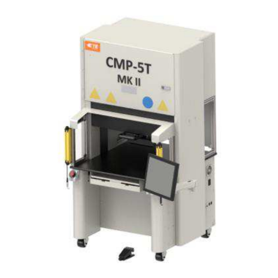
CxP Connector Press Machines CBP-5T Mk II (2216056),
CMP-5T Mk II (2216057), CMP-10T Mk II (2216058) and CSP-
5T Mk II (2216055), Operations and Maintenance Manual
SAFETY PRECAUTIONS - AVOID INJURY - READ THIS FIRST! ...................................... 3
1. INTRODUCTION .................................................................................................................. 5
2. SAFETY ................................................................................................................................ 5
Electrical ......................................................................................................................... 6
Eye/Ear Protection ......................................................................................................... 6
Safety Covers/Guards .................................................................................................... 7
Emergency Machine Off (EMO) / ESTOP ...................................................................... 7
Emergency Stop Interlocks ............................................................................................ 7
Light Curtain Interlock .................................................................................................... 7
Pneumatic System ......................................................................................................... 7
CMP Only ....................................................................................................................... 8
3. INSTALLATION ................................................................................................................... 9
CBP INSTALLATION ..................................................................................................... 9
CSP INSTALLATION ................................................................................................... 11
CMP INSTALLATION ................................................................................................... 12
4. MACHINE END OF LIFE CYCLE ...................................................................................... 13
5. PRESS OVERVIEW ........................................................................................................... 13
Purpose ........................................................................................................................ 14
Layout .......................................................................................................................... 15
Capabilities ................................................................................................................... 17
Optional Accessories ................................................................................................... 18
Machine Specific Configuration .................................................................................... 20
6. OPERATION (PRODUCTION) ........................................................................................... 21
Getting Started ............................................................................................................. 21
Operator Interface ........................................................................................................ 21
Powering Up ................................................................................................................. 21
Logging In .................................................................................................................... 22
Selecting the Board ...................................................................................................... 24
Running the Board ....................................................................................................... 25
Run Screen Buttons ..................................................................................................... 26
On Screen PCB Rendering .......................................................................................... 27
Start Pressing ............................................................................................................... 27
User Signoff ............................................................................................................... 28
Changing the Pressing Sequence .............................................................................. 28
7. PRESSING TOOLS AND FIXTURES ................................................................................ 29
Tools ............................................................................................................................ 29
PRODUCT INFORMATION 1-800-522-6752
This controlled document is subject to change.
For latest revision and Regional Customer Service,
visit our website at www.te.com.
Customer Manual
409-35001
20 NOV 20
REV C
1 of 92
Advertisement
Table of Contents

Related Manuals for TE Connectivity CBP-5T Mk II


Summary of Contents for TE Connectivity CBP-5T Mk II
-
Page 1: Table Of Contents
1 of 92 All Rights Reserved For latest revision and Regional Customer Service, *Trademark visit our website at www.te.com. TE Connectivity, TE connectivity (logo), and TE (logo) are trademarks. Other logos, product, and/or company names may be trademarks of their respective owners. - Page 2 409-35001 Support Fixtures (Platens/ Backup Fixtures) ..............29 8. PROGRAMMING & DATA ENTRY ..................30 The Tool Editor ......................30 The Connector Editor ....................31 The Profile Editor ......................33 Condition Editor ......................42 Sequence Editor ......................58 SensiPress Optimization ....................62 9.
-
Page 3: Safety Precautions - Avoid Injury - Read This First
409-35001 SAFETY PRECAUTIONS — AVOID INJURY — READ THIS FIRST! Safeguards are designed into this application equipment to protect operators and maintenance personnel from most hazards during equipment operation. However, certain safety precautions must be taken by the operator and repair personnel to avoid personal injury, as well as damage to the equipment. For best results, application equipment must be operated in a dry, dust-free environment. - Page 4 409-35001 SUPPORT CENTER CALL TOLL FREE 1-800-522-6752 (CONTINENTAL UNITED STATES AND PUERTO RICO ONLY) The Support Center offers a means of providing technical assistance when required. In addition, Field Service Specialists are available to provide assistance in the adjustment or repair of the application equipment when problems arise which your maintenance personnel are unable to correct.
-
Page 5: Introduction
This manual contains the installation, safety, operation, and maintenance procedures for the CxP press machines. This includes the Connector Benchtop Press (CBP-5T Mk II), Connector Manual Presses (CMP-5T Mk II and CMP-10T Mk II) and Connector Shuttle Press (CSP-5T Mk II). The information provided applies to all CxP presses, except where specified as applicable to certain models. -
Page 6: Electrical
409-35001 Electrical CBP/CSP Appropriate machine grounding is critical for safe operation. Therefore, an external copper ground , must be connected to the machine’s PE point. This is conductor with a minimum cross section of 2 mm located on the right-side frame and is labeled with “PE”. Be aware that electrical hazards exist where labeled. -
Page 7: Safety Covers/Guards
409-35001 Safety Covers/Guards All safety guards must be in place before operating the press. This includes all sheet metal and Lexan panels around the machine (see Figure 4). Figure 4 Emergency Machine Off (EMO) / ESTOP The Emergency Machine-Off (EMO) circuit controller monitors the safety interlocks (see interlock information below) and the computer to decide if it is safe to allow motor power and movement. -
Page 8: Cmp Only
409-35001 CMP Only The following safety items apply only to CMP models. Caster Wheels The CMP is mounted on four swivel casters. The rear two casters are lockable. Two people are required when moving the machine as it is heavy. Seismic Restraints Protection from unwanted motion during an earthquake can be achieved by bolting the frame to the floor. -
Page 9: Installation
409-35001 3. INSTALLATION This section describes the installation steps and requirements for CBP, CSP, and CMP presses. CBP INSTALLATION Uncrating The press, monitor, leveling feet, and other removed parts are shipped on one pallet, which is shrink- wrapped for protection. Remove the shrink-wrap and unpack the monitor and other shipped parts. Remove Press from pallet by unbolting hold-down bolts on four legs and lifting up with a forklift or hoist. - Page 10 409-35001 5. If the head will never move from left to right, then install the monitor on the shelf. Avoid hitting the pivot handle (see Figure 7 below). If the head will be moving, then place the monitor on the table top next to the machine.
-
Page 11: Csp Installation
409-35001 CSP INSTALLATION Figure 9 Uncrating The press, monitor, leveling feet, casters, and other removed parts are shipped on one pallet, which is shrink- wrapped for protection. Remove the shrink-wrap and unpack the monitor and other shipped parts. Remove Press from pallet by unbolting hold-down bolts on four legs and lifting up with a forklift or hoist. Put the fork lift legs underneath either side of the head assembly. -
Page 12: Cmp Installation
409-35001 Facilities Labeling The machine part number, serial number, manufacture date, and electrical specification are given on the label on the left side of the machine as shown in Figure 10. Figure 10 Electric Supply Circuit Electrical supply circuit must be 200-240VAC, 50/60Hz, single phase. Pneumatic Supply The pneumatic supply must be connected to the port provided in the machine base. -
Page 13: Machine End Of Life Cycle
Air Table. Air consumption is minimal. 4. MACHINE END OF LIFE CYCLE A decommissioned machine should be returned to TE Connectivity for proper disposal. 5. PRESS OVERVIEW This section introduces the CBP, CSP, and CMP presses. They will be collectively referred to in this manual as CxP. -
Page 14: Purpose
409-35001 Purpose The CxP servo electric press was designed for two primary purposes. First, to satisfy the increasing need for controlled quality pressing of connectors on today’s complex circuit boards. As the density of connectors increases, they become more fragile. At the same time, circuit boards have become more complex, susceptible to damage, and costly. -
Page 15: Layout
409-35001 Layout Dimension CBP-5T Mk II Width 836 mm [32.9 in.] Depth 665 mm [26.2 in.] Height 962 mm [37.9 in.] Figure 13 Dimension CSP 5T Mk II Width 836 mm [32.9 in.] Depth 665 mm [26.2 in.] Height 1775 mm [69.9 in.]... - Page 16 409-35001 Dimension CMP-5T Mk II Width 1205 mm [47.4 in.]* Depth 1176 mm [46.3 in.]* Height 1752 mm [69.0 in.] Not including monitor Figure 15 Dimension CMP-10T Mk II Width 1398 mm [55.0 in.]* Depth 1290 mm [50.8 in.]* Height 1936 mm [76.2 in.] Not including monitor Figure 16...
-
Page 17: Capabilities
409-35001 Capabilities CBP Specifics The CBP delivers a controlled force of up to 44 kN (10,000 lbs) through a 200 mm long X 37 mm wide [7.87 in long X 1.46 in. wide] “flat rock” anvil head. The Z axis travel is 50mm [1.97 in.]. NOTE A total of 160 mm [6.3 in.] of pressing space is available by installing a 50 mm [1.97 in.] adapter on the anvil. -
Page 18: Optional Accessories
409-35001 The pressing process can be controlled in one of five ways: 1. FIXED FORCE - A connector can be pressed to a set force, such as 5 kN [.56 tons/1,124 lbs]. This is a common technique used by hydraulic and pneumatic presses. It is the least sophisticated method available and is the most likely to damage the PCB or connector. - Page 19 409-35001 CMP Height Extension The CMP height extension option lifts the machine to a standing height. From table top to floor with the caster wheels measures 902mm (see Figure 17). This machine should be installed by a field engineer. Figure 17 19 of 92 Rev C...
-
Page 20: Machine Specific Configuration
409-35001 CXP Spare Parts Kit Each CXP machine part number has the option of its own spare parts kit to include extra pieces, such as light curtains or emergency stops. This kit is usually bought so that, if something breaks, it can be repaired right away. -
Page 21: Operation (Production)
409-35001 6. OPERATION (PRODUCTION) Getting Started This startup procedure assumes all necessary information has been entered in the Tool Database, Connector Database, Profile Database, Condition Database, and Sequence Database. See the programming section for details on entering data into these database tables. CBP screen examples are shown below. CMP screens are similar. -
Page 22: Logging In
409-35001 Logging In When the program is started, the main startup screen is displayed. The user will need to log in on the Operator screen prior to navigating to any other screens. Select the Operator button (see Figure 21 left) in the lower toolbar or the Operator icon (see Figure 21 right) on the right side of the upper toolbar to display the Operator screen. - Page 23 409-35001 Figure 23 Select the password entry field and enter your password using a physical keyboard or the on-screen keypad. Press “Login“ to validate the user’s credentials and complete the login process (see Figure 24). Figure 24 23 of 92 Rev C...
-
Page 24: Selecting The Board
409-35001 Selecting the Board Press the “Select Sequence” button on the lower toolbar (see Figure 25). Figure 25 Now select the sequence from the list presented. Use the scrollbar on the right side of the list to view the full list of sequences. -
Page 25: Running The Board
409-35001 Running the Board Click on the “Production” button to enter the runtime production mode (see Figure 27). If the machine axis has not yet been homed, on screen message prompts will guide you through the steps to perform this action. After pressing the on-screen “run”... -
Page 26: Run Screen Buttons
409-35001 Run Screen Buttons Depending on the access level of the person logged in, only some of the buttons may be available. The purpose of each button, from left to right, is as follows: Z Up: Used to raise the Z axis completely. After pressing this button, the press will move up to its clearance position as long as the light curtain is not broken, and the press does not encounter excessive force. -
Page 27: On Screen Pcb Rendering
409-35001 On Screen PCB Rendering The PCB rendering drawn on the screen shows the connector locations relative to each other and the board edges. The rendering is a good check for gross errors when running a new program for the first time. It will be obvious, for example, if a connector is off the board, if there is any interference between connector locations or if connector angles do not match the actual PCB layout (see Figure 30). -
Page 28: User Signoff
409-35001 Verify Tool ID - This feature requires the tool identification to be verified before pressing can proceed. It is a quality confirmation that reduces the possibility of a mismatch between what the press expects and what the operator is doing. The ID can be typed in or scanned. This feature is enabled by adding a “Verify Tool ID” condition to the Sequence. -
Page 29: Pressing Tools And Fixtures
409-35001 Insufficient Force - This error can be caused by a loose pin-to-hole interference. It can also be caused by the fixture being too thin, connector thickness problems, incorrect dimensions in the tool or connector database, or Profile program errors. The programmer should be consulted to correct the problem. Diagnostics –The “Cursors”... -
Page 30: Programming & Data Entry
409-35001 8. PROGRAMMING & DATA ENTRY The press is a highly versatile tool due to simple yet flexible programmability. Five databases are used to guide the press through specific sequences of operations. The variables stored include pressing tool physical information, pressing profile information, connector physical information, non-pressing sequence operations called “conditions”, and PCB/ backup fixture information. -
Page 31: The Connector Editor
409-35001 “Dimensions” Tool Height – The tool height information is needed in order to confirm the pressed height of the connector. Enter the height of the tool from the top surface to the plane that presses on the connector as shown in the graphic. Tool Clearance –... - Page 32 409-35001 “Number of Pins” - This is the number of pins in the connector. It is used to calculate force when using max or min force per pin in the profile. It is also used to calculate and graph the force per pin on the run time screen.
-
Page 33: The Profile Editor
409-35001 value. The Δ Force and the Δ Distance values will automatically be calculated and updated when the “Angle” or “Scale” fields are changed. “PARS” - A connector can be pressed with force that is proportional to the actual resisting force detected during the pressing cycle. - Page 34 409-35001 Figure 35 Figure 36 34 of 92 Rev C...
- Page 35 409-35001 Explanation The insertion process starts at row 1, and proceeds from there. Each row can be one of three different types: “Move to Height or Force”, “Delay”, and “Retract”. The “Move to Height or Force” type is the most commonly used step type.
- Page 36 409-35001 Navigation Tabs “Profile Step Sequence” - This tab shows the profile in a step-by-step list format. The name and details of each step are displayed in a read-only format. The “Add Step” button can be used to create a new step to be added to the profile.
- Page 37 409-35001 “Offset” – This is used in conjunction with “Height Dimension” to define the next destination of the pressing surface of the tool above the board. A positive or negative offset value can be entered to adjust the destination height to be slightly above or below the selected “Height Dimension”. (Note: this field is not used when “Custom Height”...
- Page 38 409-35001 PARS - This is a dynamic press cycle termination based on actual forces generated during the pressing process. PARS is defined as “Percent Above Range Sample” (Force Per Pin Limited). This force condition uses a special algorithm that calculates the average force generated while pressing the connector into the PCB. The “Start” and “Distance”...
- Page 39 409-35001 “Force Action” - This defines the action to be taken when the force at this step is reached. Actions are selected from the drop-down menu. The force actions are the same as the Height Actions (see Figure 42). Figure 42 “Delay”...
- Page 40 409-35001 Example: Pressing with PARS (Figure 43) Figure 43 The screen capture example shown in Figure 43 is a typical PARS press profile. The name at the left end of each line indicates the action that line will perform. In general, PARS pressing is the preferred method because it limits excess pressing force but still presses the connector to the board surface.
- Page 41 409-35001 5. This step is only reached by the “GO TO” Height Action from Step 2. It tests for a connector that simply failed to reach MinFPP by the appropriate height, by checking for 250 Newtons force detected within 0.1 mm below the MinFPP minimum height from Step 2. The speed will linearly slow to 2 mm/second by the target height.
-
Page 42: Condition Editor
409-35001 Condition Editor Purpose The Condition Editor (see Figure 45) is used to enter and store non-pressing sequence actions called Conditions in the database. A condition is a series of one or more steps containing machine actions arranged in a When/Then/Else logical format. Conditions are used in conjunction with Connectors to create the Press Sequence. - Page 43 409-35001 In example above, the condition step will continously check Digital Input DI1 to see if it has been switched on (the “When” operation). If the input is switched on before the 1 second timeout, the “When” operation evaluates to “true”, and Digital Output DO1 is turned off (the “Then” operation is executed). If Digital Input DI1 is not switched on before the 1 second timeout, the “Else”...
- Page 44 409-35001 Message Response– This input type is used to display a message to the screen via a dialog box or the production action button. This input type can also solicit a button press response from the user and will execute the “Then” operation or “Else” operation based on the users response. This input type is useful for providing status updates, querying the user, and requiring signoff from a user with elevated access rights.
- Page 45 409-35001 “Message Type”– This dropdown selects the type of message to display. The available message types are Acknowledge – This message type displays a message dialog box with a single “OK” button for the user to acknowledge the message. Query – This message type displays a message dialog box with a “Yes” button and a “No”...
- Page 46 409-35001 Clearance Move– This input type is used to move to the tool clearance height of the currently loaded connector press independent from the currently loaded press (when a press step is executed, the press will move to tool clearance or prompt the user to move to tool clearance by default).
- Page 47 409-35001 “COM Port Settings”– This button opens the “When” COM Port Settings window (see Figure 48) where communication settings for the COM port device can be entered. Selecting “OK” will store the settings entered, and selecting “Cancel” will discard changes to the settings. Figure 48 “Port Number”–...
- Page 48 409-35001 “Trigger On Command”– (Only used when “Use Serial Trigger” enabled) This entry field specifies the character sequence that will be sent to the COM port device to trigger or query the device to start sending data. “Trigger Off Command”– (Only used when “Use Serial Trigger” enabled) This entry field specifies the character sequence that will be sent to the COM port device to stop the device from sending data after a read is complete.
- Page 49 409-35001 length. For example, if a “4” is entered into this field, the start character number is “3” and the data string “SN123456” is read from the device, the parsed substring would be “1234”. “Data Received” / “Data Received Matches Substring”– This toggle selects how the “When”...
- Page 50 409-35001 “Command Settings” – This button opens the “When” PPS Settings window (see Figure 50). This window is used to set how the “When” operation should evaluate to “true” and which command data to send for “Set” PPS commands. The settings options will vary base on the “Command”...
- Page 51 409-35001 Pin State Selector– (Only available for “Set Pin Mask” command and for “Get Pin States”, “Get Pin Mask” commands when “Response Data Meets Condition” is selected) This tab allows the user to specify what type of pin data the “When” operation will look for to evaluate to “true”...
- Page 52 409-35001 Figure 51 “Then” and “Else” boxes – Entries within these boxes define and describe the “Then” and “Else” output operations of the current condition step. The “Then” operation will occur if the “When” operation evaluates as “true”. The “Else” operation will occur if the “When” operation evaluates as “false” or times out.
- Page 53 409-35001 Close Messages – This message type closes any open message dialog boxes on the screen. Clear Action Button – This message type clears any specialized messages (messages displayed using a “Condition”) from the production “Action” button and status box. “Message Class”–...
- Page 54 409-35001 “Baud Rate”– This entry field specifies the baud rate in kbps to use when communicating with the COM port device. “Data Bits”– This entry field specifies the number of data bits contained in each message frame sent to the COM port device. “Stop Bits”–...
- Page 55 409-35001 Clock Icon Button– This button opens the “Then”/”Else” Time Settings window. If no settings are entered in this window, default “Duration” values will be used based on the “Output Type” selected. “Duration” – This entry field specifies the time in milliseconds that the operation will executed the output operation.
- Page 56 409-35001 One common modification to the “Measure Board Thickness” condition is toggling the “Execute Once Per Batch” option (see Figure 54) on or off based on how often board thickness should be measured for the users application. Toggling the option off will cause board measurement to occur for every board pressed.
- Page 57 409-35001 To modify the standard PCB Verify condition, “Copy” the condition, rename it, and save it under a new name. Open the “COM Port Settings” window by pressing the corresponding button in the “When” operation box (see Figure 56). Select the appropriate “Port Number” (see Figure 57) for the barcode scanner being used (the list of available COM Port devices can be refreshed on the system settings screen).
-
Page 58: Sequence Editor
409-35001 For example, assume the format of the model numbers being scanned is “PCB_XXXXX_MODEL” and the correct board model number is “45612”. This means the correct model number string will be “PCB_45612_MODEL”. The portion of the model number string that must be parsed out starts at character number 5, so “5”... - Page 59 409-35001 “Revision” - This is the revision level of the board to be pressed, or alternatively the revision of the Press Sequence program. It is used as reference in this file only. Board Dimensions Tab “Board Width” - This is the dimension of the board in the X axis direction (left to right) as normally positioned in the machine.
- Page 60 409-35001 “Connector Drag Enabled/Disabled” – Toggle this button to “Enabled” to allow the user to drag and drop connectors in the part viewer to set their x and y location on the board. To prevent accidental modification of connector locations, toggle the button to “Disabled”. Settings Tab “Fixture Thickness”...
- Page 61 409-35001 “Start Sequence Automatically” – When this feature is checked, the press sequence will start automatically upon enter the “Production” screen. This feature is typically used for most multi-connector pressing sequences in order remove the extra button press needed to start each board pressing sequence.
-
Page 62: Sensipress Optimization
409-35001 Move Step Up Button (Up Arrow Icon) – Press this button to swap a step with the step preceding it in the press sequence. Move Step Down Button (Down Arrow Icon) – Press this button to swap a step with the step after it in the press sequence. - Page 63 409-35001 The bent pin detection works the same way. It detects bent pins (or improperly pre-seated connectors) by looking for a low force value at a height range that is just above where the anvil normally makes contact with the tool and begins to build force. There is no new or special analysis associated with SensiPress.
- Page 64 409-35001 Profile Set Up (reference Figure 65) 1. Add Line 1 to the current connector Profile. The force for this line can be 25-50 lbs. 2. Make sure that Line 1 Unseated Tool Top +.xxxx value is at least .0500 greater than the Tool Clearance height (in Tool Editor).
- Page 65 409-35001 No Bent Pin (reference Figure 66) Figure 66 Adjust “Unseated top Tool + x.xxx” dimensions in Line 1 and Line 2 as needed to set the early contact zone to defect force just before the curve starts. A few test presses with no bent pins may be needed to tune the profile correctly.
- Page 66 409-35001 Other Factors Because the bent pin detection is reliant on looking for a very small force in a narrow height range, anything that can have an impact on the overall stack height will influence reliability and functionality. Therefore, customers will want to eliminate sources of variation as much as possible. Figure 68 ...
- Page 67 409-35001 Board Thickness Tolerance For optimal performance, PCB thickness variation should be minimal. If too large, the performance would be inconsistent. If excessive PCB thickness variation is a potential, use the Measure Board Thickness option in the press data editor to verify the thickness of the PCB. Figure 70 Tooling and Fixture Match Up It is not recommended to use seating tools and fixtures interchangeably.
-
Page 68: Diagnostics Screen
409-35001 9. DIAGNOSTICS SCREEN The press software provides maintenance utilities on the Diagnostics Screen as described below. The Diagnostics screen is found under the System drop-down menu. Manual Control Panel The Manual Control panel (see Figure 72) is used for servo setup, maintenance and troubleshooting purposes. The left panel provides the joystick controls for manually operating the servo axis. -
Page 69: Inputs/Outputs Tab
409-35001 Inputs/Outputs Tab The Inputs/Outputs tab is provided for diagnostic purposes and is shown on the right half of the diagnostics screen. The “Inputs” subpanel (see Figure 72) shows the status of all available standard non-safety digital inputs. A green indicator icon with a check mark signals an “on” condition for the given input and a red empty signals an “off”... -
Page 70: Load Cells Panel
(force) calibration function (see Figure 77) as well as showing information on the most recent calibration performed (see Figure 79). NOTE TE Connectivity also offers a load cell calibration service. The height calibration functions are located under the “Height” subpanel in the Calibration Panel. Figure 76... - Page 71 409-35001 Figure 77 71 of 92 Rev C...
- Page 72 409-35001 Figure 78 Figure 79 72 of 92 Rev C...
- Page 73 409-35001 Figure 80 The “Get Limits” button initiates a sequence to find the limit switch positions and set the upper and lower motion limits to an appropriate distance from the switch positions. The “Calibrate Height” button will run a motion sequence which will exert the amount of force specified in the “Block Force” entry field on a height spacer block to calibrate the axis position relative to the surface of the machine table.
- Page 74 409-35001 The force calibration functions are located under the “Force” subpanel in the Calibration Panel. To perform force calibration, you must be logged in as TE Administrator. Prior to force calibration, the ACAL unit must be connected to the USB-RT connection on the machine and the digital readout must be connected to ACAL load cell and powered on.
- Page 75 409-35001 Figure 82 Figure 83 75 of 92 Rev C...
-
Page 76: Data Utilities
409-35001 Figure 84 Figure 85 10. DATA UTILITIES Message Viewer The “Message Viewer” screen (Figure 86) is located under the System drop-down menu. The message viewer allows the user to view the history of the last 1000 messages sent between the Human-Machine Interface (HMI) and middleware portion of the software. - Page 77 409-35001 The text box at the top of the “Message Viewer” screen can be used to send custom messages to the middleware from the HMI for diagnostic purposes. This can be used to replay a series of actions carried out by the user.
-
Page 78: Machine Logs
409-35001 Machine Logs The “Log Viewer” screen (see Figure 87) is located under the System drop-down menu. The “Log Viewer” screen allows viewing of the various log files related to machine operation. The “Search” text entry field can be used to search the list of “Log Files” by name. An entire log file can be viewed, or only a portion of the log can be loaded. -
Page 79: Setup Utilities
409-35001 11. SETUP UTILITIES System Settings The “System Settings” screen is accessed via the System drop-down menu and is used for setting the machine configuration and other miscellaneous parameters as described below. Localization Settings Distance Units – set the HMI to display distance as either millimeters or inches. ... - Page 80 409-35001 Machine Configuration The Machine Configuration tab (see Figure 89) contains various parameters used to define certain aspects of machine motion and has options to enable or disable certain machine functionality. After updating the machine configuration, the “Save Machine Configuration” button must be pressed to save the current configuration to machine database.
- Page 81 409-35001 Database Backup and Restore The Database Backup and Restore tab (see Figure 90) contains buttons to manage the user and machine databases. To backup the user database use the backup user database file browser to select a file location to save the database backup to, and press the “Backup User Database” button. To restore the user database from a previous backup, use the restore user database file browser to select the database to restore from and press the “Restore User Database”...
-
Page 82: User Access
409-35001 User Access User access to the various machine functions is controlled by password protected individual user accounts. To create a new user, an individual with Administrator Access permission must log in and use the “Add Operator” button on the “Operator” screen. A new user’s access will be limited base the “Operator Type” selected when creating a new user. - Page 83 409-35001 Fill in the operator name, the password, and select the operator type from the drop-down menu, which defines which screens and features the user will able to access. The available operator types or access levels are (in hierarchical order) “Administrator”, “Maintenance”, “Technician”, “Inspector”, “Operator” and “Restricted Operator”...
-
Page 84: Network Viewer
409-35001 Network Viewer The Network Viewer screen (see Figure 93) displays information about the connection from the HMI (Human Machine Interface) computer to the rest of the machine software. Information about any MES machine connections can also be viewed here. Figure 93 Beckhoff Configuration The Beckhoff Configuration screen displays information about the Beckhoff PLC controller used in the machine. -
Page 85: Pps Viewer
409-35001 PPS Viewer The PPS Viewer screen provides access to all available PPS tool commands for setup and troubleshooting. The PPS Viewer screen will only be available if PPS is enabled for the machine. The “Basic Commands” tab (see Figure 95) provides access to the most commonly used PPS commands. These commands are used to view pin states and setup the pin mask(s) for the tool. - Page 86 409-35001 The “Advanced Commands” (see Figure 96) provides access to commands to view information about the PPS tool and about the tool setup. Figure 96 The “Setup Commands” tab (see Figure 97) provides access to commands for setting up PPS tool or PPS tool circuit board.
-
Page 87: Preventive Maintenance
409-35001 12. PREVENTIVE MAINTENANCE The press has been designed to minimize maintenance as much as possible. The following preventive maintenance procedures should be done on the intervals given below. An annual inspection, adjustment, and calibration service is offered by TE. DANGER Always turn off the main power switch and disconnect the electrical cord from the power source when performing maintenance on the press. -
Page 88: Pm Schedule
409-35001 PM Schedule Figure 98 provides a preventative maintenance schedule for these machines. ITEM DAILY WEEKLY QUARTERLY YEARLY ● Blow Machine Off ● Wipe Machine Down ● Inspect Wires and Hoses ● Oil as Indicated Above ● Torque Head Bolts ●... - Page 89 409-35001 APPENDIX A – SPARE PARTS CBP Spare Parts List TE PART NUMBER DESCRIPTION REVISION 2216172-1 KIT, SPARE PARTS CBP NOTES: ● Identify kit per TE Specification 115-67-12 (part number, revision letter, and country of origin) ● Kit 2216172-1 is used with all top level CBP configurations (refer to drawing 2216056) CSP Spare Parts List TE PART NUMBER DESCRIPTION...
- Page 90 Missing connector detection Clean & Quiet Energy efficient CE Compliant Specifications CBP-5T Mk II Force: 44 kN [5 ton] Force sensitivity: 50 N [12 lbf] Z axis travel: >50 mm [2 in.] Z axis speed: up to 8 mm [.31 in.]/sec ...
- Page 91 409-35001 CMP-10T Mk II Force: 106 kN [12 ton] Force sensitivity: 100 N [23 lbf] Z axis travel: >130 mm [5 in.] Z axis speed: up to 19 mm [.75 in.]/sec Power: 200-240 VAC, 1 Phase, 10 A ...
- Page 92 409-35001 APPENDIX C – ELECTRICAL/MECHANICAL SCHEMATICS CBP-5T, CMP-5T, AND CMP-10T TE DWG NUMBER DESCRIPTION REVISION 2216706 SCHEMATIC, ELECTRICAL CSP-5T TE DWG NUMBER DESCRIPTION REVISION 2216052 SCHEMATIC, ELECTRICAL 92 of 92 Rev C...
Need help?
Do you have a question about the CBP-5T Mk II and is the answer not in the manual?
Questions and answers