Table of Contents
Advertisement
Quick Links
© 2017 TE Connectivity Ltd.family of companies
All Rights Reserved
*Trademark
TE Connectivity, TE connectivity (logo), and TE (logo) are trademarks. Other logos, product, and/or company names may be trademarks of their respective owners.
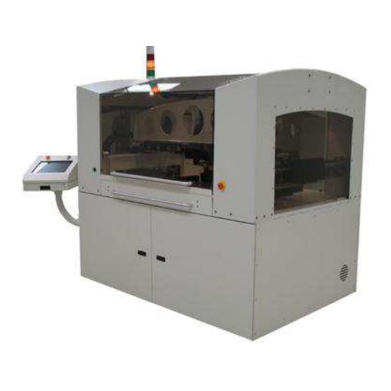
CAP-6T and CAPI-6T
Automatic Electric Press
6-Ton Operations Manual
SAFETY PRECAUTIONS - AVOID INJURY - READ THIS FIRST! ...................................... 2
1. INTRODUCTION .................................................................................................................. 5
1.1.About This Manual ......................................................................................................... 5
1.2.Press Overview .............................................................................................................. 5
1.3.Production Details .......................................................................................................... 6
1.4.General Specifications ................................................................................................... 6
1.5.Capabilities ..................................................................................................................... 6
1.6.Layout ............................................................................................................................ 8
2. SAFETY ................................................................................................................................ 8
2.1.Equipment Lockout ........................................................................................................ 8
2.2.Emergency Machine Off (EMO) / ESTOP ...................................................................... 9
3. INSTALLATION ................................................................................................................... 9
3.1.Shipping ......................................................................................................................... 9
3.2.Uncrating ........................................................................................................................ 9
3.3.Initial Assembly .............................................................................................................. 9
3.4.Facilities Labeling ......................................................................................................... 10
3.5.Electric Supply Circuit .................................................................................................. 10
4. OPERATION ...................................................................................................................... 10
4.1.Operator Interface ........................................................................................................ 10
4.2.Logging On ................................................................................................................... 10
4.3.Selecting the Board ...................................................................................................... 11
4.4.Running the Board ....................................................................................................... 11
4.5.On Screen PCB Rendering .......................................................................................... 12
4.6.Interrupting the Pressing Cycle .................................................................................... 12
4.7.Changing the Pressing Sequence ................................................................................ 12
4.8.Error Conditions ........................................................................................................... 13
4.9.Runtime Help Screen ................................................................................................... 13
5. PROGRAMMING AND DATA ENTRY ............................................................................... 14
5.1.The Tool Data Base Editor ........................................................................................... 14
5.2.Profile Editor ................................................................................................................. 15
5.3.The Connector Editor ................................................................................................... 21
5.4.The Press Sequence Editor ......................................................................................... 24
6. SPC Option ........................................................................................................................ 27
6.1.Overview ...................................................................................................................... 28
6.2.Process Data ................................................................................................................ 28
PRODUCT INFORMATION 1-800-522-6752
This controlled document is subject to change.
For latest revision and Regional Customer Service,
visit our website at www.te.com.
Customer Manual
409-32048
18 MAY 17 REV A
Continued
1 of 64
Advertisement
Table of Contents

Related Manuals for TE Connectivity CAPI-6T


Summary of Contents for TE Connectivity CAPI-6T
-
Page 1: Table Of Contents
1 of 64 For latest revision and Regional Customer Service, All Rights Reserved *Trademark visit our website at www.te.com. TE Connectivity, TE connectivity (logo), and TE (logo) are trademarks. Other logos, product, and/or company names may be trademarks of their respective owners. - Page 2 7. PRESSING TOOLS ......................30 7.1.Insertion Tools ......................30 7.2.PCB Support – CAP-6T (Drawer Loaded Press) ............31 7.3.PCB Support – CAPI-6T (Conveyor Loaded Press) ............ 32 8. AUTOLOAD OPTION FOR THE CAPI-6T ................. 34 8.1.Configurations ......................35 8.2.Operation ........................36 8.3.Testing the Autoload Function ..................
-
Page 3: Safety Precautions - Avoid Injury - Read This First
Actuate the machine Disconnect Switch. Use lock-out / tag-out device on the machine Disconnect Switch. Unplug / switch off machine Power from power source. Seek immediate medical attention, if required. Contact TE Connectivity Support Center 3 of 64 Rev A... - Page 4 409-32048 SUPPORT CENTER CALL TOLL FREE 1-800-522-6752 (CONTINENTAL UNITED STATES AND PUERTO RICO ONLY) The Support Center offers a means of providing technical assistance when required. In addition, Field Service Specialists are available to provide assistance in the adjustment or repair of the application equipment when problems arise which your maintenance personnel are unable to correct.
-
Page 5: Introduction
Machine) and CAPI-6T (Conveyor Machine) 6 ton Automatic Electric Press. See Figure 1. 1.2. Press Overview The CAP (designates commonality of the CAP-6T or CAPI-6T) all electric automatic servo press was designed for two primary purposes. First, to satisfy the increasing need for controlled pressing of connectors on today’s complex circuit boards. -
Page 6: Production Details
Manufacturer: TE CONNECTIVITY Berwyn, PA 19312 Machine Title: CAP-6T Drawer Machine (P/N 1689700-1) CAPI-6T In-line Conveyor Machine (P/N 1689700-2) CAPI-6T Shuttle Machine (P/N 1689700-3) Machine Function Compliant pin connector press. Machine Usage The CAP is an automatic stand-alone unit that presses compliant pin connectors into a printed circuit board (PCB). - Page 7 409-32048 For the CAPI-6T, the PCB length & width is adjustable: Length 60 mm to 860 mm [2.36 to 34 in.] Width 76 mm to 712 mm [3 to 28 in.] Thickness 1.5 mm to 6 mm [0.06 to 0.31 in.] With alternate clamps, the thickness is 4.00 mm to 10 mm [0.15 to 0.39 in.].
-
Page 8: Layout
409-32048 1.6. Layout The press is a four-axis servo controlled machine. The pressing head moves 94 mm [3.70 in.] in the Z direction at speeds up to 45 mm [1.8 in.] per second. The press head assembly is driven by linear servo motors from side to side 914 mm [36 in.] and front to back 762 mm [30 in.] at a velocity of 1 m [39.4 in.] per second. -
Page 9: Emergency Machine Off (Emo) / Estop
409-32048 2.2. Emergency Machine Off (EMO) / ESTOP The Emergency Machine Off / Emergency Stop switches are mounted on the front and back of the press. They are clearly marked. When pressed, the switch latches in the pressed state and must be twisted to release. The EMO circuit is a hardware-based (dry contact) latching circuit that does not reset when the EMO switch is released. -
Page 10: Facilities Labeling
409-32048 3.4. Facilities Labeling The electrical requirements are given on the label on the right-rear side of the machine. See Figure 5. Figure 5 3.5. Electric Supply Circuit Electrical supply circuit must be 208-230 VAC, 25 Amp, 1-phase, 50/60 Hz. 4. -
Page 11: Selecting The Board
409-32048 Select your name from the list displayed (if your name does not appear on the list you must see the system manager to add it). See Figure 8A and 8B. Operator Log-On Screen (Enter Your Password and Press “OK” Password Entry Screen Figure 8 4.3. -
Page 12: On Screen Pcb Rendering
409-32048 Depending on the access level of the person logged in, only some of the buttons will be available. The unavailable buttons are not shown. The purposes of the buttons from left to right are as follows. “Z Up” - Used to raise the Z axis after a normal cycle is interrupted. An interruption can be caused automatically by an error condition, or manually by pressing the green START/PAUSE button or the STOP icon on the screen. -
Page 13: Error Conditions
409-32048 4.8. Error Conditions Some of the common error conditions encountered during pressing are detailed below. The error conditions generated by the Profile program are user defined, so the wording can vary. In addition, new error conditions not covered here may be introduced. Premature Contact - This error is generated by the Profile program and is likely to be the most common error condition that is encountered during normal operation. -
Page 14: Programming And Data Entry
409-32048 Runtime Help Screen Figure 11 5. PROGRAMMING AND DATA ENTRY The press is a highly versatile tool due to the built in programmability. Four data bases (accessed through “editors”) are used to guide the press through specific sequences of operations. The variables stored include pressing tool information, pressing profile information, connector information, and PCB information. -
Page 15: Profile Editor
409-32048 The editor can be accessed from the icon at the bottom of the screen. The following fields are maintained in the data base. Entries “Tool Name” - This is a name you choose up to 20 characters long, spaces allowed, that will be used to refer to this tool in the future. - Page 16 409-32048 Explanation The editor provides up to 20 steps, numbered at the left of the screen, to be entered for a given profile. The insertion process starts at row 1, and proceeds from there. Each row has two “events”. “Height Above the Board”...
- Page 17 409-32048 Figure 14 “Height Action” - This defines the action to be taken when the height at this step is reached Actions are selected from the drop down menu shown in Figure 15. The available actions are: Figure 15 — Next Step - This directs the process to the next step below. —...
- Page 18 409-32048 PARS-FPPL is an abbreviation of “Percent Above Range Sample - Force Per Pin Limited”. This force condition uses a special algorithm that calculates the average force generated while pressing the connector into the PCB. The “Start” and “Distance” boxes in the middle of the screen define the bounds for the average.
- Page 19 409-32048 The speed starts at “Run Speed” (entered in the “Servo Parameters” edit screen) and changes linearly (“ramps”) down to the speed given in step 1. When step 1 is reached, the speed begins ramping down to the speed given in the next step processed. This will generally be step 2, but not if a “Go To” action programmed in step 1 is executed.
- Page 20 409-32048 1. Move the head from the tool clearance height (as given in the Tool Database) down to .030 in. above the unseated top of tool. The speed will ramp linearly from the press “Run Speed” to .300 in. per second.
-
Page 21: The Connector Editor
409-32048 5.3. The Connector Editor Purpose The Connector Editor is used to enter and store physical data for the connectors. The data is stored in an Access Database file. See Figure 23. Connector Editor Screen Figure 23 Entries “Connector” - This is a name you give to the connector. It can be anything you choose, but is usually a descriptive name or manufacturer’s part number. - Page 22 See Figure 24. TE Connectivity recommends using the same parameters for SPC Range as are entered for the PARS Sample Range in the Connector Editor. This is due to the similarity of the force sample location necessary for both.
- Page 23 409-32048 LIMITS – The SPC “Min Force (Range)” and “Max Force (Range)” Limits are specification limits, which the press force is compared against to determine if the press is good (within the limits) or bad (outside the limits). These spec limits will affect CPK (process capability index). Of course, the wider these limits the better the process capability appears.
-
Page 24: The Press Sequence Editor
409-32048 5.4. The Press Sequence Editor Purpose The Press Sequence Editor (Figure 25) is used to enter and store the data about the board including board physical data and connector information. All connectors to be used on the board being programmed must be defined in the connector data base before the press data file can be generated. - Page 25 409-32048 “Fixture ID” – The fixture may be identified with an ID number. If a value is entered in this field, the user will be prompted to verify the correct fixture ID when the cycle is started. This entry is not required. “No.
- Page 26 409-32048 Datum. Remember that the X direction is always defined as left to right with the board mounted in the press. See Figure 26. “Datum Board Frame Coordinates” – It is the coordinate value of the Datum described above in relation to the board’s origin point (the point from which X &...
-
Page 27: Spc Option
409-32048 From Run Screen Graphic Example of the Step & Repeat Command Line Figure 27 The step for each PCB is the distance from the main PCB 0,0 to the new PCB 0,0. The X direction step distance is entered in the X column, and the Y distance in the Y column. To complete the step & repeat entry, select the “STEP &... -
Page 28: Overview
409-32048 6.1. Overview Raw data for the average force per pin for each connector pressed is maintained in a file with the same name as the connector, with a .RAW extension. SPC information is calculated from the raw data and displayed on command. -
Page 29: Options
409-32048 Figure 30 Point - The plotted point number. Xbar - The average force for all connectors of the charted type on the current board. Var - The force variability for all connectors of the charted type on the current board. May be R (range) or S (std. -
Page 30: Pressing Tools
409-32048 Print - Press this button to print the charts on a printer. The printer driver must be installed using the standard windows method. 7. PRESSING TOOLS This section defines general requirements for connector pressing tools that will be used in the CAP. In many cases, insertion tools used in manual pressing operations can be adapted to the CAP. -
Page 31: Pcb Support - Cap-6T (Drawer Loaded Press)
409-32048 7.2. PCB Support – CAP-6T (Drawer Loaded Press) Support Fixture Plate (Figure 33) The press uses a custom fixture specific to the PCB to support the board during the pressing cycle. The fixture is located on the fixture support plate (a pull-out “drawer” style support) for ease of installation and removal. -
Page 32: Pcb Support - Capi-6T (Conveyor Loaded Press)
— PCB Clamp – Each fixture should provide a means to clamp the PCB down. This prevents the PCB from being lifted when an insertion tool is retracted from a pressed connector. Also, the clamp holds the PCB flat to the fixture. 7.3. PCB Support – CAPI-6T (Conveyor Loaded Press) Support Fixture Plate (Figure 34) The press uses a custom fixture (similar to that used on the CAP-6T) specific to the PCB to support the board during the pressing cycle. - Page 33 409-32048 the PCB to clear the fixture when the PCB is conveyed. The conveyor will lift the PCB up 25 mm [.98 in.]) before it conveys the PCB. This maximum height as measured from the fixture support plate to the conveyor belt is 55 mm [2.17 in.]. Flatness and parallelism of top and bottom surfaces of the fixture should have a maximum run-out of 0.13 mm [.005 in.].
-
Page 34: Autoload Option For The Capi-6T
The Autoload option used with an adjustable width conveyor will allow either in-line or stand-alone operation and increases the throughput capabilities of the CAPI-6T over the CAP-6T. PCBs are loaded and secured automatically. Once a press sequence has completed, the Autoload conveyor unloads the PCB. See Figure 37. -
Page 35: Configurations
8.1. Configurations In-Line The CAPI-6T Autoload option allows the press to be incorporated into a SMEMA left-to-right automated PCB processing line (Production mode) and a SMEMA right-to-left automated PCB processing line (Reverse Production mode). Changing modes requires a software configuration change and that the SMEMA cables be exchanged from side to side. -
Page 36: Operation
NOTE If desired, the CAPI-6T with Autoload option configured for In-line operation may also be operated as a stand alone press if Conveyor Extensions are attached on both sides. -
Page 37: Other Operating Functions
409-32048 NOTE Most of the controls on the IO Autoload tab require machine power for correct operation. The Machine Enable control on the ‘Safety’ tab should be activated before selecting the IO tab. Basic manual Autoload functions are available on the IO Screen Autoload tab for use during part setup or to allow clearing a conveyor jam. - Page 38 409-32048 In other modes, the state of these buttons (outputs) is controlled by the main conveyor controller (mounted under the tabletop). The input displays are always active. 2. The Run motor button turns the main conveyor belt motor on and off. The Reverse direction button toggles the belt direction from left-to-right to right-to-left (reverse).
-
Page 39: Setup Autoload Width
To manually adjust the Autoload conveyor width, perform the following steps. Refer to Figure 41. 1. Open the right front door on the CAPI-6T base to access the conveyor width hand crank. 2. Go to the Autoload tab on the Joystick screen to access the manual conveyor functions. -
Page 40: Autoload Conveyor - Maintenance
Joystick Screen – Autoload Tab Figure 41 8.6. Autoload Conveyor – Maintenance Features on the CAPI-6T Autoload system that may require periodic visual checks have been listed below. See Figure 42. Check Guide Rods, Y axis (PCB width) bearing guide rails, conveyor belts, and all other areas of motion for foreign matter (dust, dirt, metal shavings, etc.). -
Page 41: Conveyor Extension - Autoload Option
The extension is a simple edge guide belt conveyor mechanically connected to the CAPI-6T main or infeed conveyor rails and belt motor. The CAPI-6T conveyor input or exit sensors are moved to the end of the extension rails. The extension has no electrical controls or components. -
Page 42: Installation
11. Measure the distance (in millimeters) from the fiber sensors at the PCB load position of the CAPI-6T to the new position of the fiber sensors at the exit of the conveyor extension. On the CAPI-6T screen, go to the Autoload tab of the I/O screen and change the Fiber-Fiber distance for the main conveyor to match the measured distance. -
Page 43: Operation
Conveyor Extension Drive Coupling Figure 45 9.2. Operation When attached to the CAPI-6T conveyor, the Conveyor Extension operates as an integral part of the machine conveyor. Once properly installed, no additional actions are required to operate the CAPI-6T with extension(s). 43 of 64... -
Page 44: Preventative Maintenance (Pm)
409-32048 10. PREVENTATIVE MAINTENANCE (PM) The press has been designed to minimize maintenance as much as possible. Preventive maintenance should be done on the intervals given below. 10.1. Cleaning All surfaces should be kept clean and free of dust buildup. Wipe down all exposed flat surfaces with a soft rag. Using light air pressure, blow the press head, tool rack(s), and structure areas clean from the top down periodically. -
Page 45: Machine Zero
409-32048 11.3. Machine Zero Since the pressing process is data driven, each axis must be properly zeroed before using. If any motor or encoder is removed or loosened, re-zeroing will be necessary. Figure 47 Z-axis Zero The Z-axis zero point is defined by the relationship between the X/Y-axis surface plane that the support fixture rests on and the lower surface of the tool holder that is in the press head tool holder. -
Page 46: Sequence Of Operation
The following sequence is for a CAPI-6T with the Autoload option that is manually loaded and unloaded in Reverse Shuttle mode. This sequence is provided to indicate to the Operator the flow of material through the press. -
Page 47: Machine Logs
409-32048 1. The operator will populate a PCB with compliant pin components outside the CAPI-6T. 2. As soon as the operator is clear and the access doors are closed, the press cycle can start. 3. The press shall stop instantaneously if the press area is intruded upon. -
Page 48: User Log
409-32048 Figure 49 14.2. User Log The user log is automatically appended every time there is a log in or out event. Data covering Selected Dates can be viewed, or All can be chosen. See Figure 50. The user log can be purged by selecting the data period that you would like to save, then pressing Update User Log. -
Page 49: Additional Screen Reference
409-32048 15. ADDITIONAL SCREEN REFERENCE Each of the screen images shown on the following pages (Figures 51 through 66) are followed by a brief description. Initial AEP Screen Initial AEP Screen This screen is displayed when the main press program is initiated from the Windows desktop. The only action available is the Operator button, which will initiate the Operator Access Screen on the next page. - Page 50 409-32048 Qualified Operators This screen allows the Press to be activated by any number of qualified Press Operators. If there are a substantial number of people authorized to use the Press, additional sheets can be accessed by the Page Up or Page Down buttons or the Alphabetical Tabs located on the top of the screen.
- Page 51 409-32048 Operator Password The Password Entry Screen allows the operator selected on the previous page to enter his/her individual Password. Enter Password by using the screen buttons (cursor or touch), then press the OK button. Figure 53 51 of 64 Rev A...
- Page 52 409-32048 Main Screen The Operator activated Main Screen allows the Operator access to Press functions as authorized by the designated machine administrator. In most cases, a standard operator will only have access to the Run button. Technicians could be allowed, at Supervisor discretion, the ability to access the Joystick screen for manual operation and various Setup and Editor screens.
- Page 53 409-32048 User Access Input If the Administrator or Lead Technician needs to add another operator or modify an existing operator, this Main Menu option allows that individual to be entered into the database of qualified people. The individual inputting new user information is limited by their level of access, and can only extend that level or below to the new user.
- Page 54 409-32048 New User Access This screen allows access level entry or modification for an operator. Select the desired access boxes depending on Administrative discretion. The Administrator or Superman symbol allows access to all screens and editors. Note: the level of access is limited by the level of the operator currently logged on. ‘Temporarily Disqualify’...
- Page 55 409-32048 Joystick: Analog / Position Input The ‘Joystick’ Pad on the upper right controls Press Head travel in the X, Y, and Z axes. The Sliders on the side of the Joystick indicate actual positions of the Press Head. The X-axis indicates the movement side to side of the Press Head. The Y-Axis indicates the ‘Gantry’...
- Page 56 409-32048 Joystick: X / Y /Z Position points The Joystick pad and associated controls remains the same on the right-hand side. This screen allows you to create preprogrammed X / Y / Z positions that, with the appropriate button push, will bring you to the correct coordinates. The safety feature is the Move button; you activate the desired position but the Press Head will not move until the Move button is depressed.
- Page 57 409-32048 Joystick: Speed & Force control Controls remain the same on the Right hand side. These slider controls are self-explanatory. They control the maximum programmed speed in the X / Y / Z Axis that the Joystick can give you in Jog mode or programmed motion can generate. Maximum Joystick generated force is controlled by the bottom slider.
- Page 58 409-32048 Joystick: Tools The Joystick (right side of the screen) remains the same. The purpose of this screen is to insert or remove press tools to/from the Tool rack. The sliders govern which tool (by slot number) the loading mechanism will go to load / replace the press tool. It can be programmed, by check box, to ‘auto search’...
- Page 59 409-32048 Joystick: Machine Zero Joystick Functions (Right side of the screen) remain the same. This screen is used to set up the actual Machine Zero (0, 0) of the coordinate system used by the motion control system. This should only be performed by qualified personnel. Figure 61 59 of 64 Rev A...
- Page 60 409-32048 Joystick: Calibration Controls on the right side of the screen are the same as before. The left side controls are used for automatic calibration of the load cells using the ACAL unit load cell standard. This calibration is performed initially at the factory. It is recommended to perform annual calibration.
- Page 61 409-32048 Digital I / O Screen This screen is used to access the digital inputs and outputs used by the machine. The status of the inputs can be viewed and the Outputs can be manually activated. This screen is very useful in troubleshooting sensor adjustment, shot pin functioning, and fixture table action.
- Page 62 409-32048 Servo Terminal This is for the advanced administrators only. It allows for programming of the Servos used on all the axes (X / Y / Z). The right side of the screen indicates ‘Real-Time’ tracking of the Servo outputs for all axes (as active readouts in their associated boxes) and indication, through simulated ‘lamps’...
- Page 63 409-32048 Servo Parameters This is a screen that can be used only by the manufacturer to set the parameters required to operate the servo system safely. These values should only be accessed by qualified personnel under the instruction of the manufacturer. Damage can occur to the machine or personnel nearby.
-
Page 64: Replacement And Repair
16. REPLACEMENT AND REPAIR To order replacement parts or recommended spares, call 1-800-522-6752, send a facsimile of your purchase order to 717-986-7605, or write to: CUSTOMER SERVICE (038-035) TE CONNECTIVITY CORPORATION PO BOX 3608 HARRISBURG PA 17105-3608 Call 1-800-522-6752 for customer repair service.
Need help?
Do you have a question about the CAPI-6T and is the answer not in the manual?
Questions and answers