Advertisement
Quick Links
PROPER USE GUIDELINES
Cumulative trauma disorders can result from the prolonged use of manually powered hand tools. Hand tools are intended for occasional
use and low-volume applications. A wide selection of powered application equipment is available for extended-use production operations.
The SDE-SA hand tool is a commercial-grade tool. Product crimped with this tool meets the wire barrel crimp height requirement for hand
tools in the appropriate 114 application specification, but might not comply with other feature parameters of the specification.
1
Crimping
Tool description
tool
2335290-1
Inner Ferrule Tool (RTK031)
2335290-2
Inner Ferrule Tool (RG174 with foil)
2335290-3
Inner Ferrule Tool (RG174 without foil)
2335280-1
Center Contact Tool (RTK031)
2335280-2
Center Contact Tool (RG174)
2335300-1
Outer Contact Tool (RTK031)
2335300-2
Outer Contact Tool (RG174)
© 2021 TE Connectivity Ltd. family of companies.
All Rights Reserved.
TE Connectivity, TE connectivity (logo), and TE (logo) are trademarks. Other logos, product, and/or company names may be trademarks of their respective owners.
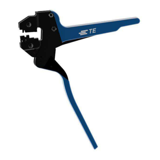
MATE-AX Hand Tool Assemblies
Figure 1: MATE-AX Hand Tool Assemblies
2
1
Inner Ferrule Tool
2
Center Contact Tool
3
Outer Contact Tool
Table 1: MATE-AX hand tool kits
Cable
RTK031
RG174 with foil
RG174 without foil
RTK031
RG174
RTK031
RG174
PRODUCT INFORMATION 1-800-522-6752
408-35051
3
Terminal
part numbers
2298126-1
2298509-1
2298121-1 (Socket)
2298125-1 (Pin)
2298496-1 (Socket)
2298508-1 (Pin)
2298116-1 (Socket)
2298123-1 (Pin)
2298494-1 (Socket)
2298506-1 (Pin)
This controlled document is subject to change.
For latest revision and Regional Customer Service,
visit our website at www.te.com.
Instruction Sheet
Rev A
24 JUN 2021
Strip length
Refer to TE
Specification
114-94413
N/A
1 of 11
Advertisement

Related Manuals for TE Connectivity MATE-AX 2335290-1


Summary of Contents for TE Connectivity MATE-AX 2335290-1
- Page 1 1 of 11 For latest revision and Regional Customer Service, All Rights Reserved. visit our website at www.te.com. TE Connectivity, TE connectivity (logo), and TE (logo) are trademarks. Other logos, product, and/or company names may be trademarks of their respective owners.
- Page 2 408-35051 1. INTRODUCTION MATE-AX Hand Tool Assemblies are the tools shown in Figure 1. Each tool consists of the SDE-SA Frame Assembly 9-1478240-0 (instruction sheet 408-8851) and a die assembly. These tools are used to crimp the terminal part numbers listed in Table 1. NOTE Dimensions in this instruction sheet are in millimeters with [inches in brackets].
- Page 3 408-35051 3. INSTALLING AND REMOVING THE DIE SET AND LOCATOR ASSEMBLY 1. Open the tool handles and remove the two die retaining screws from the tool jaws. 2. Place the wire anvil and insulation anvil so that their chamfered sides and the marked surfaces face outward when mounted in the moving jaw of the tool frame.
- Page 4 408-35051 4. CRIMPING 4.1. Inner ferrule tools NOTE The tool is provided with a crimp adjustment feature. Initially, the crimp height should be verified as specified in Figure 9. Refer to Section 5, INSPECTING THE CRIMP HEIGHT, and Section 6, ADJUSTING THE RATCHET, to verify crimp height before using the tool to crimp contacts and wire sizes.
- Page 5 408-35051 6. Position the stripped cable (see TE Specification 114-94413 Section 5.1 Step 1 for cable preparation) in the floating shear and seat the face of the stripped jacket against the locating surface in the floating shear (Figure 4). Figure 4: Positioning the cable (upper tooling removed for clarity) Stripped portion of cable Floating shear locating surface 7.
- Page 6 408-35051 4.2. Center contact tools NOTE The tool is provided with a crimp adjustment feature. Initially, the crimp height should be verified as specified in Figure 9. Refer to Section 5, INSPECTING THE CRIMP HEIGHT, and Section 6, ADJUSTING THE RATCHET, to verify crimp height before using the tool to crimp contacts and wire sizes.
- Page 7 408-35051 4. While holding the cable in place, fully cycle the tool until the ratchet releases and allows the handles to fully open. CAUTION Make sure that both sides of the wire barrel are started evenly into the crimping section. Do not attempt to crimp an improperly positioned contact.
- Page 8 408-35051 4. Release the terminal lock (Figure 8) to fix the sub-assembly in place. Figure 8: Releasing the terminal lock 5. Fully cycle the tool until the ratchet releases and allows the handles to fully open. CAUTION Make sure that both sides of the wire barrel are started evenly into the crimping section. Do not attempt to crimp an improperly positioned contact.
- Page 9 Crimp height inspection is performed using a micrometer with a modified anvil, commonly referred to as a crimp-height comparator. TE Connectivity does not manufacture or market crimp height comparators. Detailed information on obtaining and using crimp-height comparators can be found in Instruction Sheet 408-7424.
-
Page 10: Maintenance And Inspection
408-35051 6. ADJUSTING THE RATCHET The ratchet is preset prior to shipment, but it is important to verify the crimp height using a micrometer or caliper. Use and wear can cause the tool to go out of adjustment. Inspect the crimp height and adjust the ratchet, if necessary, on a regular basis. -
Page 11: Replacement And Repair
Shop TE link at the top of the page. Call 800-522-6752. Write to: CUSTOMER SERVICE (038-035) TE CONNECTIVITY CORPORATION PO BOX 3608 HARRISBURG PA 17105-3608 For customer repair services, call 800-522-6752. 9. REVISION SUMMARY Revisions to this instruction sheet include:...
Need help?
Do you have a question about the MATE-AX 2335290-1 and is the answer not in the manual?
Questions and answers