
Subscribe to Our Youtube Channel
Related Manuals for OSS OSS-581 Gen5 Backlane


Summary of Contents for OSS OSS-581 Gen5 Backlane
- Page 1 OSS-581 Gen5 Backplane INSTALLATION GUIDE OSS-581 Gen5 Backplane www.onestopsystems.com...
-
Page 2: Table Of Contents
Windows ..........................24 How to Get More Help ..................... 27 12.1 Contacting Technical Support ....................... 27 12.2 Returning Merchandise ....................... 27 12.3 Third Party Hardware & Software Support Policy ................27 12.4 Online Support Resources ......................27 OSS-581 Gen5 BP... -
Page 3: Getting Started
Check and identify the standard supplied item. Inspect the backplane for physical defects and damages. • To achieve superior performance and reliability it is recommended to use a certified and compatible set of an OSS Gen5 adapter cards (aka: Host Interface Board) and cables. -
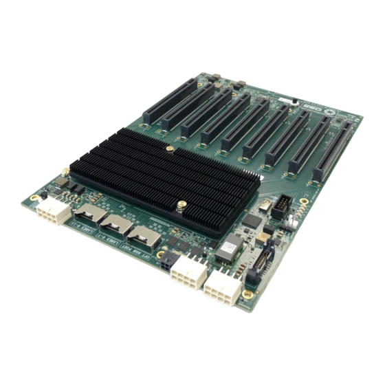
Page 4: Backplane Information
OFF - Not Linked / No Card present in the slot Blink 2Hz = Gen4 Link Aux Power LED Auxiliary Board power LED This is GREEN, denotes existence of Board is at fault / error auxiliary power +5VAUX OSS-581 Gen5 BP... -
Page 5: Board Leds
Link Status Slot 2 Green Link Status Slot 3 Green Link Status Slot 4 Green Link Status Slot 5 Green Link Status Slot 6 Green Link Status Slot 7 Green Link Status Slot 8 Green AUX Power Good OSS-581 Gen5 BP... -
Page 6: Slot Type
The board has a two-pin connector for placing a shunt / jumper that allows the backplane to be ON all the time when an ATX power supply is switched ON. See photos below for the location of the JP3 connector on the backplane. You can buy the shunt from any online hardware stores. OSS-581 Gen5 BP... -
Page 7: Block Diagram
One Stop Systems Block Diagram OSS-581 Gen5 BP... -
Page 8: Slot Number And Port Mapping
One Stop Systems Slot Number and Port Mapping Each slot on the OSS backplane is mapped to a PCIe port on the PCIe switch. Port mapping is hard-coded, it is fixed. No means of changing or modifying it. PCIE Slot Mapping... -
Page 9: Power Consumption
Max Power 400W (calculate ~330W but adding margin and factoring in efficiency of 3.3V power supplies) If PCIe cards are more than 25W, then the power goes up accordingly. Note: all OSS-581 power comes from +12V (except for ~5W max of +5Vsb). OSS-581 Gen5 BP... -
Page 10: Hardware Requirements
One Stop Systems Hardware Requirements OSS Gen 5 Target and Host Cards Gen 5 PCIe x8 Cable (qty: 2): QSFP-DD Cables Gen5 or Gen4 x16 PCIe slot (computer motherboard) ATX Power Supply: Minimum of 400 Watt Gen5 Target and Host Card QSFP-DD Cables ATX Power Supply with 24pin power cable and at least two available EPS power cable. -
Page 11: Pinouts
One Stop Systems Pinouts ATX 24pin connector pinout 12VInput Connector Pinout 5V Stand-by Connector Pinout OSS-581 Gen5 BP... -
Page 12: Setup / Installation
One Stop Systems Setup / Installation Install Jumper / Shunt on JP3 Plugin ARC Cables Connect the Arc cables to the Arf connectors onboard the backplane. Follow the diagram below for connecting the Arc Cables. OSS-581 Gen5 BP... -
Page 13: Set Backplane Dipswitches
Connect the first ARC cable to port LANES 8-15 Connect the 2 Arc cable to Port LANES 0-7 Set Backplane Dipswitches Configure the backplane SW Dipswitches. Set the switches using the settings shown from the photo below. OSS-581 Gen5 BP... -
Page 14: Connect Power Cables
Connect the other end of the cable to the ATX power supply 24pin power connector. From the ATX power supply, connect the 8pin power cable to the remaining 12v input power connector on the board. Below photo shows all the power cables attached to the backplane. OSS-581 Gen5 BP... -
Page 15: Install Adapter Card
Use the designated Target Slot / Upstream Slot on the backplane when installing the card. • See photo below for the correct default location of the Target slot (Upstream Slot). Plugin the target card in the upstream slot on the backplane. OSS-581 Gen5 BP... -
Page 16: Host Card Installation
One Stop Systems As shown below, the OSS target card is installed in Upstream slot 0. Host Card Installation The host card can only be installed in the computer motherboard’s PCIe slot. Install the Host card in an x16 Gen5 PCIe slot. -
Page 17: Cable Installation
Cable Installation Plugin the two cables to the target card. See photos below for the correct orientation of the cables when connecting to the card. Connect the other end of the cables to the host adapter card. OSS-581 Gen5 BP... -
Page 18: Powering Up The Unit
After powering UP the host computer, the Target SLOT LED on the backplane will illuminate as solid green as shown below. Check the board LEDS. A fully operational back plane will illuminate the following LEDs. • D4 &D5 • D19: AUX power, solid green. OSS-581 Gen5 BP... -
Page 19: Verify Adapter Card Leds
One Stop Systems Verify Adapter Card LEDs After powering ON the host computer, it will instantly power UP the target device. • A fully operational adapter cards will illuminate the following LEDs (on both Host and Target cards). OSS-581 Gen5 BP... -
Page 20: Mounting The Backplane
You want the screws properly tight enough to secure the backplane, but not so tight that can crack the board. • Once you’ve done the corners, put screws in the remaining holes. OSS-581 Gen5 BP... -
Page 21: Post Installation
11.1 Linux To check or verify if the OSS devices are detected, type or enter the command “lspci -vvv |grep c030”, see output below. • It will show 46 total number of c030 device IDs, combining both OSS_579 adapter cards and the OSS_581 board. - Page 22 This is the single OSS_579 host card displaying 13 of c030 device IDs. To check on the OSS-581 device hierarchy type or enter the command on a terminal window “lspci -vvtt”. The screenshot below shows the hierarchy (tree-like structure) of the OSS_581 backplane without PCIe cards in the slots.
- Page 23 One Stop Systems Photo below shows the hierarchy order of eight physical slots on the OSS_581 backplane populated with different PCIe cards. OSS-581 Gen5 BP...
-
Page 24: Windows
• An instance of PCI Express Upstream Switch Port will appear; select and expand the arrow signs. Four instances of PCI Express Downstream Switch Ports will show up. Select and expand all PCI Express Downstream Switch Ports. OSS-581 Gen5 BP... - Page 25 Continue to expand all arrow signs until everything is fully expanded. The screenshot below shows a fully expanded PCI Express Upstream and downstream Ports. • Displaying the OSS-581 + both OSS-579 cards are detected in Windows Device Manager. • There are no PCIe cards installed in the slots.
- Page 26 One Stop Systems The screenshot below shows the hierarchy of OSS_581 card slots populated with 8 different PCIe cards. • All 8 PCIe cards are detected in Windows Device Manager. OSS-581 Gen5 BP...
-
Page 27: How To Get More Help
We assess, certify, and support many third-party hardware and software products along with OSS hardware and are happy to integrate a fully supported system. Ask us about that service and we would be happy to help. If an OSS product is fully functional and a support issue is related to third-party hardware or software that did not ship from the OSS factory, the customer requesting support should reach out to the third-party vendor for assistance to fully troubleshoot the issue. - Page 28 One Stop Systems OSS-581 Gen5 BP...
Need help?
Do you have a question about the OSS-581 Gen5 Backlane and is the answer not in the manual?
Questions and answers