
Related Manuals for H3C PSR650C-12A


Summary of Contents for H3C PSR650C-12A
- Page 1 H3C PSR650C-12A & PSR650C-12D Power Modules User Manual New H3C Technologies Co., Ltd. http://www.h3c.com Document version: 6PW101-20220922...
- Page 2 All rights reserved No part of this manual may be reproduced or transmitted in any form or by any means without prior written consent of New H3C Technologies Co., Ltd. Trademarks Except for the trademarks of New H3C Technologies Co., Ltd., any trademarks that may be mentioned in this document are the property of their respective owners.
-
Page 3: Table Of Contents
Contents Contents ····························································· i Overview ···························································· 1 Front panel ··············································································· 1 Technical specifications ···························································· 2 LEDs························································································· 3 Installing and removing the power module ········· 5 Safety precautions ···································································· 5 Installing the power module ······················································ 5 Removing the power module ···················································· 7 Connecting the power cord ·······················································... -
Page 4: Overview
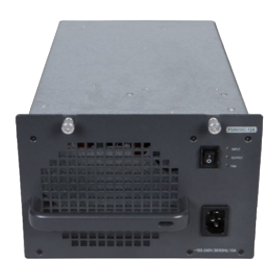
Overview The PSR650C-12A is an AC-input, DC-output power module, and the PSR650C-12D is a DC-input and DC-output power module. They each can provide a maximum output of 650 W. The power modules support 1+1 redundancy and load sharing and are removable. They also provide output overcurrent, output overvoltage, output short circuit, and overtemperature protections. -
Page 5: Technical Specifications
(6) DC input positive terminal (+) (7) DC input negative terminal (–) (8) Grounding point (9) Handle Technical specifications Table 1 Technical specifications Item PSR650C-12A PSR650C-12D Rated input 100 to 240 VAC @ –48 to –60 VDC voltage 50 or 60 Hz... -
Page 6: Leds
(14°F to 131°F) (14°F to 131°F) Operating 5% RH to 95% RH 5% RH to 95% RH humidity LEDs The PSR650C-12A/PSR650C-12D power module provides three red-green status LEDs. Table 2 LED description Status Description Green The power is being input correctly. - Page 7 Status Description Green The power is being output correctly. A power output problem has occurred because one of the following conditions exists: • The power module generates an alarm and enters protection state because of input undervoltage, output short circuit, output overcurrent, output overvoltage, OUTPUT overtemperature, or fan failure.
-
Page 8: Installing And Removing The Power Module
• Do not open the power module. When the internal circuits or components of the power module fail, contact H3C Support. Installing the power module WARNING! Turn off the power switch before installing the power module. - Page 9 To avoid bodily injury and device damage, follow the procedure in Figure 3 to install a power module. Figure 3 Power module installation procedure Remove the filler panel Install the power module Connect the power cord Turn on the circuit breaker To install the power module: Wear an ESD wrist strap, and make sure the strap makes good...
-
Page 10: Removing The Power Module
power module is fully seated in the slot. Then fasten the captive screws. If you encounter a hard resistance while inserting the power module or fastening a captive screw, pull out the power module, reorient it, and then insert it again. Figure 4 Installing the power module Removing the power module To avoid device damage and bodily injury, follow the procedure in... - Page 11 Figure 5 Power module removal procedure Turn off the circuit breaker Remove the power cord Remove the power module Install the filler panel To remove the power module: Turn off the circuit breaker of the power cord. Prepare an antistatic mat to place the removed power module. Wear an ESD wrist strap, and make sure the strap makes good skin contact and is reliably grounded.
-
Page 12: Connecting The Power Cord
If you are not to install a new power module, install a filler panel over the empty power module slot. Figure 6 Removing the power module Connecting the power cord Connecting the AC power cord WARNING! • Make sure each power module has a separate circuit breaker. - Page 13 To connect the AC power cord: Unpack the power cord, and verify that the power cord model is correct. Connect the power cord to the power receptacle of the power module. Make sure the power cord is securely inserted into the power receptacle.
-
Page 14: Connecting The Dc Power Cord
Connecting the DC power cord WARNING! • Make sure each power module has a separate circuit breaker. • Turn off the circuit breaker before connecting the power cord. To connect the DC power cord: Remove the protection cover from the power module. Remove the screw on the wiring terminal with a Phillips screwdriver. - Page 15 Figure 8 Connecting the DC power cord NOTE: The power cord color code scheme in Figure 8 is for illustration only. The cord delivered for your country or region might use a different color scheme. When you connect a power cord, always identify the polarity symbol on its wires.
Need help?
Do you have a question about the PSR650C-12A and is the answer not in the manual?
Questions and answers