
Related Manuals for H3C PSR650-A


Summary of Contents for H3C PSR650-A
- Page 1 H3C PSR650-A & PSR650-D Power Module User Manual New H3C Technologies Co., Ltd. http://www.h3c.com Document version: T2-08010P-20180115-C-1.03...
- Page 2 Copyright © 2007-2018, New H3C Technologies Co., Ltd. and its licensors All rights reserved No part of this manual may be reproduced or transmitted in any form or by any means without prior written consent of New H3C Technologies Co., Ltd. Trademarks H3C,...
- Page 3 Documentation feedback You can e-mail your comments about product documentation to info@h3c.com. We appreciate your comments...
-
Page 4: Table Of Contents
Contents Introduction ··············································· 1 Schematic Views ···························································· 2 Specifications ································································· 3 Status LED ···································································· 3 Power Module Installation and Removal ·········· 5 Installing and Removing a Power Module ···························· 5 Installing a Power Module ············································ 6 ... -
Page 5: Introduction
Introduction The PSR650-A is a built-in power module with AC input and DC output while the PSR650-D is a built-in power module with DC input and DC output. These two power module models can transfer the input voltage into 12 V or 3.3 V needed by the device. -
Page 6: Schematic Views
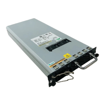
Schematic Views Figure 1 Schematic view of the PSR650-A (1) (2) (1) Bail latch (2) AC power socket (3) Power switch (4) Status LED (5) Power module handle (6) Captive screws Figure 2 Schematic view of the PSR650-D (1) Grounding point (2) Positive (+) terminal of DC input (3) Negative (–) terminal of DC input... -
Page 7: Specifications
13.78 in.) PSR650-A: 2.5 kg (5.51 lb) Weight PSR650-D: 2.3 kg (5.07 lb) Operating 0~55°C Environment temperature temperature Storage requirement -40~70°C temperature Status LED The PSR650-A and PSR650-D have only one status LED. Table 3describes its colors and working status. - Page 8 Table 3 Description of LEDs on the PSR650-A and PSR650-D Color/status Meaning Possible causes The power Green module is — operational. Power alarm (input under-voltage, output short circuit, output over-current, The power output over-voltage, or overheat module is occurred to the power module, faulty.
-
Page 9: Power Module Installation And Removal
Installing and Removing a Power Module This section describes how to install and remove a PSR650-A power module. You can install and remove a PSR650-D power module in a similar way. You need to prepare the tools that you need to use to install or remove power modules. -
Page 10: Installing A Power Module
Figure 5 Install/remove a PSR650-A power module Installing a Power Module Wear an ESD-preventive wrist strap and take a new power module out of its package. Check that the input mode of the power module is correct. Grasp the handle of the module with one hand and hold the module bottom with the other. -
Page 11: Removing A Power Module
CAUTION: If the captive screws cannot be tightened, check whether the power module is properly installed. Removing a Power Module Remove a power module in the opposite way you install it: Wear an ESD-preventive wrist strap and loosen the captive screws on the power module. -
Page 12: Connecting The Ac Power Cable
Connecting the AC Power Cable Figure 6 Connect the AC power cable (I) Figure 7 Connect the AC power cable (II) Plug one end of the power cable shipped with the device into the power socket and use the bail latch to lock the power cable. Plug the other end into the AC power socket strip of the AC mains. -
Page 13: Connecting The Dc Power Cables
Connecting the DC Power Cables Figure 8 Connect the DC power cables CAUTION: • Turn off all power supplies to the device before connecting the DC power cables. • The power cord color code scheme in Figure 8 is for illustration only.
Need help?
Do you have a question about the PSR650-A and is the answer not in the manual?
Questions and answers