Advertisement
Quick Links
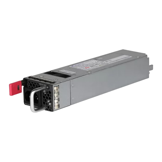
H3C PSR360-56A Power Module
User Manual-6PW103
Power module overview
PSR360-56A is an AC-input and DC-output power module. It provides
a maximum output of 360 W and delivers the following features:
Table 1 Features
Feature
Protection
Redundancy
Hot
swapping
Technical specifications
Table 2 Technical specifications
Item
Rated input voltage
Maximum input voltage
Description
Protection against over-current input, under-voltage
input, over-voltage output, output current limiting,
output short circuit, and over-temperature.
When you install two power modules on a device,
the two power modules support 1+1 redundancy
and load sharing.
You can install or remove a power module when
the switch is operating.
Specifications
100 VAC to 240 VAC @ 50 Hz or 60 Hz
90 VAC to 264 VAC @ 47 Hz to 63 Hz
1
BOM: 3101A0GN
Advertisement

Subscribe to Our Youtube Channel
Related Manuals for H3C PSR360-56A


Summary of Contents for H3C PSR360-56A
- Page 1 H3C PSR360-56A Power Module User Manual-6PW103 BOM: 3101A0GN Power module overview PSR360-56A is an AC-input and DC-output power module. It provides a maximum output of 360 W and delivers the following features: Table 1 Features Feature Description Protection against over-current input, under-voltage...
- Page 2 Item Specifications Maximum input current Output voltage –56 V Output current 6.45 A Maximum output 360 W power Dimensions (H × W × 40.1 × 82.6 × 259.5 mm (1.58 × 3.25 × 10.22 in) Operating temperature –10°C to +55°C (14°F to 131°F) Relative humidity 5% to 95% Appearance...
-
Page 3: Installing And Removing The Power Module
(1) Input status LED (AC OK) (2) AC-input power receptacle (3) Latch (4) Handle (5) Output status LED (DC OK) LEDs The power module has two status LEDs on its front panel. Table 3 LED description Status Description Steady green The power input is normal. - Page 4 • To avoid power module damage, do not open the power module. When the internal circuits or components of the power module fail, contact H3C Support. Tools Prepare an ESD wrist strap and a flat-blade screwdriver yourself. Installing and removing the power module...
- Page 5 Put your finger into the hole in the filler panel and pull the filler panel out along the guide rails. Insert a flat-blade screwdriver through the handle on the filler panel and pull the filler panel out along the guide rails. Figure 3 Removing a filler panel Insert the power module into the slot, as shown in Figure...
- Page 6 Figure 4 Installing the power module...
-
Page 7: Removing The Power Module
Figure 5 Securing the AC power cord Connect the other end of the AC power cord to the AC power source, and turn on the circuit breaker. Examine the AC OK LED on the power module. If the LED is steady green, the power cord is connected correctly. - Page 8 If you are not to insert a power module into the empty slot, insert the filler panel into the slot to prevent dust from entering the chassis. Figure 7 Removing the power module Copyright © 2013-2017 New H3C Technologies Co., Ltd.
Need help?
Do you have a question about the PSR360-56A and is the answer not in the manual?
Questions and answers