Table of Contents
Advertisement
Quick Links
SECURITY DOOR CONTROLS ■ WWW.SDCSECURITY.COM
[t] 800.413.8783 ■ 805.494.0622 ■ E-mail: service@sdcsecurity.com ■ 801 Avenida Acaso, Camarillo, CA 93012 ■ PO Box 3670, Camarillo, CA 93011
A. Door Preparation:
1. Measure desired height from finished floor, mark a horizontal line on door and door edge.
2. Align template on edge of door with applicable horizontal at height line. Check the chart for drilling trim
holes on template and mark only holes for lock function being installed.
Height
line
3. Mortise door edge according to measurements on
installation template and drill proper holes for trim.
4. Recess for face plate, the dimension is:
L 8-1/32" x W 1-5/16" x D 7/32".
7/32"
Note:
Rose door prep shown as example.
Escutcheon door prep would differ.
P:\INST INSTRUCTIONS\ELECTRIFIED LOCKSETS\INST-Z7835-E
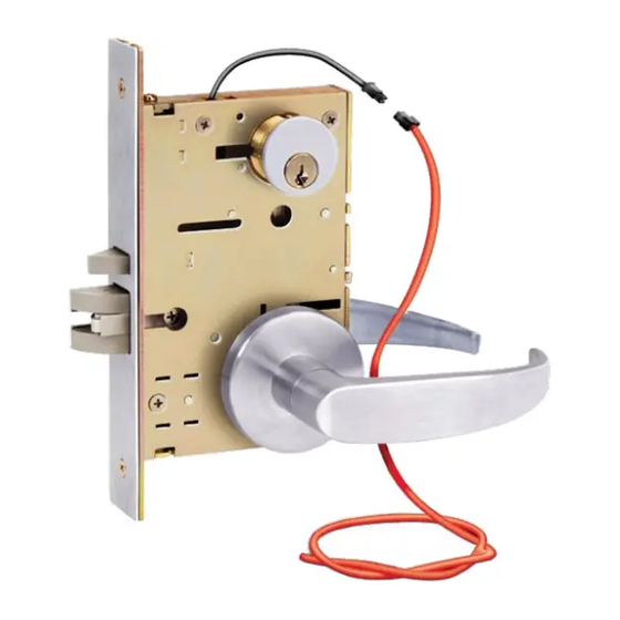
INSTALLATION INSTRUCTIONS
Z7835 PRO SERIES
12VDC LOCKED OUTSIDE / INSIDE
MORTISE LOCKSET
C L of lever
of door edge
C L
Wire Raceway suggested for wood doors.
Optional:
SDC Door Core Drill Guide Kit
P/N: 7000-DGK
REV G
09-22
Page 1
Installation Template
C L
of cylinder
C L
of lockcase
C L
of lever
Vertical centerline
Any suggestions or comments to this instruction or
product are welcome. Please contact us through
our website or email engineer@sdcsecurity.com
Advertisement
Table of Contents

Subscribe to Our Youtube Channel
Related Manuals for SDC PRO Series


Summary of Contents for SDC PRO Series
- Page 1 Wire Raceway suggested for wood doors. installation template and drill proper holes for trim. Optional: 4. Recess for face plate, the dimension is: SDC Door Core Drill Guide Kit L 8-1/32" x W 1-5/16" x D 7/32". P/N: 7000-DGK 7/32"...
- Page 2 SECURITY DOOR CONTROLS ■ WWW.SDCSECURITY.COM [t] 800.413.8783 ■ 805.494.0622 ■ E-mail: service@sdcsecurity.com ■ 801 Avenida Acaso, Camarillo, CA 93012 ■ PO Box 3670, Camarillo, CA 93011 B. Strike Installation: Align strike template on jamb. Be sure to keep 3/8" distance between lock centerline and strike centerline.
- Page 3 SECURITY DOOR CONTROLS ■ WWW.SDCSECURITY.COM [t] 800.413.8783 ■ 805.494.0622 ■ E-mail: service@sdcsecurity.com ■ 801 Avenida Acaso, Camarillo, CA 93012 ■ PO Box 3670, Camarillo, CA 93011 C. Install Lockcase (Continued) 2. Connect wires as shown on the lock cover diagram (or refer to page 6 of instructions). 3.
- Page 4 SECURITY DOOR CONTROLS ■ WWW.SDCSECURITY.COM [t] 800.413.8783 ■ 805.494.0622 ■ E-mail: service@sdcsecurity.com ■ 801 Avenida Acaso, Camarillo, CA 93012 ■ PO Box 3670, Camarillo, CA 93011 D. Install for 07 Lever Trim 1. Install the Outside Lever Assembly first. 2. Insert Spindle into the outside side of mortise lockset. 3.
- Page 5 SECURITY DOOR CONTROLS ■ WWW.SDCSECURITY.COM [t] 800.413.8783 ■ 805.494.0622 ■ E-mail: service@sdcsecurity.com ■ 801 Avenida Acaso, Camarillo, CA 93012 ■ PO Box 3670, Camarillo, CA 93011 D. Install for Escutcheon Lever Trim 1. Install the Outside Lever first. 2. Place Spindle Spring over outside Spindle, then insert Spindle into the outside sides of lockset. 3.
- Page 6 SECURITY DOOR CONTROLS ■ WWW.SDCSECURITY.COM [t] 800.413.8783 ■ 805.494.0622 ■ E-mail: service@sdcsecurity.com ■ 801 Avenida Acaso, Camarillo, CA 93012 ■ PO Box 3670, Camarillo, CA 93011 INSTALLATION WIRE DIAGRAM Model Z7835 Series 12VDC ONLY TYPICAL WIRING (NO OPTIONS) 12VDC 4 PIN CONNECTOR OUTSIDE SOLENOID Fail-Secure...
Need help?
Do you have a question about the PRO Series and is the answer not in the manual?
Questions and answers