Advertisement
Quick Links
SECURITY DOOR CONTROLS ■ WWW.SDCSECURITY.COM
[t] 800.413.8783 ■ 805.494.0622 ■ E-mail: service@sdcsecurity.com ■ 801 Avenida Acaso, Camarillo, CA 93012 ■ PO Box 3670, Camarillo, CA 93011
TOOLS REQUIRED FOR NEW INSTALLATION:
1 philips head screwdriver
1 1" (25.4mm) drill bit
1 chisel
INSIDE
LEVER
LEVER
CATCH
TOOL
INSIDE MOUNTING
PLATE
LATCH
1. MARK DOOR
a. Mark centerline on door face and door edge
b. Select backset 2-3/8" or 2-3/4" and mark hole
NOTE: BACKSET ON DOOR FACE MUST BE
c
a
c. Mark two holes for screw post.
b
P:\INST INSTRUCTIONS\ELECTRIFIED LOCKSET\INST-Z7200
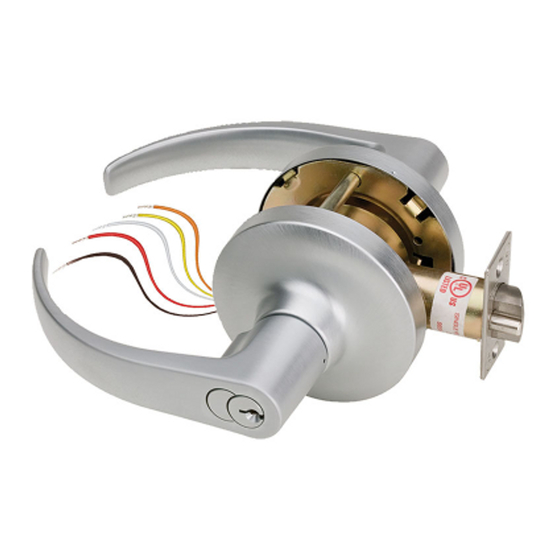
INSTALLATION INSTRUCTIONS
CYLINDRICAL LOCK
FOR USE ON DOORS 1-3/8" ~ 2" (35mm ~ 51mm) THICK
1 2-1/8" (54MM) hole saw
1 5/16" (8mm) drill bit
1 file
INSIDE
ROSE w/LINER
LOCK BODY
ASSEMBLY
OUTSIDE
LEVER
(usually 38" from finished floor)
center on door face
THE SAME AS BACKSET OF YOUR
LOCK.
Fold template for High or
Low Bevel positioning
(reference template)
Rev M
Z7200
OPTIONAL:
DOOR CORE DRILLING GUIDE #7000-DG &
CORING DRILL BIT #7000-DB
OUTSIDE
MOUNTING
PLATE
OUTSIDE
ROSE
2. DRILL HOLES
5/16" (8mm) hole for
screw post
2-1/8" (54mm)
Hole for lockset
08-21
Page 1
1" or 31/32"
(24.6mm or 25.4mm)
hole for latch
Any suggestions or comments to this instruction or
product are welcome. Please contact us through
our website or email engineer@sdcsecurity.com
Advertisement

Subscribe to Our Youtube Channel
Related Manuals for SDC Z7200


Summary of Contents for SDC Z7200
- Page 1 Fold template for High or Low Bevel positioning (reference template) 2-1/8” (54mm) Hole for lockset Any suggestions or comments to this instruction or product are welcome. Please contact us through P:\INST INSTRUCTIONS\ELECTRIFIED LOCKSET\INST-Z7200 Rev M 08-21 Page 1 our website or email engineer@sdcsecurity.com...
- Page 2 PLATE OUTSIDE LEVER ASSEMBLY LEVER CATCH TOOL Use lever catch tool to depress lever catch, visible under hole of inside lever shank and slide off inside lever, rose liner and mounting plate. P:\INST INSTRUCTIONS\ELECTRIFIED LOCKSET\INST-Z7200 Rev M 08-21 Page 2...
- Page 3 Confirm lever is secured. INSIDE MOUNTING PLATE INSIDE ROSE b. Press inside rose onto mounting plate and tighten screws securely. INSIDE LEVER ROSE LINER INSIDE ROSE MOUNTING SCREWS P:\INST INSTRUCTIONS\ELECTRIFIED LOCKSET\INST-Z7200 Rev M 08-21 Page 3...
- Page 4 3A @ 30VDC 200mA @ 30VAC (RESISTIVE) COM = WHT/RED COM = GREY *Both options cant be used LATCH STATUS N/C = ORG/RED N/C = YELLOW simultaneously. N/O = YEL/RED N/O = ORANGE P:\INST INSTRUCTIONS\ELECTRIFIED LOCKSET\INST-Z7200 Rev M 08-21 Page 4...
Need help?
Do you have a question about the Z7200 and is the answer not in the manual?
Questions and answers