Table of Contents
Advertisement
Quick Links
801 Avenida Acaso, Camarillo, Ca. 93012 • (805) 494-0622 •
www.sdcsecurity.com • E-mail: service@sdcsecurity.com
2-1/4"
1-1/2"
3/4"
2"
Quick Mount
Interlocking
Mounting Assembly
Mounting Screws
Electrical Instructions:
Use properly fused U. L. Listed Power Supply
Do not install a diode in parallel with any magnetic lock. A diode
will cause a delay when releasing the door and residual magnetism
to occur.
Access controls and/or release contacts must be located in series
with the positive (+) power lead of the EmLock.
Any low voltage condition will cause erratic operation of the
optional board sensor.
Although SDC recommends the use of a Regulated DC power supply,
a significant voltage drop will occur when using a full wave bridge rectifier.
Installation Location – Indoor Dry
P:\INSTALLATION INST\Electromagnetic Locks\INST-352.vsd
INSTALLATION INSTRUCTIONS
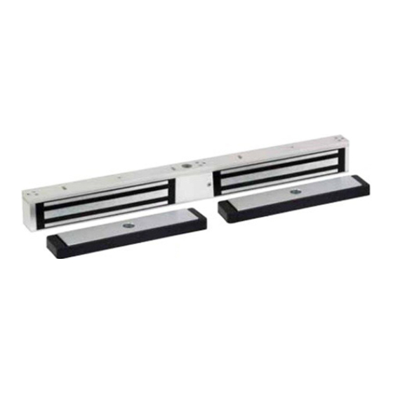
352 NARROW LINE EMLOCK
10"
Interlocking
Mounting Plate
Armature
SIGNALING
use only
C
LISTED
REV -.3
25"
Frame
Electrical Specifications:
Dual Voltage
Power Consumption
DS Door Status Sensor SPDT, 250mA@24VDC
LS Lock Status Sensor SPDT, 1A@24VDC
US
PATENT NO. 5,376.910
08-18
Page 1
Outswing
12 or 24VDC
1120mA@12VDC
618mA@24VDC
Supplied Mounting Hardware
Any suggestions or comments to this instruction or
product are welcome. Please contact us through
our website or email engineer@sdcsecurity.com
Advertisement
Table of Contents

Subscribe to Our Youtube Channel
Related Manuals for SDC 352 Narrow Line EMLock


Summary of Contents for SDC 352 Narrow Line EMLock
-
Page 1: Installation Instructions
Supplied Mounting Hardware Any low voltage condition will cause erratic operation of the optional board sensor. Although SDC recommends the use of a Regulated DC power supply, a significant voltage drop will occur when using a full wave bridge rectifier. SIGNALING Installation Location –... - Page 2 1. Fold template as indicated on dotted line. For double doors center template against the doors and header. 2. Mark and drill holes as indicated by the template. STEPS 1 & 2 3. Mount armatures to doors. REINFORCEMENT STEEL WASHER 2X 1-3/4“...
- Page 3 5. Holding the magnet housing at each end, engage the entire length of the interlock detail, by pushing towards the door. Tap with a soft hammer to ensure proper alignment and engagement. CAUTION: The lock body must be held in place until secured with mounting screws. Secure socket head screws provided inside the housing at each end.
Need help?
Do you have a question about the 352 Narrow Line EMLock and is the answer not in the manual?
Questions and answers