Advertisement
Quick Links
801 Avenida Acaso, Camarillo, Ca. 93012 • (805) 494-0622 •
www.sdcsecurity.com • E-mail: service@sdcsecurity.com
1. Determine the appropriate mounting configuration for your application (Header mount or Top-jamb or Side-jamb
mount.
FRAME HEADER
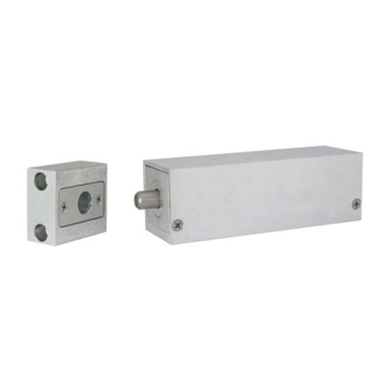
LOCK
STRIKE
DOOR
END VIEW
Header Mount
Outswing Door
2. Determine the handing for your application.
Header Mount
LOCK
LHR
3. Remove the lock housing cover. Based on the mounting information determined on steps 1 & 2 above, adjust
the Auto Relock Switch (ARS) in the bolt chamber bracket as described below.
Mounting Configuration
Header Mounted ‐ LHR
Header Mounted ‐ RHR
Top Jamb or Side Jamb ‐ Swing (LH or RH)
Top Jamb ‐ Sliding to Left*
Top Jamb ‐ Sliding to Right*
*Tob Jamb Sliding Door requires a positive stop
3a. Remove the ARS insert and install the ARS switch as shown. Replace the plastic insert.
Perpendicular to
Mounting Plate
P:\INSTALLATION INST\Electric Bolt Locks\TEMP-180-280\INST-180_280.vsd REV E 08-17 Page 1
INSTALLATION INSTRUCTIONS/TEMPLATE
180/280 SERIES ELECTRIC LOCKS
LOCK
FRAME HEADER
OR SIDE JAMB
STRIKE
DOOR
Top or Side Jamb
Inswing or Sliding Door
LOCK
RHR
Strike
Block
Auto‐Relock Switch Orientation
Perpendicular to the mounting plate
Perpendicular to the mounting plate
Perpendicular to the mounting plate
Parallel to the mounting plate
Parallel to the mounting plate
Header
Mount
Strike
Block
Lock
Top-jamb
LH
EXTERIOR
ARS Cover
Mounting
Parallel to
Mounting Plate
Top-
Jamb
Side-
Jamb
Strike
Block
RH
Insert
Plate
Any suggestions or comments to this instruction or
product are welcome. Please contact us through
our website or email engineer@sdcsecurity.com
Lock
Side-jamb
LOCK
Bolt
Chamber
Bracket
Advertisement

Related Manuals for SDC TEMPLATE 180 SERIES


Summary of Contents for SDC TEMPLATE 180 SERIES
- Page 1 801 Avenida Acaso, Camarillo, Ca. 93012 • (805) 494-0622 • www.sdcsecurity.com • E-mail: service@sdcsecurity.com INSTALLATION INSTRUCTIONS/TEMPLATE 180/280 SERIES ELECTRIC LOCKS 1. Determine the appropriate mounting configuration for your application (Header mount or Top-jamb or Side-jamb mount. LOCK Top- FRAME HEADER FRAME HEADER Jamb OR SIDE JAMB...
- Page 2 4. Configure the strike block assembly 4a. For Header-mounted, RHR (Choose 4a, 4b, or 4c): This end towards the ARS magnet door Strike Block Strike hole towards magnet Block Shim Strike Insert (use as w/ screws needed) 4c. For Top Jamb (swing or slide) or Side Jamb 4b.
- Page 3 LOCK WIRING NOTE: The SDC PR-1000 Power Regulator module is included with the 180/280 bolt lock, and is required for optimal solenoid lifespan. Installing the PR-1000 reduces the power consumption of the bolt locks after activation of the lock, allowing for a heat reduction to the bolt lock.
- Page 4 STOP STOP STOP BLOCK BLOCK BLOCK STRIKE STRIKE STRIKE P:\INSTALLATION INST\Electric Bolt Locks\TEMP-180-280\INST-180_280.vsd REV E 08-17 Page 4...
Need help?
Do you have a question about the TEMPLATE 180 SERIES and is the answer not in the manual?
Questions and answers