Table of Contents

Related Manuals for Avalue Technology EMX-CDT


Summary of Contents for Avalue Technology EMX-CDT
- Page 1 EMX-CDT Intel® Atom™ Cedar Trail Mini ITX Motherboard With Intel® D2550 Processor + NM10 Chipset User’s Manual Ed – 18 January 2013 Copyright Notice Copyright 2013 Avalue Technology Inc., ALL RIGHTS RESERVED. Part No. E2047XCDT01R...
-
Page 2: Table Of Contents
2.3.16 JCOM1-6 (9th Pin definition) ..............21 3.BIOS Setup ........................22 Introduction ....................23 Starting Setup ....................23 Using Setup ....................24 Getting Help ....................25 In Case of Problems ..................25 BIOS setup ....................26 2 EMX-CDT User’s Manual... - Page 3 Install Audio Driver (For Realtek ALC661 HD Audio) ........42 Install Chipset Driver (For Intergated Cedar Trail) ........43 Install VGA Driver ..................44 Install LAN Driver (For Realtek 8111E Gigabit Ethernet) ......45 5. Mechanical Drawing ....................46 EMX-CDT User’s Manual 3...
-
Page 4: Getting Started
Rear I/O bracket X 1 Quick Installation Guide X 1 Driver/Utility CD X 1 Serial ATA Signal Cable X 1 COM Cable X 1 Motherboard X 1 4 EMX-CDT User’s Manual... -
Page 5: Document Amendment History
EMX-CDT User’s Manual 1.3 Document Amendment History Revision Date Comment June 2012 Avalue Initial Release January Avalue Update Drivers Installation 2013 EMX-CDT User’s Manual 5... -
Page 6: Manual Objectives
We strongly recommend that you study this manual carefully before attempting to set up EMX-CDT series or change the standard configurations. Whilst all the necessary information is available in this manual we would recommend that unless you are confident, you contact your supplier for guidance. -
Page 7: Specifications
*Mini PCI-e and m-SATA SSD switch through Jumper 1x PCIE x1 Serial port x 6 internal RS-232 ports with 5V/12V power 2x SATAII Connector(3Gb/s) 1 x 10 pin-headers for VGA output port (The I/O VGA DB15 connector & EMX-CDT User’s Manual 7... - Page 8 Operating Temp. 0 ~ 60°C (32 ~ 140°F) Storge Temp -40 ~ 75°C (-40 ~ 167°F) Operating 0 ~ 90% Relative Humidity, Non-condensing Humidity Size (L x W) 6.69” x 6.6” (170mm x 170mm) Weight 1.058lbs (0.48kg) 8 EMX-CDT User’s Manual...
-
Page 9: Architecture Overview-Block Diagram
EMX-CDT User’s Manual 1.6 Architecture Overview—Block Diagram The following block diagram shows the architecture and main components of EMX-CDT. EMX-CDT User’s Manual 9... -
Page 10: Hardware Configuration
EMX-CDT User’s Manual 2. Hardware Configuration 10 EMX-CDT User’s Manual... -
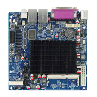
Page 11: Product Overview
EMX-CDT User’s Manual 2.1 Product Overview 2.1.1 Main board layout 2.1.2 Connecting Rear Panel I/O Devices EMX-CDT User’s Manual 11... -
Page 12: Installation Procedure
6. Enter the BIOS setup by pressing the delete key during boot up. Use the "Save & Exit \ Restore Defaults" feature. 7. If TFT panel display is to be utilized, make sure the panel voltage is correctly set before connecting the display cable and turning on the power. 12 EMX-CDT User’s Manual... -
Page 13: Setting Jumpers & Connectors
Pin No. Definition 3.3V 1-2, Set JLVDS1 Pin1,2,5,6 VDDSAFE as 5V 2-3, Set JLVDS1 Pin1,2,5,6 VDDSAFE as 3.3V 2.3.2 20PIN ATXPWR Pin No. Definition Pin No. Definition +3.3V +3.3V PWR OK +5VSB +12V +3.3V -12V PS-ON EMX-CDT User’s Manual 13... -
Page 14: Jlvds1
EMX-CDT User’s Manual 2.3.3 JLVDS1 Pin No. Definition Pin No. Definition Pin No. Definition Pin No. Definition VDDSAFE VDDSAFE LVDS0_P2 VDDSAFE VDDSAFE LVDS0_CLKN LVDS0_N0 LVDS0_CLKP LVDS0_P0 LVDS_DDCPCLK LVDS_DDCPDATA LVDS0_N1 LVDS0_P1 LVDS0_N3 LVDS0_P3 LVDS0_N2 LVDS_VCON 14 EMX-CDT User’s Manual... -
Page 15: Ju1/ Ju2
When you want to use Wifi on MINIPCIE1 slot, please set up JP1-JP4 as 1-2. When you want to use M-SATA on MINIPCIE1 slot, please set up JP1-JP4 as 2-3. When you use SATA2 connect, please set up JP1-JP4 as 3-4. EMX-CDT User’s Manual 15... -
Page 16: Jir1/ Jir2
For COM2, please set up JIR1/ JIR2 as 1-2. For IR, please set up JIR1/ JIR2 as 2-3. 2.3.7 FPANEL1 Pin No. Definition Pin No. Definition 5VSB +HD_LED +P_LED -HD_LED -P_LED PS_ON +SPEAK -PS_ON RESET -RESET -SPEAK +SLEEP_LED -SLEEP_LED 16 EMX-CDT User’s Manual... -
Page 17: Jvga
(The I/O VGA DB15 connector & 2 x 5 pin-headers can’t use in the same time) Pin No. Definition Pin No. Definition HSYNC VSYNC DDC_DATA DDC_CLK 2.3.9 GPIO Pin No. Definition Pin No. Definition +12V GPIO GPIO GPIO GPIO GPIO GPIO GPIO GPIO EMX-CDT User’s Manual 17... -
Page 18: Jinvert1
EMX-CDT User’s Manual 2.3.10 JINVERT1 Pin No. Definition Pin No. Definition BLEN 2.3.11 IRDA Only for specially used (Can’t send data) Pin No. Definition Pin No. Definition IRRX IRTX 18 EMX-CDT User’s Manual... -
Page 19: Fusb1/Fusb2
Data 0+ Data 1+ NC(CUT) When JU1/JU2 jumpers are set to 2-3, FUSB2 (USB7) will be disabled. (Please refer to P.15 2.3.4 for more information.) 2.3.13 F_AUDIO Pin No. Definition FRONT_MIC VREF_OUT FRONT_OUT_R AUD_RET_R NC(CUT) FRONT_OUT_L AUD_RET_L EMX-CDT User’s Manual 19... -
Page 20: Jspdif1
EMX-CDT User’s Manual 2.3.14 JSPDIF1 Pin No. Definition 2.3.15 JCOM1-6 Pin No. Definition Pin No. Definition NC(CUT) 20 EMX-CDT User’s Manual... -
Page 21: Jcom1-6 (9Th Pin Definition)
EMX-CDT User’s Manual 2.3.16 JCOM1-6 (9th Pin definition) COM1 to COM6 9th Pin definition Pin No. Definition JC11/12/13 CLOSE JC14/15/16 OPEN USE JC1-JC6 JC1/2/3 JC4/5/6 +12V EMX-CDT User’s Manual 21... -
Page 22: Bios Setup
EMX-CDT User’s Manual 3.BIOS Setup 22 EMX-CDT User’s Manual... -
Page 23: Introduction
If you do not press the keys at the correct time and the system does not boot, an error message will be displayed and you will again be asked to. Press DEL to enter SETUP EMX-CDT User’s Manual 23... -
Page 24: Using Setup
Note: Some of the navigation keys differ from one screen to another. To Display a Sub Menu Use the arrow keys to move the cursor to the sub menu you want. Then press <Enter>. A “” pointer marks all sub menus. 24 EMX-CDT User’s Manual... -
Page 25: Getting Help
Award and your systems manufacturer to provide the absolute maximum performance and reliability. Even a seemingly small change to the chipset setup has the potential for causing you to use the override. EMX-CDT User’s Manual 25... -
Page 26: Bios Setup
Note: BIOS setup screens shown in this chapter are for reference only, and may not exactly match what you see on your screen. Visit the Avalue website (www.avalue.com.tw) to download the latest product and BIOS information. 26 EMX-CDT User’s Manual... -
Page 27: Advanced Bios Settings
Onboard Lan BootROM Control Enabled Network Devices. Disabled, Enable or disable Boot Option for Legacy Launch Storage OpROM Enabled[Default] Mass storage devices With Option ROM. 3.6.2.1 ACPI Settings You can use this item to set up ACPI Configuration. EMX-CDT User’s Manual 27... -
Page 28: Rtc Wake Settings
When enabled, System will wake on the hr::min::sec specified. Disabled[Default], Enables or Disables wake on alarm event. Wake system with Dynamic When enabled, System will wake on the Enabled Time current time + Increase minutes (s) 28 EMX-CDT User’s Manual... -
Page 29: Cpu Configuration
Disabled, Execute Disable Bit supporting OS (Windows Server 2003 SP1, Enabled[Default] Windows XP SP2,SuSE Linux 9.2,RedHat Enterprise 3 Update 3. Disabled[Default], Limit CPUID Maximum Disabled for Windows XP Enabled EMX-CDT User’s Manual 29... -
Page 30: Ide Configuration
SATA Ports (0-3) Device Names if Present SATA Controller(s) Disabled and Enabled. IDE[Default] Configure SATA as Select a configuration for SATA Controller AHCI 3.6.2.5 USB Configuration The USB configuration menu is used to read USB configuration information and configure USB. 30 EMX-CDT User’s Manual... -
Page 31: Power Management
Power On By PS/2 Keyboard Passwod Disabled[Default] Power on By PS/2 Mouse Power on By PS/2 Mouse Enabled Disabled Wake By PME Wake By PME Enabled[Default] Power Off[Default] AC Power Loss Power On AC Power Loss Last State EMX-CDT User’s Manual 31... -
Page 32: W83627Uhg Super Io Configuration
3.6.2.7.1 Serial Port 1/2/3/4/5/6 Configuration Item Option Description Enabled[Default], Enable or Disable Serial Port Serial Port Disabled (COM) Auto[Default] IO=3F8h; IRQ=4; IO=3F8h; IRQ=3,4,5,6,7,10,11,12 Select an optimal setting for Change Settings IO=2F8h; IRQ=3,4,5,6,7,10,11,12 Super IO device. IO=3E8h; IRQ=3,4,5,6,7,10,11,12 IO=2E8h; IRQ=3,4,5,6,7,10,11,12 32 EMX-CDT User’s Manual... -
Page 33: Watchdogtimer Setting
EPP-1.9 and SPP Mode Device Mode EPP-1.7 and SPP Mode Change the Printer Port mode. ECP Mode ECP and EPP 1.9 Mode ECP and EPP 1.7 Mode 3.6.2.8 WatchDogTimer Setting Item Options Description Enabled, WatchDogTimer WatchDogTimer Setting Disabled[Default] EMX-CDT User’s Manual 33... -
Page 34: W83627Uhg Hw Monitor
EMX-CDT User’s Manual 3.6.2.9 W83627UHG HW Monitor The H/W Monitor shows the operating temperature, fan speeds and system voltages. 3.6.3 Chipset 34 EMX-CDT User’s Manual... -
Page 35: Host Bridge
Graphics Device by selecting the 1280x1024 LVDS appropriate setup item. 1366x768 LVDS 1024x600 LVDS 1280x800 LVDS External Clock[Default] IGD Clock Source IGD clock selection. Internal Clock 128 MB[Default] Configure Fixed Graphics Fixed Graphics Memory Size 256 MB Memory Size. EMX-CDT User’s Manual 35... -
Page 36: South Bridge
Control the USB UHCI (USB 1.1) Enabled[Default] USB Function functions. Disable from highest to Disabled lowest controller. Auto[Default] Enable/Disable Onboard Lan Onboard LAN 1/2 Controller Enabled, Controller. Disabled Enabled[Default], Enable or Disable OnChip SMBus SMBus Controller Disabled Controller. 36 EMX-CDT User’s Manual... -
Page 37: Boot Settings
RT code is executed above Force BIOS[Default] Option ROM Messages Set display mode for Option ROM Keep current Enabled[Default] Enabled: Allows Option ROMs to Interrupt 19 Capture Disabled trap Int 19 Boot Option Priorities Sets the system boot order EMX-CDT User’s Manual 37... -
Page 38: Security
If only the User's password is set, then this is a power on password and must be entered to boot or enter the BIOS setup program. In the BIOS setup program, the User will have Administrator rights. By default, no password is specified. 3.6.6 Save & Exit 38 EMX-CDT User’s Manual... -
Page 39: Save Changes And Exit
BIOS setting. 3.6.6.8 Save as user defaults This option saves a copy of the current BIOS settings as the User Defaults. This option is useful for preserving custom BIOS setup configurations. EMX-CDT User’s Manual 39... -
Page 40: Restore As User Defaults
If BIOS setup options have been changed and saved, a reboot will be required and the boot override selection will not be valid. 40 EMX-CDT User’s Manual... -
Page 41: Drivers Installation
EMX-CDT User’s Manual 4. Drivers Installation Note: Installation procedures and screen shots in this section are for your reference and may not be exactly the same as shown on your screen. EMX-CDT User’s Manual 41... -
Page 42: Install Audio Driver (For Realtek Alc661 Hd Audio)
4.1 Install Audio Driver (For Realtek ALC661 HD Audio) Insert the Supporting DVD-ROM to DVD-ROM drive, and it should show the index page of Avalue’s products automatically. If not, locate Index.htm and choose the product from the menu left, or... -
Page 43: Install Chipset Driver (For Intergated Cedar Trail)
4.2 Install Chipset Driver (For Intergated Cedar Trail) Insert the Supporting DVD-ROM to DVD-ROM drive, click on “start” icon and it should show the index page of Avalue’s products automatically. If not, locate the folder HTML and choose the product from the targeted folder. -
Page 44: Install Vga Driver
4.3 Install VGA Driver Insert the Supporting DVD-ROM to DVD-ROM drive, click on “start” icon and it should show the index page of Avalue’s products automatically. If not, locate the folder HTML and choose the product from the targeted folder. -
Page 45: Install Lan Driver (For Realtek 8111E Gigabit Ethernet)
4.4 Install LAN Driver (For Realtek 8111E Gigabit Ethernet) Insert the Supporting DVD-ROM to DVD-ROM drive, and it should show the index page of Avalue’s products automatically. If not, locate Index.htm and choose the product from the menu left, or... -
Page 46: Mechanical Drawing
EMX-CDT User’s Manual 5. Mechanical Drawing 46 EMX-CDT User’s Manual... - Page 47 EMX-CDT User’s Manual Unit: mm EMX-CDT User’s Manual 47...
- Page 48 EMX-CDT User’s Manual Unit: mm 48 EMX-CDT User’s Manual...
Need help?
Do you have a question about the EMX-CDT and is the answer not in the manual?
Questions and answers