Table of Contents
Advertisement
Quick Links
Advertisement
Table of Contents

Related Manuals for Aplisens APM-2


Summary of Contents for Aplisens APM-2
- Page 1 EN.IX.APM.2. Revision 01.A.001 SEPTEMBER 2022 EXPLOSION-PROOF DEVICE MANUAL SMART ELECTRONIC DIFFERENTIAL PRESSURE TRANSMITTERS APM-2 APLISENS S.A., 03-192 Warsaw, Morelowa 7 St. tel. +48 22 814 07 77; fax +48 22 814 07 78 www.aplisens.com, e-mail: export@aplisens.com...
- Page 2 Installation of the transmitter in explosion-risk atmospheres must comply with the requirements of relevant instructions and national standards and regulations. Changes made to the manufacturing of products may be introduced before the paper version of the manual is updated. The up-to-date manuals are available on the manufacturer's website: www.aplisens.com.
-
Page 3: Table Of Contents
EN.IX.APM.2 TABLE OF CONTENTS 1. INTRODUCTION ..................5 2. SAFETY ....................... 5 3. COMPLETE DELIVERY CHECKLIST ............6 4. IDENTIFICATION MARKS ................6 5. TRANSMITTER DESIGN ................7 6. ELECTROSTATIC HAZARDS ..............7 7. SPECIAL CONDITIONS OF USE ..............7 8. - Page 4 EN.IX.APM.2 LIST OF TABLES Table 1. Minimum supply voltage of an Exi transmitter............9 Table 2. Permissible input parameters of an Exi transmitter..........10 Table 3. Temperature classes and maximum surface temperature depending on ambient and fluid temperature........................13 Table 4.
-
Page 5: Introduction
EN.IX.APM.2 INTRODUCTION This manual is only applicable to the APM-2 series transmitters in Ex (explosion-proof), Exi (intrinsically safe), Exd and Ext (flameproof). The transmitters are identified with model ID on nameplates and also as specified in section 4. Ex information are included in the “Product Certificate”. -
Page 6: Complete Delivery Checklist
Certificate copy (on request); d) EN.IX.APM.2 explosion-proof device manual; e) EN.IO.APM.2 user manual. Items b), c), d), e) are available at www.aplisens.com. IDENTIFICATION MARKS Ex transmitters are delivered with a nameplate which contains data specified EN.IO.APM.2 and also the following: a) Designation of explosion-proof design type, certificate number;... -
Page 7: Transmitter Design
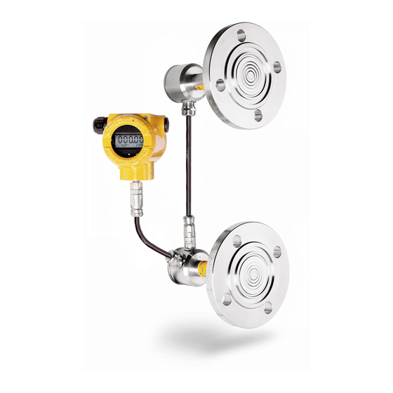
EN.IX.APM.2 TRANSMITTER DESIGN The modular differential pressure transmitters consist of: central unit HUB two pressure transmitters PC1, PC2. The basic central unit HUB components are: housing made of 316 (1.4401) stainless steel or aluminium, electronic module. Transmitters in aluminium, steel enclosures are allowed for II and III group. -
Page 8: Transmitter Protection Level (Epl) And Hazardous Areas
EN.IX.APM.2 TRANSMITTER PROTECTION LEVEL (EPL) AND HAZARDOUS AREAS Ga/Gb EPL protection level means that the transmitter can be installed in Zone 1 or 2, and transmitter process connectors of PC1, PC2 transmitters, can connect to Zone 0. Da EPL protection level means that the transmitter and process connector can be installed in Zone 20 or 21. -
Page 9: Intrinsically-Safe Exi Transmitters According To Certificate Jshp 22 Atex 0051X
EN.IX.APM.2 INTRINSICALLY-SAFE Exi TRANSMITTERS ACCORDING 8.1. TO CERTIFICATE JSHP 22 ATEX 0051X 8.2. Standards used for assessment The transmitters are manufactured in compliance with the following standards: EN IEC 60079-0:2018; (IEC 60079-0:2017 ed. 7.0), EN 60079-11:2012; (IEC 60079-11:2011 ed. 6.0.). 8.3. -
Page 10: Permissible Parameters Of Exi Transmitters
EN.IX.APM.2 PERMISSIBLE PARAMETERS OF Exi TRANSMITTERS. Table 2. Permissible input parameters of an Exi transmitter. Maximum Linear power Trapezoidal Orthogonal power surface supply power supply supply temperature Ui=30V Ui=24V, U =48V Ui=24V Ui=24V Temperature Ii=0,1A Ii=0,05A Ii=0,025A Ii=0,05A of the class Pi=0,75W Pi=0,6W... -
Page 11: Orthogonal Power Supply Example
EN.IX.APM.2 If U ≤ 1/2U have the following relations: − U Resistance Rw: 9.3. Orthogonal power supply example Uo = 24V Io = 25mA Po = 0,6W Uo = 24V Io = 50mA Po = 1,2W Orthogonal power supply means that the voltage of an intrinsically safe power adapter does not change until the current limiter is activated. - Page 12 EN.IX.APM.2 The electrical system for connecting transmitters should meet installation requirements of applicable standards. No repairs or alterations to the transmitter electrical system are permitted. Only the manufacturer or a facility authorized by the manufacturer may assess damages and repair the device. “Version SA”...
-
Page 13: Flameproof Exd Transmitters According To Certificates Jshp 22 Atex 0051X
EN.IX.APM.2 FLAMEPROOF Exd TRANSMITTERS ACCORDING TO 10.1. CERTIFICATES JSHP 22 ATEX 0051X 10.2. Standards used for assessment The transmitters are manufactured in compliance with the following standards: EN IEC 60079-0:2018; (IEC 60079-0:2017 ed. 7.0), EN 60079-11:2012; (IEC 60079-11:2011 ed. 6.0.), EN 60079-1:2014;... -
Page 14: 11.2. Power Supply, Connection And Operation Of Exd Transmitters
EN.IX.APM.2 11.2. Power supply, connection and operation of Exd transmitters Connect the transmitter according to the wiring diagram ( ). The transmitter Figure 6 electrical connections in potentially explosive zones should be made by personnel having necessary knowledge and experience in this respect. The transmitter should be properly grounded by means of a grounding terminal. - Page 15 Table 5. As a blinding plug, an Aplisens plug supplied with the transmitter or a certified blinding plug compliant with the list of equivalent blinding plugs in Table 6 can be used.
-
Page 16: Additional Information
EN.IX.APM.2 Table 5. List of equivalent cable entries Cable entry type Manufacturer Thread Designation Certificate no. CMP- M20x1.5 Exd IIC Gb A2F, A2FRC CML 18ATEX1321X (1/2” NPT) Products Exta IIIC Da CMP- M20x1.5 Exd IIC Gb SS2K CML 18ATEX1321X (1/2” NPT) Products Exta IIIC Da CMP-... -
Page 17: History Of Revisions
EN.IX.APM.2 12.2. History of revisions Revision Document revision Description of changes 01.A.001/2022.09 Initial document version. Prepared by DKD, DCF. Revision 01.A.001/2022.09...
Need help?
Do you have a question about the APM-2 and is the answer not in the manual?
Questions and answers