Table of Contents
Advertisement
Quick Links
Advertisement
Table of Contents

Related Manuals for EDAN SE-1010


Summary of Contents for EDAN SE-1010
- Page 2 This manual will help you understand the operation and maintenance of the product better. It is reminded that the product shall be used strictly complying with this manual. User’s operation failing to comply with this manual may result in malfunction or accident for which EDAN INSTRUMENTS, INC. (hereinafter called EDAN) can not be held liable.
- Page 3 Terms Used in this Manual This guide is designed to give key concepts on safety precautions. WARNING A WARNING label advises against certain actions or situations that could result in personal injury or death. CAUTION A CAUTION label advises against actions or situations that could damage equipment, produce inaccurate data, or invalidate a procedure.
-
Page 4: Table Of Contents
2.2 ECG Sampling Box Appearance..................10 2.3 Features ..........................13 Chapter 3 Assembling SE-1010 PC ECG System..............15 Chapter 4 Installing SE-1010 PC ECG Software ..............17 4.1 System Running Environment ..................17 4.1.1 Requirements on the Hardware of the PC............... 17 4.1.2 Requirements on the Software of the PC .............. - Page 5 6.5.4 Specifying Speed..................... 36 6.5.5 Recording ECG Data....................36 6.5.6 Freezing and Previewing ECG................37 6.5.7 Stopping Sampling Data ..................38 6.5.8 Printing ECG Waves ....................38 6.6 Analyzing ECG Data......................39 6.6.1 Analyzing Normal ECG ..................39 6.6.1.1 Viewing the Waveform.................. 39 6.6.1.2 About the Average Template Interface ............
- Page 6 7.1 Viewing Lead Placement Information................74 7.2 Selecting a Patient Record to Start a New Test ..............75 7.2.1 Setting Target HR....................76 7.2.2 Setting Normal BP ....................76 7.2.3 Setting a Protocol ....................77 7.2.4 Setting Post J ......................77 7.2.5 Setting BP Sampling Mode ..................
- Page 7 8.9 Viewing an Examination Record..................106 Chapter 9 Configuring the System ................... 107 9.1 Basic Information Setup....................107 9.1.1 Setting Basic Information ..................108 9.1.2 Setting ID Mode....................109 9.1.3 Setting Name Mode....................110 9.1.4 Selecting D.O.B ....................110 9.1.5 Setting Language....................111 9.1.6 Specifying the Storage Path of the ECG Data ............
- Page 8 11.2 Cleaning and Maintaining the Patient Cable and Reusable Electrodes ......126 11.3 Disinfection ........................127 Chapter 12 Accessories ......................128 Chapter 13 Warranty and Service Policy ................129 13.1 Warranty ........................129 13.2 Service Policy........................ 129 Chapter 14 Recommended Optional Accessories..............131 Appendix 1 Technical Specifications ..................
-
Page 9: Chapter 1 Safety Guidance
This chapter provides important safety information related to the use of SE-1010 PC ECG. 1.1 Intended Use SE-1010 PC ECG is a PC-based diagnostic tool intended to acquire, process and store ECG signals from adult and pediatric patients undergoing stress exercise test or resting test. SE-1010 PC ECG is intended to be used only in hospitals and healthcare facilities by doctors and trained healthcare professionals. - Page 10 SE-1010 PC ECG User Manual Safety Guidance WARNING EXPLOSION HAZARD - Do not use the system in the presence of flammable anesthetic mixtures with oxygen or other flammable agents. SHOCK HAZARD - The power receptacle must be a hospital grade grounded outlet.
-
Page 11: General Cautions
SE-1010 PC ECG User Manual Safety Guidance WARNING 21. The summation of leakage current should never exceed leakage current limits while several other units are used at the same time. 22. The equipment is protected against malfunctions caused by electrosurgery according to the clause 36.202.101 in the standard IEC60601-2-25. - Page 12 SE-1010 PC ECG User Manual Safety Guidance CAUTION g) Test the enclosure leakage current according to IEC/EN 60601-1: Limit: NC 100 μA, SFC 500 μA. h) Test the patient leakage current according to IEC/EN 60601-1: Limit: NC a.c. 10 μA, d.c. 10 μA; SFC a.c. 50 μA, d.c. 50 μA.
-
Page 13: Preparation And Operation Warnings (For Exercise Ecg)
SE-1010 PC ECG User Manual Safety Guidance 1.2.3 Preparation and Operation Warnings (for Exercise ECG) WARNING Ensure that the main unit and the treadmill are effectively grounded. Test the emergency stop switch of the treadmill before using the system. During the exercise testing, ensure that there are at least 2 experienced physicians present. -
Page 14: Contraindications (For Exercise Ecg)
SE-1010 PC ECG User Manual Safety Guidance 1.2.4 Contraindications (for Exercise ECG) Absolute Contraindications: 1. Acute MI (within 2 days) 2. High-risk unstable angina 3. Hemodynamic compromise caused by uncontrolled cardiac arrhythmia 4. Active endocarditis 5. Symptomatic severe aortic stenosis 6. -
Page 15: List Of Symbols
SE-1010 PC ECG User Manual Safety Guidance 1.3 List of Symbols Equipment or part of CF type with defibrillator proof Caution Consult Instructions for Use Recycle Part Number Serial Number Date of Manufacture Manufacturer Authorized Representative in the European Community... -
Page 16: Chapter 2 Introduction
ECG will change abnormally. Therefore, with the function of exercise ECG, SE-1010 PC ECG can also be used to diagnose concealed coronary heart disease and atypical angina pectoris, prescribe the workload for patients with myocardial infarction before they leave hospital, and assess the effect of the treatment. - Page 17 SE-1010 PC ECG User Manual Introduction SE-1010 PC ECG System Treadmill or Ergometer (Manually Configured) Serial Patient Cable (for exercise ECG only) Patient Cable BP Monitor Cable PC (Manually ECG Sampling Box (Manually Configured) Configured) Cable USB Cable (for exercise...
-
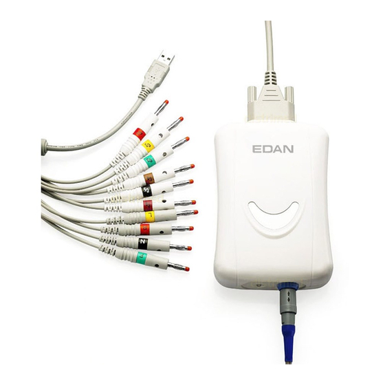
Page 18: Ecg Sampling Box Appearance
SE-1010 PC ECG User Manual Introduction 2.2 ECG Sampling Box Appearance ECG Sampling Box Appearance Front Panel Lamp USB Socket Name Explanation When the ECG sampling box is powered by the PC, the lamp Lamp will be lit. USB Socket... - Page 19 SE-1010 PC ECG User Manual Introduction USB Socket Definitions of corresponding pins: Signal Signal WARNING 1. When the computer connected to the USB cable is powered on, do not connect the USB cable to the ECG sampling box; when the system is powered on, do not disconnect the USB cable from the ECG sampling box.
- Page 20 SE-1010 PC ECG User Manual Introduction : Caution Patient Cable Socket Definitions of corresponding pins: Signal Signal Signal C2 / V2 F / LL C3 / V3 C1 / V1 or NC C4 / V4 C1 / V1 C5 / V5...
-
Page 21: Features
SE-1010 PC ECG User Manual Introduction WARNING 1. Accessory equipment connected to the analog and digital interfaces must be certified according to the respective IEC/EN standards (e.g. IEC/EN 60950 for data processing equipment and IEC/EN 60601-1 for medical equipment). Furthermore all configuration shall comply with the valid version of the standard IEC/EN 60601-1-1. - Page 22 QT Dispersion, Vector ECG, Time Vector ECG, HRT analysis, HRV analysis and Signal Averaged ECG (Only for resting ECG) The following features are only for the exercise test function of SE-1010 PC ECG Automatically controlling and adjusting the speed and the elevation of the treadmill Supporting many kinds of treadmills and ergometers Providing classical exercise protocols;...
-
Page 23: Chapter 3 Assembling Se-1010 Pc Ecg System
SE-1010 PC ECG User Manual Assembling SE-1010 PC ECG System Chapter 3 Assembling SE-1010 PC ECG System Patient Cable for Resting ECG Patient Cable for Exercise ECG ECG Sampling Box Cable for Exercise ECG Cable for Resting ECG For resting ECG, 1. - Page 24 SE-1010 PC ECG User Manual Assembling SE-1010 PC ECG System 2. Insert plug 8 of the cable into socket 4 of the ECG sampling box. 3. Insert plug 9 of the cable into the USB socket of the PC. 4. Connect a printer to the PC.
-
Page 25: Chapter 4 Installing Se-1010 Pc Ecg Software
SE-1010 PC ECG User Manual Installing SE-1010 PC ECG Software Chapter 4 Installing SE-1010 PC ECG Software 4.1 System Running Environment 4.1.1 Requirements on the Hardware of the PC Pentium P4, Celeron D 310 or above CPU: 512MB or above... -
Page 26: About Installation Interface
Note: During the installation in Windows 7/Vista, only if Add user to the SQL Server Administrator role is selected, can the database be available. Click on the Help button to see the installation guide. For details on installing SE-1010 software, please refer to <<SE-1010 PC ECG Installation Guide>>. - 18 -... -
Page 27: Chapter 5 Preparations Before Operation
SE-1010 PC ECG User Manual Preparations Before Operation Chapter 5 Preparations Before Operation 5.1 Preparing the Patient 5.1.1 Instructing the Patient Before attaching the electrodes, greet the patient and explain the procedure. Explaining the procedure decreases the patient’s anxiety. Reassure the patient that the procedure is painless. -
Page 28: Attaching Electrodes (For Resting Ecg)
SE-1010 PC ECG User Manual Preparations Before Operation Main Cable Lead Wires Screw Connecting to Electrodes Connecting ECG Sampling Box Patient Cable for Resting ECG Main Cable Lead Wires Screw Connecting to Electrodes Connecting to the ECG Sampling Box Patient Cable for Exercise ECG 1. -
Page 29: Wilson Lead System
SE-1010 PC ECG User Manual Preparations Before Operation Table 5-1 Electrodes and Their Identifiers and Color Codes European American Identifier Color Code Identifier Color Code WILSON FRANK Right arm Right arm White Left arm Left arm Yellow Black N or RF... -
Page 30: Frank Lead System
SE-1010 PC ECG User Manual Preparations Before Operation 5.3.2 Frank Lead System FRANK lead system is usually adopted when PC ECG is used to produce VCG. The conventional letter designations for the electrodes and their respective positions are: E/C2: at the front midline... - Page 31 SE-1010 PC ECG User Manual Preparations Before Operation 2. Daub the electrode area on the limb with gel evenly. 3. Place a small amount of gel on the metal part of the limb electrode clamp. 4. Connect the electrode to the limb, and make sure that the metal part is placed on the electrode area above the ankle or the wrist.
-
Page 32: Attaching Electrodes To The Patient (For Exercise Ecg)
SE-1010 PC ECG User Manual Preparations Before Operation 2) Connect the snap/banana socket adapter to the disposable electrode. 3) Clean the electrode area at the back midline with 75% alcohol. 4) Attach the disposable electrode to the electrode area at the back midline. - Page 33 SE-1010 PC ECG User Manual Preparations Before Operation Table 5-2 Electrodes and their identifiers and color codes European American Electrodes Color code Electrodes Color code White Yellow Black N or RF Black Green Green White/Red Brown/Red White/Yellow Brown/Yellow White/Green Brown/Green...
-
Page 34: Inspection Before Test
SE-1010 PC ECG User Manual Preparations Before Operation electrodes to the lead wires. Clean the electrode areas on the body surface with 75% alcohol. Attach the disposable electrodes to the electrode sites. Note: The quality and the placement of the electrode will directly influence the quality of exercise ECG. - Page 35 SE-1010 PC ECG User Manual Preparations Before Operation 4) Electrodes: ♦ Check whether all electrodes are connected to lead wires of the patient cable correctly. ♦ Ensure that the electrodes do not contact. 5) Patient: ♦ The patient should not come into contact with conducting objects such as earth, metal parts etc.
-
Page 36: Chapter 6 Operation Instructions For Resting Ecg
Chapter 6 Operation Instructions for Resting Double-click on the shortcut icon on the desktop. is the desktop icon for SE-1010 PC ECG. Figure 6-1 Initial Interface The toolbar contains six buttons. From left to right, they are New Patient, STAT ECG, Data Manager, System Setting, Lead Placement and Exit. -
Page 37: Viewing Lead Placement Information
SE-1010 PC ECG User Manual Operation Instructions for Resting ECG 6.1 Viewing Lead Placement Information 1. Click on the Lead Placement button on the initial interface to display the Lead Placement window. 2. Click on Wilson lead system, Frank lead system or Exercise ECG lead system to view the lead placement information in the corresponding system. - Page 38 SE-1010 PC ECG User Manual Operation Instructions for Resting ECG Figure 6-2 Data Manager Interface 1. Select a search item in the pull-down list on the Data Manager interface. Then all the patient records which meet the search condition are listed in the patient information list.
- Page 39 SE-1010 PC ECG User Manual Operation Instructions for Resting ECG conditions, and click on the Search button, and all the patient records which meet the conditions will be displayed in the patient information list. 4. Click on the patient record in the patient information list and click on the Select button to open the Patient information interface.
-
Page 40: Entering New Patient Information
SE-1010 PC ECG User Manual Operation Instructions for Resting ECG Figure 6-3 Patient Information Interface 6.3 Entering New Patient Information If the patient is a new one, you can click on the New Patient button on the initial interface (Figure 6-1) to display the Patient information interface. - Page 41 SE-1010 PC ECG User Manual Operation Instructions for Resting ECG Then you need to input the patient’s related information. 1. Input basic information, such as patient ID, name, sex, age, etc. User-defined 1 and User-defined 2: You can input other related information such as patients’...
-
Page 42: Selecting Sampling Type
SE-1010 PC ECG User Manual Operation Instructions for Resting ECG 6.4 Selecting Sampling Type You can select a sampling type on the Patient information interface. 6.5 Sampling Resting ECG After inputting the patient information, click on the OK button on the Patient information interface to open the ECG sampling interface. -
Page 43: Specifying Display Mode
SE-1010 PC ECG User Manual Operation Instructions for Resting ECG Figure 6-4 Pre-Sampling Interface 6.5.1 Specifying Display Mode There are five display modes including 12*1, 6*2, 3*4, 6*1, and 3*1. When the display mode is set to 12*1, 12-channel ECG waves are displayed on one screen simultaneously. -
Page 44: Specifying Lowpass Filter
SE-1010 PC ECG User Manual Operation Instructions for Resting ECG When the display mode is set to 3*1, 3-channel ECG waves are displayed on one screen simultaneously. 6.5.2 Specifying Lowpass Filter Lowpass Filter restricts the bandwidth of input signals. The cutoff frequency can be set to 25Hz, 35Hz, 45Hz, 75Hz, 100Hz, or 150Hz. -
Page 45: Freezing And Previewing Ecg
SE-1010 PC ECG User Manual Operation Instructions for Resting ECG 9.1.5, “Specifying the Storage Path of the ECG Data”. Figure 6-5 ECG Sampling Interface Note: After you click on the Start button, the system will save the sampled ECG data. If you don’t click on the Start button, the system won’t save the sampled ECG data. -
Page 46: Stopping Sampling Data
SE-1010 PC ECG User Manual Operation Instructions for Resting ECG Figure 6-6 Wave Review Interface Click on Exit to return to the ECG sampling interface. 6.5.7 Stopping Sampling Data After clicking on the Start button, there are two ways to stop sampling data. -
Page 47: Analyzing Ecg Data
SE-1010 PC ECG User Manual Operation Instructions for Resting ECG “Printer Setup”. 6.6 Analyzing ECG Data You can open the ECG analysis interface in one of the following three ways: 1. Click on the Start button, and then the system will stop sampling ECG and display the ECG analysis interface automatically after the ECG sampling time is over. - Page 48 SE-1010 PC ECG User Manual Operation Instructions for Resting ECG Figure 6-7 Normal ECG - Waveform Interface You can choose a speed, a gain and a display mode for the displayed waves. Click on the Measure button on the Waveform interface (Figure 6-7). Click on one point on the wave, and then drag the mouse to another point.
- Page 49 SE-1010 PC ECG User Manual Operation Instructions for Resting ECG Designation Description Heart Rate Heart Rate P Duration P-wave duration of the current lead PR Dur. P-R interval of the current lead QRS Dur. QRS complex duration of the current lead...
-
Page 50: About The Average Template Interface
SE-1010 PC ECG User Manual Operation Instructions for Resting ECG To Edit the Diagnosis Result 1. Enter your own opinions in the diagnosis textbox, and then click on the Save button. 2. Or double-click on the necessary results required to be added in the Glossary textbox, and the selected results will be displayed in the diagnosis textbox, and then click on the Save button. -
Page 51: About The Detail Information Interface
SE-1010 PC ECG User Manual Operation Instructions for Resting ECG You can drag marker lines of P1, P2, Q, S, T1 and T2 on average templates. P1 is the start point of P wave, P2 is the end point of P wave, Q marks the position of Q point, S marks the position of S point, T1 is the start point of T wave and T2 is the end point of T wave. -
Page 52: Previewing Normal Ecg
SE-1010 PC ECG User Manual Operation Instructions for Resting ECG 6.6.1.4 Previewing Normal ECG Click on the Preview button to display the normal ECG preview interface. is the toolbar on the normal ECG preview interface. 1. Click on the Next Page button on the toolbar to switch to the next preview page. -
Page 53: Analyzing Qt Dispersion
SE-1010 PC ECG User Manual Operation Instructions for Resting ECG Figure 6-11 Average Template & Position Marker - the Second Page 6.6.2 Analyzing QT Dispersion Click on the QT Dispersion button to open the QT Dispersion interface. QT Dispersion: The difference between the largest QT interval and the shortest QT interval based on the synchronous 12-lead surface ECG. -
Page 54: Editing Waveform On The Qt Dispersion Interface
SE-1010 PC ECG User Manual Operation Instructions for Resting ECG Figure 6-12 QT Dispersion Interface 6.6.2.1 Editing Waveform on the QT Dispersion Interface There are red and blue triangle icons on top of the displayed ECG waves. You can click on the triangle icon to change the color. -
Page 55: About Qt Value
SE-1010 PC ECG User Manual Operation Instructions for Resting ECG 6.6.2.2 About QT Value QT values of 12 leads and QT dispersion (QTd) are displayed as the left figure shows. 6.6.2.3 Previewing QT Dispersion Click on the Preview button on the QT Dispersion interface to open the QT Dispersion preview interface. -
Page 56: Analyzing Frequency Ecg
SE-1010 PC ECG User Manual Operation Instructions for Resting ECG Figure 6-13 QT Dispersion Preview Interface 6.6.3 Analyzing Frequency ECG Click on the Frequency ECG button to open the Frequency ECG interface. Frequency ECG displays characteristic waves of ECG signal spectrum. - Page 57 SE-1010 PC ECG User Manual Operation Instructions for Resting ECG Figure 6-14 Frequency ECG - Two-lead Comparison Interface Every parameter of Frequency ECG is shown in the following table. Designation Definition If the first peak value is lower than 90% of the second peak value, it is positive (‘+’).
- Page 58 SE-1010 PC ECG User Manual Operation Instructions for Resting ECG If the phase shift in the range of 6~18Hz exceeds 90 degrees, Phase Shift it is positive. Otherwise it is minus. If the coherence value of the fundamental (the position of the first peak in power spectrum) is less than 0.8, it is positive.
-
Page 59: About 12-Lead Power Spectrum Interface
SE-1010 PC ECG User Manual Operation Instructions for Resting ECG 6.6.3.2 About 12-lead Power Spectrum Interface The 12-lead power spectrum interface displays the power spectrum of 12-lead ECG waves. Figure 6-15 Frequency ECG - 12-lead Power Spectrum 6.6.3.3 Previewing Frequency ECG Click on the Preview button to open the Frequency ECG preview interface. - Page 60 SE-1010 PC ECG User Manual Operation Instructions for Resting ECG Figure 6-16 Two-lead Comparison Report Figure 6-17 12-lead Power Spectrum Report - 52 -...
-
Page 61: Analyzing High Frequency Ecg
SE-1010 PC ECG User Manual Operation Instructions for Resting ECG 6.6.4 Analyzing High Frequency ECG In a conventional electrocardiogram, only these ECG signals, of which the amplitude is in the millivolt range and the frequency is less than 100 Hz, are visible. Those ECG signals, of which the amplitude is in the microvolt range and the frequency is between 150Hz and 250Hz, are invisible. - Page 62 SE-1010 PC ECG User Manual Operation Instructions for Resting ECG You can choose the lead group, the gain and the speed of the waves displayed in the bottom part of the HF ECG analysis interface. is the statistic data of beadings, notches and slurs. You can change a value by double-clicking on the value.
-
Page 63: Analyzing Hrv
SE-1010 PC ECG User Manual Operation Instructions for Resting ECG Figure 6-19 HF ECG Report 6.6.5 Analyzing HRV Click on HRV to display the HRV ECG analysis interface. The HRV ECG analysis interface includes two tabs: Auto diagnosis result and Waveform. -
Page 64: Editing The Hrv Data On The Analysis Interface
SE-1010 PC ECG User Manual Operation Instructions for Resting ECG 6.6.5.1 Editing the HRV Data on the Analysis Interface Figure 6-20 Analysis Interface of HRV Designation Definition Sampling time Set sampling time Total beat number during the measuring course Total Beat... -
Page 65: Editing The Hrv Waveform On The Waveform Interface
SE-1010 PC ECG User Manual Operation Instructions for Resting ECG Standard LF power LF (norm) Standard HF power HF (norm) H- Doctor Diagnosis Field 1. Enter your own opinions in the Auto diagnosis textbox, and then click on the Save button. -
Page 66: Previewing Hrv
SE-1010 PC ECG User Manual Operation Instructions for Resting ECG 6.6.5.3 Previewing HRV Click on the Preview button to open the HRV preview interface. is the toolbar on the HRV preview interface. 1. Click on the Zoom In button on the toolbar to magnify the preview page. -
Page 67: Analyzing Hrt
SE-1010 PC ECG User Manual Operation Instructions for Resting ECG 6.6.6 Analyzing HRT Heart Rate Turbulence (HRT) is a physiological, biphasic response of the sinus node to the premature ventricular contractions. It includes a short initial acceleration followed by a deceleration of the heart rate. - Page 68 SE-1010 PC ECG User Manual Operation Instructions for Resting ECG Click on HRT to display the HRT analysis interface. Figure 6-23 HRT Analysis Interface A- HRT Tachogram B- Individual PVC C- Risk Factors You can select Average Histogram or Single Histogram.
-
Page 69: Analyzing Vector Ecg
SE-1010 PC ECG User Manual Operation Instructions for Resting ECG Figure 6-24 HRT Preview Interface 6.6.7 Analyzing Vector ECG Click on the VCG button on the ECG analysis interface to display the VCG analysis interface. Vector ECG displays 3D image of ECG activity. -
Page 70: Displaying Vector Ecg With All Plane And All Loop
SE-1010 PC ECG User Manual Operation Instructions for Resting ECG 6.6.7.1 Displaying Vector ECG with All Plane and All Loop Set the plane to ALL and the loop to ALL. Figure 6-25 displays Vector ECG with the plane of ALL and the loop of ALL. - Page 71 SE-1010 PC ECG User Manual Operation Instructions for Resting ECG Designation Definition Max Vector The position of the maximal amplitude of QRS/P/T loop (mV) Amplitude The amplitude of the Max vector of QRS/P/T loop (mV) Angle The angle of the Max vector of QRS/P/T loop (degree)
-
Page 72: Displaying Vector Ecg With Frontal Plane And Qrs Loop
SE-1010 PC ECG User Manual Operation Instructions for Resting ECG 0.04 (amplitude) The amplitude at 0.04s from QRS loop 0.04 (angle) The angle at 0.04s from QRS loop Start Vector Start point of QRS loop End Vector End point of QRS loop... -
Page 73: Displaying 3D Vector Ecg
SE-1010 PC ECG User Manual Operation Instructions for Resting ECG percentages of QRS loop in every quadrant. 20 mm/mV indicates the magnified multiple (gain). The red curve is QRS loop. You can click on the Zoom in button or the Zoom out button to change the gain of the displayed graphics. -
Page 74: Previewing Vector Ecg
SE-1010 PC ECG User Manual Operation Instructions for Resting ECG 6.6.7.4 Previewing Vector ECG Click on the Preview button to open the VCG preview interface. is the toolbar on the VCG preview interface. 1. Click on the Zoom In button on the toolbar to magnify the preview page. - Page 75 SE-1010 PC ECG User Manual Operation Instructions for Resting ECG You can choose the speed and the gain of the displayed waves. Figure 6-28 Time Vector ECG Interface Click on the Preview button to display the TVCG preview interface. is the toolbar on the TVCG preview interface.
-
Page 76: Analyzing Signal Averaged Ecg
SE-1010 PC ECG User Manual Operation Instructions for Resting ECG Figure 6-29 Time Vector ECG Preview Interface 6.6.9 Analyzing Signal Averaged ECG SAECG is also called Ventricular Late Potential (VLP). Click on SAECG to open the SAECG analysis interface. The SAECG analysis interface includes two tabs: Time domain and Frequency domain. -
Page 77: About The Time Domain Interface
SE-1010 PC ECG User Manual Operation Instructions for Resting ECG 6.6.9.1 About the Time Domain Interface Click on the Time domain tab to open the time domain interface. Figure 6-30 Time Domain Interface There are four vertical lines and one horizontal fixed measurement line on this interface. -
Page 78: Previewing Signal Averaged Ecg
SE-1010 PC ECG User Manual Operation Instructions for Resting ECG Figure 6-31 Frequency Domain Interface You can drag the green vertical lines on the ECG wave, and the corresponding parameters in the right part and the 3D graph in the bottom part will change. -
Page 79: Printing Ecg Reports
SE-1010 PC ECG User Manual Operation Instructions for Resting ECG Figure 6-32 Signal Averaged ECG Report 6.6.10 Printing ECG Reports 1. Choose Start > Printers and Faxes, and then right-click on the icon of the printer used, and select Set as Default Printer. Then close the Printers and Faxes interface. -
Page 80: Saving Ecg Reports
SE-1010 PC ECG User Manual Operation Instructions for Resting ECG 2. Click on the Print button on the analysis interface to print an ECG report. 3. Or click on the Print button on the preview interface to print an ECG report. -
Page 81: Sampling Stat Ecg
SE-1010 PC ECG User Manual Operation Instructions for Resting ECG If you select Send, the sampled data will be sent by email (outlook express) when it is saved to the designated directory. During the saving and sending course, the system will give the hint information. -
Page 82: Chapter 7 Operation Instructions For Exercise Ecg
SE-1010 PC ECG User Manual Operation Instructions for Exercise ECG Chapter Operation Instructions Exercise ECG The exercise ECG function is optional. It is available only if you purchased this function. 7.1 Viewing Lead Placement Information 1. Click on the Lead Placement button on the initial interface to display the Lead Placement window. -
Page 83: Selecting A Patient Record To Start A New Test
SE-1010 PC ECG User Manual Operation Instructions for Exercise ECG 7.2 Selecting a Patient Record to Start a New Test 1. You can select a patient record from the database to start a new test. The operation steps are the same as those of resting ECG. -
Page 84: Setting Target Hr
SE-1010 PC ECG User Manual Operation Instructions for Exercise ECG 7.2.1 Setting Target HR The system applies the following formulas to calculate the target heart rate. 220 and 85 are default values, and you can modify them in different situations on the Exercise ECG Setting interface. -
Page 85: Setting A Protocol
SE-1010 PC ECG User Manual Operation Instructions for Exercise ECG 7.2.3 Setting a Protocol Select a protocol from the pull-down list 7.2.4 Setting Post J Select a Post J value from the Post J pull-down list on the Exercise ECG Setting interface. -
Page 86: Setting Auto Printing
SE-1010 PC ECG User Manual Operation Instructions for Exercise ECG 7.2.7 Setting Auto Printing Select Auto print to print ECG reports automatically. 7.3 Entering New Patient Information If the patient is a new one, 1. Click on the New Patient button on the initial interface (Figure 6-1) to display the Patient information interface. - Page 87 SE-1010 PC ECG User Manual Operation Instructions for Exercise ECG - 79 -...
-
Page 88: Pre-Sampling Ecg
SE-1010 PC ECG User Manual Operation Instructions for Exercise ECG 7.4 Pre-sampling ECG Figure 7-1 Pre-Sampling Interface 1. Select a display mode from the display mode pull-down list 2. Select a gain from the gain pull-down list 3. Select a speed from the speed pull-down list... -
Page 89: Pretest Phase
SE-1010 PC ECG User Manual Operation Instructions for Exercise ECG 4. Select a lowpass filter from the lowpass filter pull-down list 7.5 Pretest Phase Notes: 1. If the test time exceeds 40 minutes, the system will enter the monitoring status. Data will not be saved or printed any more. -
Page 90: Viewing The Heart Rate And The Blood Pressure
SE-1010 PC ECG User Manual Operation Instructions for Exercise ECG 7.5.1 Viewing the Heart Rate and the Blood Pressure 1. View the heart rate in the heart rate field . The middle number is the current heart rate, and the right number is the target heart rate. -
Page 91: Viewing Other Information
SE-1010 PC ECG User Manual Operation Instructions for Exercise ECG 7.5.2 Viewing Other Information 1. If a treadmill is used, view other information such as the stage time, exercise time, total time, PVC/min, speed/slope, and Max ST/Min ST. 2. If an ergometer is used, view other information such as the stage time, exercise time, total time, power/RPM, and Max ST/Min ST. - Page 92 SE-1010 PC ECG User Manual Operation Instructions for Exercise ECG 3. Click on the Template button, and the average waves of 12 leads and the calibration lines will be displayed. The average waves will be updated every 10 seconds. Right-click on the average wave field to display the lead group menu, and then you can select other leads.
-
Page 93: Printing The Pretest Report
SE-1010 PC ECG User Manual Operation Instructions for Exercise ECG 4. Click on the ST Trend button to display the ST trend. Right-click on the ST trend field to display the lead group menu, and then you can select other leads. -
Page 94: Recovery Phase
SE-1010 PC ECG User Manual Operation Instructions for Exercise ECG 2. View the heart rate and BP of the patient. For details, see Section 7.5.1, “Viewing the Heart Rate and the Blood Pressure”. Notes: 1. If the current heart rate exceeds the target heart rate, the hint The current HR has exceeded the target HR! will appear on the sampling interface and the background color of the heart rate field will change from white to yellow. -
Page 95: Exiting The Exercise Test
SE-1010 PC ECG User Manual Operation Instructions for Exercise ECG Note: If the test time exceeds 40 minutes, the system will enter the monitoring status. Data will not be saved or printed any more. 7.8 Exiting the Exercise Test During the exercise test, click on the STOP button to display the following dialog box. Enter the reasons for termination in the dialog box or select a reason from the pull-down list. -
Page 96: About Analysis Interface
SE-1010 PC ECG User Manual Operation Instructions for Exercise ECG 7.9 About Analysis Interface 7.9.1 About Summary Interface 1. Click on Summary to open the summary interface. Figure 7-2 Summary Interface Click on the Measure button and then click on one point on the wave, and then drag the mouse to another point. - Page 97 SE-1010 PC ECG User Manual Operation Instructions for Exercise ECG 5. Enter diagnosis results in the Diagnosis textbox, and then click on Save. 6. Or double-click on the necessary results required to be added in the Glossary textbox, and the selected results will be displayed in the Diagnosis textbox, and then click on the Save button.
- Page 98 SE-1010 PC ECG User Manual Operation Instructions for Exercise ECG Figure 7-3 Summary Report - 90 -...
-
Page 99: About St Analysis Interface
SE-1010 PC ECG User Manual Operation Instructions for Exercise ECG Figure 7-4 Current Wave Report Note: The diagnosis result is displayed in the diagnosis field of the summary report. 7.9.2 About ST Analysis Interface 1. Click on the ST analysis button to display the ST analysis interface. - Page 100 SE-1010 PC ECG User Manual Operation Instructions for Exercise ECG Figure 7-5 ST Analysis Interface 2. Click on Pretest to display 12-lead ST analysis waves of the pretest phase. 3. Click on Exercise to display 12-lead ST analysis waves of the exercise phase.
-
Page 101: About All View Review Interface
SE-1010 PC ECG User Manual Operation Instructions for Exercise ECG 7.9.3 About All View Review Interface 1. Click on the All View button to display the all view interface. - 93 -... - Page 102 SE-1010 PC ECG User Manual Operation Instructions for Exercise ECG Figure 7-6 All View Interface The all view interface displays the ECG wave of one lead from the beginning of the exercise test to the end. 2. Select a lead from the lead pull-down list to view the ECG wave of the lead.
- Page 103 SE-1010 PC ECG User Manual Operation Instructions for Exercise ECG range will be marked with two red lines. Then click on the Zoom in button to display the amplified ECG segment. Drag the bottom scroll bar to view the whole amplified ECG waves.
-
Page 104: About Trend Interface
SE-1010 PC ECG User Manual Operation Instructions for Exercise ECG seconds can be reviewed by clicking on the Previous Page/Next Page button. 7.9.4 About Trend Interface Click on the Trend button to display the trend interface. Figure 7-7 Trend Interface You can observe 12-lead trend of the exercise test on the trend interface. -
Page 105: Previewing Ecg Reports
SE-1010 PC ECG User Manual Operation Instructions for Exercise ECG Figure 7-8 ECG Strip Interface 1. Click on Pretest to display strip waves of the pretest phase. 2. Click on Exercise to display strip waves of the exercise phase. 3. Click on Recovery to display strip waves of the recovery phase. -
Page 106: Saving Ecg Reports
SE-1010 PC ECG User Manual Operation Instructions for Exercise ECG 7.9.8 Saving ECG Reports You can save an ECG report by clicking on the Report Save button. For details, please refer to Section 6.6.11, “Saving ECG reports”. 7.9.9 Exiting the Analysis Interface Click on the Exit button on the analysis interface to return to the initial interface. -
Page 107: Chapter 8 Processing Patient Records
SE-1010 PC ECG User Manual Processing Patient Records Chapter 8 Processing Patient Records Click on the Data Manager button on the initial interface (Figure 6-1) to open the Data Manager interface (Figure 8-1). Figure 8-1 Data Manager Interface Click on a patient record in the patient information list, and then all the examination records of the patient will be displayed in the examination record list. - Page 108 SE-1010 PC ECG User Manual Processing Patient Records list. 2. Or select a search item in the pull-down list , enter the corresponding information in the right textbox, and then click on the Search button. All the patient records which meet the conditions will be displayed in the patient information list.
-
Page 109: Modifying Patient Records
SE-1010 PC ECG User Manual Processing Patient Records 4. Or you can click on Physician or Examination Record , and choose the doctor name or examination types, all the patient records which meet the conditions will be displayed in the patient information list. -
Page 110: Deleting Records
SE-1010 PC ECG User Manual Processing Patient Records 8.3 Deleting Records Note: The deletion of records is permanent, and you can’t restore the records deleted. Please use this operation cautiously. 8.3.1 Deleting Patient Records Click on a patient record in the patient information list on the Data Manager interface, and then click on the Delete button to delete the patient record from the patient information list. -
Page 111: Merging Examination Records
SE-1010 PC ECG User Manual Processing Patient Records 8.5 Merging Examination Records Click on an examination record in the examination record list on the Data Manager interface, and click on the Merge/Assign button to display the Patient information interface. Input a patient ID and click on the OK button to assign the examination record selected to this patient. -
Page 112: Importing Ecg Data Into The Data Manager Interface
SE-1010 PC ECG User Manual Processing Patient Records 8.7 Importing ECG Data into the Data Manager Interface Click on the Import button on the Data Manager interface (Figure 8-1) to open the following window. Select the data to be imported and click on the Select button to import the data into the Data Manager interface. -
Page 113: Exporting Ecg Data From The Data Manager Interface
SE-1010 PC ECG User Manual Processing Patient Records If the data to be imported exists on the Data Manager interface, the following hint will pop up. Click on the Yes button to import the data. Click on the No button to cancel the operation. -
Page 114: Viewing An Examination Record
SE-1010 PC ECG User Manual Processing Patient Records Note: Only if the export file format is set to SCP, can the Compress check box be displayed. 8.9 Viewing an Examination Record Click on a patient record in the patient information list, and then all the records of the patient will be displayed in the examination record list. -
Page 115: Chapter 9 Configuring The System
SE-1010 PC ECG User Manual Configuring the System Chapter 9 Configuring the System Click on the System Setting button on the initial interface (Figure 6-1) to open the System Setting interface. There are six tabs on the System Setting interface: Basic Information, Sample Setting, Device, Print Setting, Others and GDT. -
Page 116: Setting Basic Information
SE-1010 PC ECG User Manual Configuring the System Figure 9-1 Basic Information Setup Interface 9.1.1 Setting Basic Information Enter information in the Hospital Name, Physician, Technician, User-Defined 1 or User-Defined 2 textbox on the basic information setup interface (Figure 9-1). -
Page 117: Setting Id Mode
SE-1010 PC ECG User Manual Configuring the System Note: Click on the New Patient button on the initial interface to open the Patient information interface as the above figure shows. 9.1.2 Setting ID Mode Set ID Create Type to Auto Create, Manually input or Auto increase. -
Page 118: Setting Name Mode
SE-1010 PC ECG User Manual Configuring the System 9.1.3 Setting Name Mode If you select First Name/Last Name, the Patient Name textbox on the Patient information interface will change into the First Name and Last Name textboxes. 9.1.4 Selecting D.O.B If you select D.O.B, the D.O.B textbox appears on the Patient information interface, and the... -
Page 119: Setting Language
SE-1010 PC ECG User Manual Configuring the System 9.1.5 Setting Language You can set the language to Chinese or English. Note: To validate the language setup, after setting, you should exit the system and open it again. 9.1.6 Specifying the Storage Path of the ECG Data Click on the Browse button on the basic information setup interface (Figure 9-1) to assign the storage path. -
Page 120: Sample Setup
SE-1010 PC ECG User Manual Configuring the System 9.2 Sample Setup Figure 9-2 Sample Setup Interface 9.2.1 Setting Filter Set filters on the sample setup interface (Figure 9-2). DFT Filter - 112 -... -
Page 121: Setting Sampling Time
SE-1010 PC ECG User Manual Configuring the System DFT filter greatly reduces the baseline fluctuations without affecting ECG signals. There are two options: Weak and Strong. Note: If DFT filter is set to Strong, the ECG data displayed on the screen is 0.85 seconds later than the real-time ECG data;... -
Page 122: Setting Hr Calculation Lead
SE-1010 PC ECG User Manual Configuring the System When PACE detection is set to Weak, the pacemaker signals are not easy to be detected. 9.2.5 Setting HR Calculation Lead You can set the HR calculation to one of the 12 standard leads: І, П, Ш, aVR, aVL, aVF, V1, V2, V3, V4, V5, or V6. -
Page 123: Device Setup
SE-1010 PC ECG User Manual Configuring the System 9.3 Device Setup Figure 9-3 Device Setup Interface 9.3.1 Setting Sampling Device Select sample device from pull-down list Sampling Device on the device setup interface (Figure 9-3). - 115 -... -
Page 124: Setting Device Type/Mode
SE-1010 PC ECG User Manual Configuring the System 9.3.2 Setting Device Type/Mode Select device type/mode from pull-down list Device Type/Device on the device setup interface (Figure 9-3). 9.3.3 Setting COM Port of Sample/Treadmill/BP Monitor Set COM port of sampling/treadmill/BP monitor in on the device setup interface (Figure 9-3). -
Page 125: Modifying A Protocol
SE-1010 PC ECG User Manual Configuring the System Enter protocol name textbox Protocol Name 2. Right-click on the grid to display the menu , click on Add Stage, and enter information in the grid. 3. Set the auto printing time of 12-lead ECG reports in the 12-lead ECG Report (First) and 12-lead ECG Report (Repeat) columns. -
Page 126: Deleting A Protocol
SE-1010 PC ECG User Manual Configuring the System 2. Double-click on an option of the phase row to be modified in the protocol list, and the pull-down list will be displayed. Select a phase and it will be displayed in the corresponding grid. -
Page 127: Restoring The Factory Settings
SE-1010 PC ECG User Manual Configuring the System 9.3.4.4 Restoring the Factory Settings Click on the Restore the default button to resume the factory settings. 9.4 Printer Setup Figure 9-4 Printer Setting Interface 9.4.1 Choosing Patient Information to be Printed The patient information is displayed on the preview interface and in the report printed out. -
Page 128: Choosing Diagnosis Information To Be Printed
SE-1010 PC ECG User Manual Configuring the System 9.4.2 Choosing Diagnosis Information to be Printed The diagnosis information is displayed on the preview interface and in the report printed out. Position Mark should be selected together with Average template, because the position mark is only used to mark the position of ECG waves in the average template. -
Page 129: Other Setup
SE-1010 PC ECG User Manual Configuring the System 9.5 Other Setup Figure 9-5 Other Setup Interface Set the height unit to cm, inch or mm. Set the weight unit to Kg, g or Pound. Set the BP unit to KPa or mmHg. -
Page 130: Gdt Setup
SE-1010 PC ECG User Manual Configuring the System 9.6 GDT Setup Figure 9-6 GDT Setup Interface Select On GDT to enable GDT features. Click on the Browse button, and then appoint the path to exchange files with EDP. Fill in the Input file name textbox to set command file name assigned by EDP to the PC ECG system. -
Page 131: Modifying The Glossary
SE-1010 PC ECG User Manual Configuring the System 9.7 Modifying the Glossary Click on Edit Diagnosis Template in the Tool (F) pull-down list on the initial interface (Figure 6-1), and then the Edit Diagnosis Template window appears. 1. Select an item, such as Other Result. Enter your own opinions in the bottom textbox, and then click on the Add button. -
Page 132: Chapter 10 Hint Information
SE-1010 PC ECG User Manual Hint Information Chapter 10 Hint Information Hint information and the corresponding causes provided by the system are listed as follows. Table 10-1 Hint Information and Causes Hint Information Causes Lead off: X Electrodes fall off the patient or the patient cable falls off the ECG sampling box. - Page 133 SE-1010 PC ECG User Manual Hint Information Fail to create database! The system fails to create database. Communication error! Please check the USB The USB cable falls off the PC during the cable! sampling process. According to IEC/EN 60601-1-8, the characteristics of the visual alarm signals (hint information) are listed in Table 10-2.
-
Page 134: Chapter 11 Cleaning And Maintenance
SE-1010 PC ECG User Manual Cleaning and Maintenance Chapter 11 Cleaning and Maintenance CAUTION Turn off the system power and drag the power cable out from the socket before cleaning or disinfection. 11.1 Cleaning and Maintaining the Treadmill Daily Cleaning and Maintenance 1. -
Page 135: Disinfection
SE-1010 PC ECG User Manual Cleaning and Maintenance cable. ♦ Align the patient cable to avoid twisting, knotting or crooking at a closed angle while using it. ♦ Store the lead wires in a big wheel. ♦ Once damage or aging of the patient cable is found, replace it with a new one immediately. -
Page 136: Chapter 12 Accessories
SE-1010 PC ECG User Manual Accessories Chapter 12 Accessories WARNING Only the patient cable and other accessories supplied by the manufacturer can be used. Or else, the performance and electric shock protection can not be guaranteed. Table 12-1 Standard Accessory List... -
Page 137: Chapter 13 Warranty And Service Policy
EDAN will, at its discretion, repair or replace the defective part(s) free of charge. EDAN will not provide a substitute product for use when the defective product is being repaired. - Page 138 Out of warranty: the service claimer is responsible for any freight, insurance & custom charges for product. Contact information: If you have any question about maintenance, technical specifications or malfunctions of devices, contact your local distributor. Alternatively, you can send an email to EDAN service department at: support@edan.com.cn. - 130 -...
-
Page 139: Chapter 14 Recommended Optional Accessories
SE-1010 PC ECG User Manual Recommended Optional Accessories Chapter Recommended Optional Accessories Treadmill: Model: TM-400 Manufacturer: Edan Inc. China CE marking Model: Valiant Manufacturer: Lode B.V. The Nettherlands CE marking Model: TMX425, TMX425C, TMX425CP Manufacturer: Full Vision Inc. USA CE marking Model: mercury med 4.0, mercury 4.0... - Page 140 SE-1010 PC ECG User Manual Recommended Optional Accessories Electrical Outlet: Power Consumption: no less than 4500VA Special use for medical equipment Printer: Model: HP2035, HP5568 Manufacturer: HP Company, USA Model: CANON3500, CANON1800 Manufacturer: CANON Company, Japan WARNING 1. The electrical outlet and the isolating transformer shall only be used for supplying power to the part of the system.
-
Page 141: Appendix 1 Technical Specifications
SE-1010 PC ECG User Manual Technical Specifications Appendix 1 Technical Specifications A1.1 Safety Specifications IEC 60601-1: 1988+A1+A2, EN 60601-1:1990+A1+A2, Comply with: IEC/EN60601-1-2: 2001+A1, IEC/EN60601-2-25, ANSI/AAMI EC11, IEC/EN60601-2-51 Anti-electric-shock type: Class ІI Anti-electric-shock degree: Type CF Degree of protection against Ordinary equipment (Sealed equipment without liquid proof) -
Page 142: A1.3 Physical Specifications
SE-1010 PC ECG User Manual Technical Specifications A1.3 Physical Specifications Dimensions 148 mm (L) ×100 mm (W) × 40 mm (H) (5.8in×3.9in×1.6in) Weight Approx. 210g (0.44lbs) A1.4 Power Supply Specifications Operating Voltage: 110V-240V~ Operating Frequency: 50 Hz/60 Hz Power Supply:... - Page 143 SE-1010 PC ECG User Manual Technical Specifications Memory Memory: Storage amount depends on PC machine ECG Sampling Box Performance Leads Mode: 12 standard leads/ Cabrera leads Acquisition Mode: simultaneously 12 leads Sample Frequency: 1000 Hz A/D Resolution: 24 bits Time Constant: ≥3.2 s...
-
Page 144: Appendix 2 Emc Information
Guidance and manufacture’s declaration – electromagnetic emission SE-1010 PC ECG is intended for use in the electromagnetic environment specified below. The customer or the user of SE-1010 PC ECG should assure that it is used in such an environment. Emission test Compliance Electromagnetic environment –... - Page 145 Guidance and manufacture’s declaration – electromagnetic immunity SE-1010 PC ECG is intended for use in the electromagnetic environment specified below. The customer or the user of SE-1010 PC ECG should assure that it is used in such an environment. Electromagnetic...
- Page 146 Guidance and manufacture’s declaration – electromagnetic immunity SE-1010 PC ECG is intended for use in the electromagnetic environment specified below. The customer or the user of SE-1010 PC ECG should assure that it is used in such an environment. Immunity...
- Page 147 RF transmitters, an electromagnetic site survey should be considered. If the measured field strength in the location in which SE-1010 PC ECG is used exceeds the applicable RF compliance level above, SE-1010 PC ECG should be observed to verify normal operation.
-
Page 148: Appendix 3 Abbreviation
SE-1010 PC ECG User Manual Abbreviation Appendix 3 Abbreviation Abbr English Electrocardiograph/Electrocardiogram Vector ECG TVCG Time Vector ECG QT Dispersion Frequency ECG Heart Rate Variability HFECG High Frequency ECG Heart Rate Turbulence SAECG Signal Averaged ECG Turbulence Onset Turbulence Slope... - Page 149 SE-1010 PC ECG User Manual Abbreviation SDNN Standard Deviation of Normal to Normal Intervals RMSSD Root Mean Square Successive Difference Low Frequency High Frequency LF (norm) Standard LF Power HF (norm) Standard HF Power Left Foot Augmented Lead Left Arm Augmented Lead...
Need help?
Do you have a question about the SE-1010 and is the answer not in the manual?
Questions and answers