Table of Contents
Advertisement
Quick Links
Advertisement
Table of Contents

Related Manuals for TRONXY X6-2E


Summary of Contents for TRONXY X6-2E
- Page 1 Model name:X6-2E Instructions 深圳市创星元科技有限公司 SHENZHEN TRONXY TECHNOLOG CO.,LTD...
-
Page 2: Precautions For Use
Precautions for use Before using this machine, please carefully read this manual and the following notes: 1. Keep children away from the machine when using the machine. Children are forbidden to touch the machine in use. 2. Please put the machine on a stable surface before using the machine. 3. -
Page 3: Product Parameters
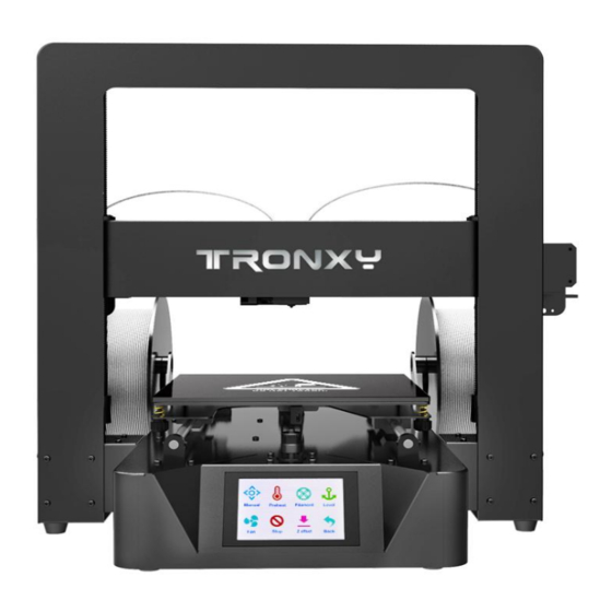
Nozzle PLA.ABS Maxium260°C Ambient 3.5 inches full color touch Display 8-40°C screen temperat Print ambient 0.1mm-0.4mm optional 20-80% Machine slicing Aluminium profiles,sheet TRONXY exclusive slice metal software material software Machine files ≈10.1kg STL.OBJ.DAE.AMF.G-Code weight format Packing operation ≈12.3kg Repetier-Host.Cura weight... - Page 4 2. Machine Introduction 1.Front view Touch screen Gantry bracket The base X axis platform...
-
Page 5: Right View
2.Right view The right material shelf Y polished rod Right feeder FT card slot, USB... -
Page 6: Left View
3. Left view 110V/220V selection port the left material shelf Adjusting nut left feeder... -
Page 7: Back View
4.Back view Power switch Power fuse Power cord connector Two-color extruder Y shaft switch X shaft switch Z shaft switch... -
Page 8: Assembly Parts
3. Product assembly Step 1: assemble the base and the rack (take care to avoid scratching parts when taking and assembling). Assembly parts: The base shelves screwPM4*6 1pcs 1pcs 8个 Take out the bottom rack from the packing box and put it on the shelf, as shown in the figure. - Page 9 Step 2: assemble the filament rack Assembly parts: printer 1pcs left rack parts 1pcs right rack parts 1pcs Loosen the 2 screws on the left and right sides of the cabinet, take 1 piece of left and right material rack as shown in the figure, place it according to the position shown, align the holes, and lock it with 2 screws.
- Page 10 Step 3: feeder assembly Assembly parts: feeder parts printer 1pcs screws PM3*4 6pcs 2pcs 1. Screw through the machine sheet metal hole, align with the screw tooth hole of the feeder component, and then lock it, as shown in the figure. 2.
- Page 11 Step 4: wiring Assembly parts: Power line 1pcs printer(included wiring) 1pcs 1. Insert the male terminal of the shelf 12P wire into the female terminal of the left rear side of the base. 2. 2Motor 6P terminals protruding from the left back side of base, short plug in z1-motor, long plug in e1-motor.
-
Page 12: Operational Guidelines
4. Operational guidelines 1.Enter the main screen of the startup, display the system, tools, and print three main menus. Click on each of the three sub-menus, as shown in the figure.Basic functionality for displaying submenus. 2.Click the system menu and enter it into the system submenu, as shown in the figure: click the return menu and return to the superior menu. - Page 13 2.2Click the machine information and the display is as shown in the figure: the machine brand, ID, version and other information are displayed. Click back menu to return to the superior menu. 2.3Click the Chinese location menu to enter Chinese and English.Click back menu to return to the superior menu.
- Page 14 2.4Click the factory setting and ask if the factory setting is restored.Click to return to restart and restore the factory Settings. 2.5Click the screen correction icon to enter the screen correction and click the cross position for correction. Adjust the screen when the menu is off, save it back.
- Page 15 2.6Click the WIFI menu to enter WIFI parameter setting.Save Settings click on the icon to return. 3.Click the tools menu to enter the machine parameter setting and adjustment. 3.1.1 Click the manual menu to enter the manual adjustment mode.Adjust the motor rotation, E extruder feeding/discharging, XYZ shaft motor moving.ICONS 0.01mm, 0.1mm, 1mm, 10mm,...
- Page 16 After clicking, the dark color is displayed, such as icon 10mm, indicating that each click of motor stroke moves 10mm. Click the icon and the machine returns to the origin.Click back to the parent menu. 3.1.2 Click on the E1 icon, and the E1 icon changes to show E2. Click on the E2 icon againto show E1, as shown in figure E1E2.
- Page 17 and press down the feeder pressing block. As shown in the figure, pass the filaments through the feeder to the material pipe, and click the icon to send the materials to the nozzle to flow the materials.Click the icon motor to stop.Single side feed can not be too long,Avoid plugging the hot material into the cold end of E2.E2 motor filaments feed back and forth.changed to E2,click filaments return,click...
- Page 18 3.5Click the fan icon to enter the fan setting, and turn the fan value 0 OFF, 100 ON, light ON, and light OFF. 3.6.1Click the emergency icon, the machine stops in the current state, and the motor unlocks.When adjusting the gap between the printing platform and the nozzle, use emergency stop to let the extruder slide freely.Gap size, with a piece of A4 paper between the nozzle and the platform sliding resistance, but do not tear the paper is appropriate.The...
- Page 19 4.1Click on the print icon to enter print.The screen displays the files in the machine memory card. Click the arrow to scroll up and down.Click the folder, open the folder, and display the folder contents. 4.2Click on the file and select the file, which is sliced, to enter the file screen.Click the icon to delete the file.Click the icon to enter...
- Page 20 4.2.1Click the icon to stop printing and ask if the filaments should be replaced.To replace the filaments,click YES to replace the filaments as step 3.3 and return to continue printing.Click NO and go back to print. 4.2.2Click the icon to stop printing, and the machine asks if the state is saved.
- Page 21 4.2.3 Click the icon to enter the machine parameter setting change.The initial parameters are set by slicing software. The parameters can be changed in printing, as shown in the figure corresponding to the icon parameters. Click the parameters on the right side of the icon, enter the parameter setting screen, set the parameters, click the icon to save and exit, and click the icon to exit without...
- Page 22 5.Power failure resume to print:When the machine is printing, the machine will automatically save the current status parameters. When the machine is restarted, the screen will show the last interrupt. Will you print from the breakpoint?The option is to print from the breakpoint.Select no or cancel, and the parameters are cleared.
- Page 23 5. Product debugging 1.Z-axis screw debugging: Machine Z axis direction not free or jammed, please loosen the around Z axis motor fixed screw, screw nut screw, screw at the top of the limit bearing fixed screw, polished rod at the top of the screw, the screw loosen to fixed parts can be moved, at the same time synthetic rotating screw, screw, polished rod parallel automatic correction, the motor shaft core, screw nut, shaft core limit bearing shaft core in the same line, locking polished rod at the top of the screw, screw...
- Page 24 Belt adjustment: Y axis belt tension can be adjusted through the connecting screw and nut of the belt passing the wheel.Adjust the tension of X axis belt, loosen the screws of X motor's fixing plate, pull the fixing plate outward, and then lock the screw.If the belt is too loose, it is easy to jump the teeth, which causes the loss of step.
- Page 25 6. FAQ 1.Nozzle plugging material: will the print head heated to above needle dredge nozzle, until manual feeding normal out of 2.Pipe plugging material: the printing head is a straight-through it is easy to cause the pipe blocking material. The pipe should be removed and cleaned.
Need help?
Do you have a question about the X6-2E and is the answer not in the manual?
Questions and answers