
Subscribe to Our Youtube Channel
Related Manuals for Stryker 1089


Summary of Contents for Stryker 1089
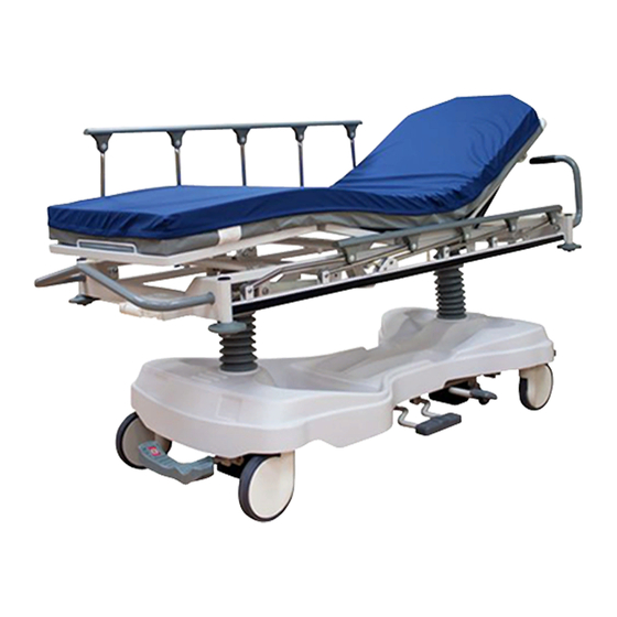
- Page 1 Eye Surgery Stretcher 1089 Maintenance Manual 2013/12 B.0 1089-009-002 REV B www.stryker.com...
-
Page 3: Table Of Contents
International Warranty Clause............www.stryker.com 1089-009-002 REV B... -
Page 4: Symbols And Definitions
NOTE Provides special information to make maintenance easier or important instructions clearer. Return To Table of Contents 1089-009-002 REV B www.stryker.com... -
Page 5: Introduction
Introduction This manual is designed to assist you with the operation of Stryker Model 1089 Eye Surgery Stretcher. Read this manual thoroughly before using the equipment or beginning maintenance on it. To ensure safe operation of this equipment, it is recommended that methods and procedures be established for educating and training staff on the safe operation of this stretcher. -
Page 6: Contact Information
Stryker Medical 3800 E. Centre Avenue Portage, MI 49002 Please have the serial number (A) of your Stryker product available when calling Stryker Customer Service or Technical Support. Include the serial number in all written communication. SERIAL NUMBER LOCATION Return To Table of Contents 1089-009-002 REV B www.stryker.com... -
Page 7: Summary Of Safety Precautions
• The mattress cover must be completely dry before storage or adding linens. Failure to remove excess disinfectant could cause degradation of the cover material. Return To Table of Contents www.stryker.com 1089-009-002 REV B... - Page 8 • Some cleaning products are corrosive in nature and may cause damage to the product if used improperly. If the products suggested above are used to clean Stryker patient handling equipment, measures must be taken to ensure that the stretcher is wiped with a damp cloth soaked in clean water and thoroughly dried following cleaning.
-
Page 9: Setup Procedures
Rotate the head piece in both directions to ensure that it is operating properly. CAUTION Do not modify this stretcher. Modifying the unit can cause unpredictable operation resulting in injury to the patient or operator. Modifying the unit will also void its warranty. Return To Table of Contents www.stryker.com 1089-009-002 REV B... -
Page 10: Cleaning
Some cleaning products are corrosive in nature and may cause damage to the product if used improperly. If the products suggested above are used to clean Stryker patient handling equipment, measures must be taken to ensure that the stretcher is wiped with a damp cloth soaked in clean water and thoroughly dried following cleaning. Failure to properly rinse and dry the stretcher will leave a corrosive residue on the surface of the stretcher, possibly causing premature corrosion of critical components. -
Page 11: Mattress Cleaning
Quaternary Cleaners: identified by ingredients containing the phrase “…yl ammonium chloride” Quat/Isopropyl Cleaners: identified by a quaternary ingredient above plus isopropyl alcohol Phenolic Cleaners: identified by ingredients containing the suffix “-phenol” Chlorine Bleach: known generically as “Sodium Hypochlorite” Return To Table of Contents www.stryker.com 1089-009-002 REV B... - Page 12 Rinse surfaces which have been exposed to the solution with clear water before returning mattress to service. Note: Failure to follow the above directions when using these types of cleaners may void this product’s warranty. Return To Table of Contents 1089-009-002 REV B www.stryker.com...
-
Page 13: Disinfecting The Mattress
Ensure surface has been thoroughly cleaned and dried prior to applying disinfectants. Wipe down the mattress with a clean, dry cloth to remove any excess liquid or disinfectant. Care must be taken to thoroughly rinse and dry covers following disinfection. Return To Table of Contents www.stryker.com 1089-009-002 REV B... -
Page 14: Preventative Maintenance
Preventative Maintenance At a minimum, preventative maintenance should be performed annually. A preventative maintenance program should be established for all Stryker Medical equipment. Preventative maintenance may need to be performed more frequently based on the usage level of the product. -
Page 15: Lubrication Points
Crank Screw Assembly (1069-042-110) With the fowler at 0 degrees, apply Syntech grease (3000-200-719) through the slot and hole in the crank screw assembly (as shown below). Wipe off excess grease. Return To Table of Contents www.stryker.com 1089-009-002 REV B... -
Page 16: Quick Reference Replacement Parts List
The parts and accessories listed on this page are all currently available for purchase. Some of the parts identified on the assembly drawing parts in this manual may not be individually available for purchase. Please call Stryker Customer Service USA at 1-800-327-0770 for availability and pricing. -
Page 17: Service Information
Note: When installing the new brake timing link assembly be sure to reinstall the bushing which may have fallen off during the removal of the old brake timing link assembly. 12. Verify proper operation of the unit before returning it to service. Return To Table of Contents www.stryker.com 1089-009-002 REV B... -
Page 18: Brake Swivel Lock Ring Replacement
Note: When installing the new brake timing link assembly be sure to reinstall the bushing which may have fallen off during the removal of the old brake timing link assembly. 14. Verify proper operation of the unit before returning it to service. Return To Table of Contents 1089-009-002 REV B www.stryker.com... -
Page 19: Brake Timing Link Replacement, Head End Or Foot End
Note: When installing the new brake timing link assembly be sure to reinstall the bushing which may have fallen off during the removal of the old brake timing link assembly. 10. Verify proper operation of the unit before returning it to service. Return To Table of Contents www.stryker.com 1089-009-002 REV B... -
Page 20: Brake Cam Assembly Replacement
Note: When installing the new brake cam assembly, install the bottom slightly first and then push downward and inward to install under the top bearing. 10. Verify proper operation of the unit before returning it to service. Return To Table of Contents 1089-009-002 REV B www.stryker.com... -
Page 21: Brake Rod Replacement
Install the new brake rod and then install the roll pin into the head end timing link arm first. 10. Reverse steps to reinstall. 11. Verify proper operation of the unit before returning it to service. Return To Table of Contents www.stryker.com 1089-009-002 REV B... -
Page 22: Side Control Brake Rod Removal
When reinstalling the brake rod assembly to the base frame, do not exceed 15 ft-lb of torque or damage may occur to the bolts. 11. Verify proper operation before returning the unit to service. Return To Table of Contents 1089-009-002 REV B www.stryker.com... -
Page 23: Fifth Wheel Assembly Replacement
Working from the patients left side, rotate the fifth wheel assembly counter clockwise while lifting the fifth wheel assembly up and out. 10. Reverse steps to reinstall. Torque all bolts to 13 ± 2 ft-lb. 11. Verify proper operation of the unit before returning it to service. Return To Table of Contents www.stryker.com 1089-009-002 REV B... -
Page 24: Jack Replacement, Head End
15. Pump up the litter and apply weight to verify the jacks hold and do not drift. 16. Verify proper operation of the unit before returning it to service. Note: The jack descent rate is set at the factory and adjustment is not recommended. Return To Table of Contents 1089-009-002 REV B www.stryker.com... -
Page 25: Jack Replacement, Foot End
14. Pump up the litter and apply weight to verify the jacks hold and do not drift. 15. Verify proper operation of the unit before returning it to service. Note: The jack descent rate is set at the factory and adjustment is not recommended. Return To Table of Contents www.stryker.com 1089-009-002 REV B... -
Page 26: Release Pedal (Side) Adjustment
Note: If the pedal swivel assembly is threaded too far onto the release rod, the release valve will be partially activated and the jack will drift. Return To Table of Contents 1089-009-002 REV B www.stryker.com... -
Page 27: Litter Removal
With the assistance of another person, lift the litter straight up to remove it from the jack shafts and set it aside. Reverse steps to reinstall the litter. Verify proper operation before returning the unit to service. Return To Table of Contents www.stryker.com 1089-009-002 REV B... -
Page 28: Siderail Latch Adjustment
Hook the extension spring to the eye bolt. Allow the arm board to lower on its own. Repeat steps until the desired counterbalance is achieved. Verify proper operation before returning the unit to service. Return To Table of Contents 1089-009-002 REV B www.stryker.com... -
Page 29: Removal Of Excess Air From The Hydraulic System
Verify that all hydraulic linkages are secure and operating properly. Raise the litter to its highest height. Continue to pump the pedal several times to force the air through the system. Verify proper operation before returning the unit to service. Return To Table of Contents www.stryker.com 1089-009-002 REV B... -
Page 30: Release Pedal Replacement, Foot End
Dislodge the side control release pedal swivels from the studs on the side control release pedal weldment. Remove the foot end pedal release rods. Reverse steps to reinstall the pedal rods. Verify proper operation of the unit before returning it to service. Return To Table of Contents 1089-009-002 REV B www.stryker.com... -
Page 31: Pneumatic Fowler Adjustment
If they do not, repeat step 4. Verify proper operation before returning the unit to service. Figure 12 Return To Table of Contents www.stryker.com 1089-009-002 REV B... -
Page 32: Pneumatic Fowler Release Handle Adjustment
Tighten the two screws on the handle linkage bar and reattach the spring. Check the adjustment of the pneumatic cylinders. See “Pneumatic Fowler Adjustment” on page Verify proper operation before returning the unit to service. Return To Table of Contents 1089-009-002 REV B www.stryker.com... -
Page 33: Pneumatic Cylinder Replacement
Press down on the release pin on the replacement cylinder to extend the cylinder. Reverse steps to install the new cylinder. Check the adjustment of the pneumatic cylinders. See “Pneumatic Fowler Adjustment” on page 10. Verify proper operation before returning the unit to service. Return To Table of Contents www.stryker.com 1089-009-002 REV B... -
Page 34: Warranty
Stryker’s obligation under this warranty is expressly limited to supplying replacement parts and labor for, or replacing, at its option, any product which is, in the sole discretion of Stryker, found to be defective. If requested by Stryker, products or parts for which a warranty claim is made shall be returned prepaid to the factory. Any improper use or any alteration or repair by others in such manner as in Stryker’s judgment affects the product materially and... -
Page 35: Service Contract Programs
* Replacement parts and labor for products under PM contract will be discounted. ** Does not include any disposable items, I.V. poles (except for Stryker HD permanent poles), mattresses, batteries, or damage resulting from abuse. Stryker Medical also offers personalized service contracts. - Page 36 19 ± 4 ft-lb Torque item F to 80 ± 20 in-lb Torque item F to 80 ± 20 in-lb Torque item F to 80 ± 20 in-lb Torque item F to 80 ± 20 in-lb 1089-009-002 REV B www.stryker.com...
- Page 37 Standard brake assembly Torque item E to 40 ± 6 ft-lb Torque item G to 13 ± 2 ft-lb Torque item G to 13 ± 2 ft-lb www.stryker.com 1089-009-002 REV B...
- Page 38 Stepped Flange Bearing 0853–203–135 Brake Rod Assembly (Brake Rod Assembly on page 0853–203–230 Bearing Pivot Support 0853–303–010 Brake Link Assembly, Head End 0853–303–020 Brake Link Assembly, Foot End 0853–401–001 Base Weldment 3001–200–052 Grounding Chain 0014–003–000 Washer 1089-009-002 REV B www.stryker.com...
- Page 39 Rue Ring Cotter 0753–003–015 Brake Rod Nyliner 0853–003–004 Brake Rod Support 0853–003–055 Fifth Wheel Timing Cam Crank Assembly 0853–203–011 Brake Activation Crank 0853–203–137 Brake Rod 0853–206–135 Fifth Wheel Drive Link Assembly 1105–001–335 Label, Brake 1105–001–336 Label, Steer www.stryker.com 1089-009-002 REV B...
- Page 40 50 ±-4 in-lb Torque item F to 80 ± 20 in-lb Torque item F to 80 ± 20 in-lb Torque item F to 80 ± 20 in-lb Torque item F to 80 ± 20 in-lb 1089-009-002 REV B www.stryker.com...
- Page 41 Side control brake assembly to 40 ± 6 ft-lb to 13 ± 2 ft-lb Torque item G to 13 ± 2 ft-lb www.stryker.com 1089-009-002 REV B...
- Page 42 Side control brake assembly Torque item AJ to 13 ± 2 ft-lb 1089-009-002 REV B www.stryker.com...
- Page 43 0853–203–230 Bearing Pivot Support 0853–303–010 Brake Link Assembly, Head End 0853–303–020 Brake Link Assembly, Foot End 0853–401–001 Base Weldment 1105–003–210 Side Control Brake Assembly (Side control brake assembly on page 3001–200–052 Grounding Chain 0014–003–000 Washer www.stryker.com 1089-009-002 REV B...
- Page 44 Brake Rod Nyliner 0753–003–112 Side Control Link 0853–003–004 Brake Rod Support 0853–003–055 Fifth Wheel Timing Cam Crank Assembly 0853–203–011 Brake Activation Crank 0853–203–137 Brake Rod 0853–206–135 Fifth Wheel Drive Link Assembly 1105–001–335 Label, Brake 1105–001–336 Label, Steer 1089-009-002 REV B www.stryker.com...
- Page 45 0026–138–000 Grooved Pin 0026–340–000 Clevis Pin 0027–020–000 Rue Ring Cotter 0753-003–112 Side Control Link 0753–003–117 Rod End Link 0853–003–214 Side Control Shaft Support 1105–001–335 Label, Brake 1105–001–336 Label, Steer 1105–003–319 Side Control Brake Rod 1105–005–154 Pedal www.stryker.com 1089-009-002 REV B...
- Page 46 Bumper color options — set of four 0853–003–085 Rev E (Reference Only) Item Part No. Part Name 0853–003–082 Bumper Bumper Color Set of Four Part Number Cool Grey 0853–003–552 0853–003–554 Navy 0853–003–555 1089-009-002 REV B www.stryker.com...
- Page 47 Compression Wire 0753–103–215 Molded Wheel Assembly 0853–003–032 Label, Caster Brake Pad 0853–003–040 Cam Housing Assembly 0853–003–046 Caster Cover, Right 0853–003–047 Caster Cover, Left 0853–003–048 Caster Cover Plug 0853–203–030 Brake Pad Assembly 0853–303–021 Caster Horn with Bearing Assembly www.stryker.com 1089-009-002 REV B...
- Page 48 Torque item B to 13 ± 2 ft-lb Item Part No. Part Name 0023–288–000 Hex Washer Head Screw 0023–305–000 Hex Washer Head Screw 0753–006–148 Cam Bearing 1105–006–130 Fifth Wheel Assembly (Fifth wheel assembly — 1105–006–130 on page 1089-009-002 REV B www.stryker.com...
- Page 49 0003–083–000 Hex Head Cap Screw 0011–360–000 Washer 0016–035–000 Nylock Hex Nut 0023–288–000 Hex Washer Head Screw 0025–050–000 Dome Head Rivet 0029–007–000 Dual Lock 0029–009–000 Dual Lock 0753–006–074 Torsion Spring 0753–006–075 Torsion Spring 0753–006–097 Drive Shaft Bearing www.stryker.com 1089-009-002 REV B...
- Page 50 Roller Stem 0753–006–198 Drive Pin 0753–006–223 Drive Shaft 0753–006–277 Roller 0853–006–126 Fifth Wheel Bracket 0853–006–131 Fifth Wheel Weldment 0853–006–227 Return Spring Hook 0853–010–045 Hood Standoff 1210–001–147 Wheel 0023–160–000 Hex Washer Head Screw 0853–006–011 Link Stop Plate 1089-009-002 REV B www.stryker.com...
- Page 51 13 ± 3 ft-lb Torque item A to 13 ± 3 ft-lb Torque item A to 13 ± 3 ft-lb Item Part No. Part Name 0023–288–000 Hex Washer Head Screw 0753–002–001 Constant Descent Jack Assembly 0853–010–07 Reservoir Clamp www.stryker.com 1089-009-002 REV B...
- Page 52 Trend limiter–1069–020–010 Rev A (Reference Only) Item Part No. Part Name 1040–010–027 Trend Limiter 1089-009-002 REV B www.stryker.com...
- Page 53 Dual-sided hydraulics assembly 1105–005–500 Rev C (Reference Only) Torque item C to 13 ± 2 ft-lb www.stryker.com 1089-009-002 REV B...
- Page 54 - 1105–004–201 on page 55 1105–005–035 Pump Connecting Tube Weldment 1105–005–075 Pump Pedal Link 1105–005–285 Pump Pedal Assembly, Head End (Pump pedal assembly, head end – 1105–005–285 on page 56 0853–204–014 Release Rod, Head End 1089-009-002 REV B www.stryker.com...
- Page 55 Lowering pedal assembly - 1105–004–201 Rev A (Reference Only) Item Part No. Part Name 0025–133–000 Dome Head Rivet 0753–004–029 Release Pedal Standoff 0853–004–320 Release Pedal Support 1105–004–004 Release Pedal Weldment 1105–201–127 Short Uni-Pedal www.stryker.com 1089-009-002 REV B...
- Page 56 Pump pedal assembly, head end – 1105–005–285 Rev B (Reference Only) Item Part No. Part Name 0026–343–000 Groove Pin 0715–001–140 Vinyl Tube 1105–105–180 Pump Pedal Weldment, Head End 1105–201–126 Pump Pedal 1089-009-002 REV B www.stryker.com...
- Page 57 Three-sided hydraulics assembly 1105–005–510 Rev D (Reference Only) to 13 ± 2 ft-lb www.stryker.com 1089-009-002 REV B...
- Page 58 Pump Pedal Spring Return Bracket 1105–004–223 Release Pedal Assembly, Foot End (Release pedal assembly, foot end on page 1105–005–075 Pump Pedal Link 1105–005–273 Pump Pedal Assembly, Foot End (Pump pedal assembly, foot end – 1105–005–273 on page 1089-009-002 REV B www.stryker.com...
- Page 59 Snap-In Nyliner 0753–004–028 Release Pedal Return Spring, Foot 0853–004–138 Release Rod, Foot End 0853–004–139 Release Rod, Head End 1105–004–144 Release Pedal, Left, Foot End 1105–004–145 Release Pedal, Right, Foot End 1105–004–422 Release Pedal Mounting Bracket, Foot End www.stryker.com 1089-009-002 REV B...
- Page 60 Pump pedal assembly, foot end – 1105–005–273 Rev A (Reference Only) Item Part No. Part Name 0026–343–000 Groove Pin 0715–001–140 Clear Vinyl Tubing 1105–005–171 Pump Pedal Weldment, Foot End 1105–201–126 Plastic Pump Pedal 1089-009-002 REV B www.stryker.com...
- Page 61 Base labels — standard brakes, side control hydraulics 1089–010–100 Rev A (Reference Only) Item Part No. Part Name 0747–001–035 Standard Hood 0747–010–134 Dipped Bellows 0946–201–060 Label, Stryker Logo 0753–010–351 Label, Brake/Steer, Foot End 0853–010–355 Label, Lift/Lower, Left 0853–010–354 Label, Lift/Lower, Right www.stryker.com...
- Page 62 Part Number Department Quantity 1105–023–004 Emergency 1105–023–005 Transport 1105–023–006 Surgery 1105–023–007 PACU 1105–023–008 Endoscopy 1105–023–009 Radiology 1105–023–010 Cath Lab 1105–023–011 Ambulatory Surgery 1105–023–012 Same Day Surgery 1105–023–013 Maternity 1105–023–014 GI Lab 1105–023–015 Ultrasound 1105–023–016 Stryker Demo 1089-009-002 REV B www.stryker.com...
- Page 63 Base labels — standard brakes, foot end / side control hydraulics 1089–010–200 Rev A (Reference Only) Item Part No. Part Name 0747–001–034 Four-Sided Brakes Hood 0747–010–134 Dipped Bellows 0946–201–060 Label, Stryker Logo 0853–010–018 Label, Brake/Steer, Right 0853–010–019 Label, Brake/Steer, Left 0753–010–351...
- Page 64 Part Number Department Quantity 1105–023–004 Emergency 1105–023–005 Transport 1105–023–006 Surgery 1105–023–007 PACU 1105–023–008 Endoscopy 1105–023–009 Radiology 1105–023–010 Cath Lab 1105–023–011 Ambulatory Surgery 1105–023–012 Same Day Surgery 1105–023–013 Maternity 1105–023–014 GI Lab 1105–023–015 Ultrasound 1105–023–016 Stryker Demo 1089-009-002 REV B www.stryker.com...
- Page 65 Base labels — foot end / side brakes, side control hydraulics 1089–010–300 Rev A (Reference Only) Item Part No. Part Name 0747–001–037 Three-Sided Hydraulics Hood 0747–010–134 Dipped Bellows 0853–010–052 Label, Pump Pedal, Foot End 0753–010–053 Label, Lowering Pedal, Foot End 0946–201–060...
- Page 66 Part Number Department Quantity 1105–023–004 Emergency 1105–023–005 Transport 1105–023–006 Surgery 1105–023–007 PACU 1105–023–008 Endoscopy 1105–023–009 Radiology 1105–023–010 Cath Lab 1105–023–011 Ambulatory Surgery 1105–023–012 Same Day Surgery 1105–023–013 Maternity 1105–023–014 GI Lab 1105–023–015 Ultrasound 1105–023–016 Stryker Demo 1089-009-002 REV B www.stryker.com...
- Page 67 Base labels — foot end / side brakes, side control hydraulics 1089–010–400 Rev A (Reference Only) Item Part No. Part Name 0747–001–036 Four-Sided Brakes and Three-Sided Hydraulics Hood 0747–010–134 Dipped Bellows 0853–010–052 Label, Pump Pedal, Foot End 0753–010–053 Label, Lowering Pedal, Foot End 0946–201–060...
- Page 68 Part Number Department Quantity 1105–023–004 Emergency 1105–023–005 Transport 1105–023–006 Surgery 1105–023–007 PACU 1105–023–008 Endoscopy 1105–023–009 Radiology 1105–023–010 Cath Lab 1105–023–011 Ambulatory Surgery 1105–023–012 Same Day Surgery 1105–023–013 Maternity 1105–023–014 GI Lab 1105–023–015 Ultrasound 1105–023–016 Stryker Demo 1089-009-002 REV B www.stryker.com...
- Page 69 Litter assembly 1089–030–110 Rev A (Reference Only) www.stryker.com 1089-009-002 REV B...
- Page 70 Litter assembly 1089-009-002 REV B www.stryker.com...
- Page 71 Rectangular Hole Plug 1068–020–038 Bumper Channel 1089–030–130 Jack Support Assembly, Head End (Jack support assembly, head end on page 1089–030–150 Litter Frame Weldment 1089–032–210 Jack Support Assembly, Foot End (Jack support assembly, foot end on page www.stryker.com 1089-009-002 REV B...
- Page 72 Jack support assembly, foot end 1089–032–210 Rev A (Reference Only) Item Part No. Part Name 0003–040–000 Hex Head Cap Screw 0016–036–000 Nylock Hex Nut 0023–288–000 Hex Washer Head Screw 0044–029–000 Double-Sided Foam Tape .5 ft 1037–010–029 Support Tube 0919–030–028 Rack Glide 0938–001–401...
- Page 73 Jack support assembly, head end 1089–030–130 Rev A (Reference Only) Item Part No. Part Name 0011–360–000 Washer 0023–288–000 Hex Washer Head Screw 1037–010–029 Support Tube 1069–030–120 Jack Mount Weldment, Left 1069–030–125 Jack Mount Weldment, Right www.stryker.com 1089-009-002 REV B...
- Page 74 Dual articulating pneumatic fowler – 1089–132–210 Rev B (Reference Only) 1089-009-002 REV B www.stryker.com...
- Page 75 Dual articulating pneumatic fowler – 1089–132–210 Item Part No. Part Name 1069–031–011 Shoulder Rivet 1069–031–012 Barrel Nut 1069–031–013 Hole Plug 1069–031–031 Handle Adjustment Link, Short 1069–031–032 Handle Adjustment Link, Long 1089–031–036 Cylinder Mounting Box 1069–031–041 Handle Pivot Bracket, Left 1069–031–046 Handle Pivot Bracket, Right 1069–031–060...
- Page 76 Dual articulating pneumatic fowler – 1089–132–210 Item Part No. Part Name 0007–042–000 Truss Head Machine Screw 0007–050–000 Truss Head Machine Screw 0007–062–000 Truss Head Machine Screw 0013–018–000 External Tooth Lock Washer 0015–003–000 Hex Nut 0015–060–000 Nylock Hex Nut 0016–036–000 Nylock Hex Nut 0016–028–000...
- Page 77 Dual articulating crank fowler – 1089–142–250 Rev B (Reference Only) Item Part No. Part Name 0004–054–000 Button Head Cap Screw 0007–042–000 Truss Head Machine Screw 0011–179–000 Washer 0016–036–000 Nylock Hex Nut 0025–050–000 Rivet 1069–031–012 Barrel Nut 1069–031–013 Hole Plug 1069–032–055 Fowler Skin 1089–132–250...
- Page 78 Dual articulating head piece – 1069–133–020 Rev D (Reference Only) 1089-009-002 REV B www.stryker.com...
- Page 79 Dual articulating head piece – 1069–133–020 Item Part No. Part Name 0007–080–000 Truss Head Machine Screw 0011–304–000 Washer 0016–123–000 Hex Nut 0037–200–000 Vinyl Cap 0038–474–000 Compression Spring 0052–086–000 Nyliner 0052–815–000 Nyliner 0058–056–000 Edge Trim www.stryker.com 1089-009-002 REV B...
- Page 80 Headpiece Cover 1069–133–076 Gear Housing 1069–133–083 Head Shaft 1069–133–084 Neck Shaft 1069–133–085 Neck Spacer 1069–133–088 Head Spacer 1069–133–100 Link Weldment 1069–133–110 Handle Weldment, Right 1069–133–115 Handle Weldment, Left 7900–001–102 Velcro Pile .71 ft 1069–133–121 Handle Torsion Spring 1089-009-002 REV B www.stryker.com...
- Page 81 Crank fowler assembly 1089–042–120 Rev B (Reference Only) Item Part No. Part Name 0003–078–000 Hex Head Cap Screw 0008–027–000 Shoulder Bolt 0016–028–000 Nylock Nut 0946–001–064 Label, Fowler 1089–034–015 Mounting Bracket Assembly 1066–033–068 Sleeve 1089–042–110 Crank Screw Assembly 0014–019–000 Flat Washer www.stryker.com...
- Page 82 Crank screw assembly – 1089–042–110 Rev C (Reference Only) 1089-009-002 REV B www.stryker.com...
- Page 83 Crank screw assembly – 1089–042–110 Item Part No. Part Name 1089–042–023 Crank Arm Link 1089–001–016 Crank Handle 0946–033–018 Crank Disc 0938–001–177 Knob 0016–005–000 Conelock Nut 0378–024–029 Shoulder Bolt 0946–033–035 Fowler Screw 0026–014–000 Roll Pin 0081–174–000 Thrust Washer 0938–001–175 Bearing Assembly 0081–176–000...
- Page 84 Stationary foot section assemby 1089–024–004 Rev A (Reference Only) Item Part No. Part Name 0003–073–000 Hex Head Cap Screw 0014–003–000 Washer 0016–028–000 Hex Nut 0025–101–000 Rivet 1010–032–060 Pivot Bolt 1089–044–050 Stationary Foot Weldment 1089–019–001 Steel Foot Section Skin 7900–001–102 Velcro Pile 1089-009-002 REV B www.stryker.com...
- Page 85 Gatch assembly 1089–040–110 Rev B (Reference Only) www.stryker.com 1089-009-002 REV B...
- Page 86 Pivot Bolt 1089–034–015 Mounting Bracket Assembly 1089–041–010 Foot and Thigh Subassembly 1089–046–010 Knee Gatch Crank Screw Assembly (Gatch crank screw assembly – 1089–046–010 on page 1510–034–190 Slider Pad 0748–034–194 Calf Stand Rest 7900–001–102 Velcro Pile .33 ft 1089-009-002 REV B...
- Page 87 Foot end thigh section subassemby 1089–041–010 Rev B (Reference Only) Item Part No. Part Name 7900–001–102 Velcro ADH Pile 1.92 ft 0014–003–000 Washer 0014–021–000 Flat Washer 0016–028–000 Hex Nut 0025–079–000 Dome Head Rivet 0025–101–000 Dome Head Rivet 0027–007–000 Extended Prong Cotter Pin 1010–032–060...
- Page 88 Gatch crank screw assembly – 1089–046–010 Rev B (Reference Only) Item Part No. Part Name 0946–033–018 Crank Disc 1089–001–016 Crank Handle 0026–045–000 Roll Pin 0026–014–000 Roll Pin 0081–176–000 Thrust Washer 0081–175–000 Thrust Bearing 0081–174–000 Thrust Washer 0938–001–175 Bearing Assembly 0938–001–177 Knob 0378–024–029...
- Page 89 Siderail to litter assembly, two position siderails 1089–020–010 Rev A (Reference Only) Item Part No. Part Name 0004–135–000 Button Head Cap Screw 0004–515–000 Button Head Cap Screw 0011–002–000 Light Flat Washer 0016–028–000 Fiberlock Hex Nut 0021–104–000 Set Screw 0038–220–000 Compression Spring 0721–026–066...
- Page 90 Two–position siderail assembly, right – 1068–020–015 Rev- (Reference Only) Item Part No. Part Name 1010–026–015 Top Rail 1010–026–083 Upright 1010–026–084 Bent Upright 1010–026–082 Sleeve Bearing 0025–106–000 Semi-Tubular Rivet 1010–026–010 Round Hole Plug 1010–026–085 Latch Upright Assembly 1010–026–012 Bent Spindle Rest 1089-009-002 REV B www.stryker.com...
- Page 91 Two–position siderail assembly, left – 1068–020–017 Rev- (Reference Only) Item Part No. Part Name 1010–026–015 Top Rail 1010–026–083 Upright 1010–026–084 Bent Upright 1010–026–082 Sleeve Bearing 0025–106–000 Semi-Tubular Rivet 1010–026–010 Round Hole Plug 1010–026–085 Latch Upright Assembly 1010–026–012 Bent Spindle Rest www.stryker.com 1089-009-002 REV B...
- Page 92 Siderail to litter assembly, optional three-position siderail 1089–021–010 Rev A (Reference Only) Item Part No. Part Name 1066–026–015 Siderail Assembly, Right (Three– postion siderail assembly, right – 1066–026–015 on page 1066–026–017 Siderail Assembly, Left (Three– position siderail assembly, left –...
- Page 93 Three–postion siderail assembly, right – 1066–026–015 Rev B (Reference Only) Item Part No. Part Name 1010–026–015 Top Rail 1010–026–083 Upright 1010–026–084 Bent Upright 1010–026–082 Sleeve Bearing 0025–106–000 Semi-Tubular Rivet 1010–026–010 Hole Plug 1066–026–027 Latch Upright Assembly 1010–026–012 Bent Spindle Rest www.stryker.com 1089-009-002 REV B...
- Page 94 Three–position siderail assembly, left – 1066–026–017 Rev B (Reference Only) Item Part No. Part Name 1010–026–015 Top Rail 1010–026–083 Upright 1010–026–084 Bent Upright 1010–026–082 Sleeve Bearing 0025–106–000 Semi-Tubular Rivet 1010–026–010 Hole Plug 1066–026–027 Latch Upright Assembly 1010–026–012 Bent Spindle Rest 1089-009-002 REV B www.stryker.com...
- Page 95 Optional surgery accessory rail – 1089–266–000 1089–266–010 Rev A (Reference Only) Item Part No. Part Name 0003–047–000 Hex Head Cap Screw 0004–495–000 Socket Head Cap Screw 0016–028–000 Fiberlock Hex Nut 1068–066–042 Optional Bar/Rail 1089–266–050 Optional Bar/Weldment Mounting Bracket www.stryker.com 1089-009-002 REV B...
- Page 96 Drape Support Weldment 1068–068–043 Oxygen Tube Cap 1068–268–042 Oxygen Hose Receptacle 1068–068–041 Oxygen Supply Line 1068–090–068 Label, Specification 1066–085–013 Goose Neck 1068–168–015 Oxygen Latch 0026–172–000 Roll Pin 0014–007–000 Flat Washer 0011–063–000 Washer 0030–067–000 Grommet 0052–324–000 Spacer 1089-009-002 REV B www.stryker.com...
- Page 97 0028–104–000 Retaining Ring 0390–011–012 Foam Pad 1060–001–152 Disc 1060–001–154 Split Ring 1060–001–155 Ball Post 1060–001–159 Leg Support Bar 1068–056–013 Armboard Cover 1068–056–015 Armboard 1068–056–016 Restraint Strap Assembly 8812–670–000 7900–001–102 Velcro Pile 4 in. 1068–054–010 Direct Clamp www.stryker.com 1089-009-002 REV B...
- Page 98 Button Head Cap Screw 0024–044–000 T-Handle 0028–104–000 Retaining Ring 0390–011–012 Foam Pad 1060–001–152 Disc 1060–001–154 Split Ring 1060–001–155 Ball Post 1060–001–159 Leg Support Bar 1068–056–013 Armboard Cover 1068–056–015 Armboard 1068–056–016 Restraint Strap Assembly 8812–670–000 7900–001–102 Velcro Pile 4 in. 1089-009-002 REV B www.stryker.com...
- Page 99 Part Name 0002–044–000 Round Head Machine Screw 0025–055–000 Blind Hole Rivet 0029–008–000 Dual Lock 0029–010–000 Dual Lock 1105–145–201 Label, Defibrillator Tray 1105–045–204 Tray Support 1105–045–207 Tray 0785–045–208 Bayonet 1105–045–210 Defibrillator Tray Frame Weldment 1010–050–021 Long Strap www.stryker.com 1089-009-002 REV B...
- Page 100 1105–145–401 Label, Foot Extender/Defibrillator Tray 0785–045–405 Cushion 0785–045–410 Base Mounting Weldment 0785–045–420 Pivot Weldment Frame 0747–045–430 Tray Assembly 0785–045–450 Knob 1010–050–021 Long Strap 1010–050–242 Pin Lock 1010–050–250 Lock Adjuster 1010–050–248 Lower Pin Lock 0721–031–065 Hole Plug 1089-009-002 REV B www.stryker.com...
- Page 101 Footboard / chart holder – 1105–045–500 Rev B (Reference Only) Item Part No. Part Name 1105–145–501 Label, Footboard 1105–045–511 Chart Holder Thermoform 1105–045–512 Footboard, Back 1105–045–513 Footboard, Front 1105–045–514 Small Standoff 1105–045–515 Large Standoff 0946–029–010 Support www.stryker.com 1089-009-002 REV B...
- Page 102 Pre–op / post–op head pads – 1089–160–010 Rev A (Reference Only) Item Part No. Part Name 0007–080–000 Truss Head Machine Screw 0004–135–000 Button Head Cap Screw 0015–004–000 Hex Nut 0016–005–000 Conelock Nut 0021–119–000 Set Screw 1089–060–025 Headpiece, Right 1089–060–035 Headpiece, Left 1069–060–060...
- Page 103 Removable IV pole assembly – 0390–025–000 Rev K (Reference Only) Item Part No. Part Name 0390–003–056 Knob 0390–003–053 Double IV Assembly 0393–003–043 Tube Assembly 0004–496–000 Socket Head Cap Screw 0390–125–011 Label, IV Pole, Removable www.stryker.com 1089-009-002 REV B...
- Page 104 Optional two–stage permanent IV pole, foot end – 1089–080– Rev B (Reference Only) Item Part No. Part Name 0003–050–000 Hex Head Cap Screw 0004–199–000 Button Head Cap Screw 0016–036–000 Fiberlock Hex Nut 0016–028–000 Fiberlock Hex Nut 1001–159–042 Plug 1089–259–111 IV Pivot Weldment 1211–210–010...
- Page 105 Optional three–stage permanent IV pole, foot end – 1089–062– Rev B (Reference Only) Item Part No. Part Name 1211–211–010 Three-Stage IV Pole Assembly 1089–259–111 IV Pivot Weldment 0004–199–000 Button Head Cap Screw 0016–036–000 Nylock Hex Nut 1001–159–042 Plug www.stryker.com 1089-009-002 REV B...
- Page 106 Optional foot end push handle, bolt on 1089–700–010 Rev A (Reference Only) Item Part No. Part Name 0016–035–000 Hex Nut 0003–078–000 Hex Head Cap Screw 0016–028–000 Hex Nut 1089–400–142 Bumper 1089–700–055 Bolt On Push Handle Socket, Left 1089–700–056 Bolt on Push Handle Socket, Right 1211–351–010...
- Page 107 Push handle assembly 1211–351–010 Rev A (Reference Only) Item Part No. Part Name 1010–354–024 PUP Stop Link 1211–151–018 PUP Sleeve Assembly 0026–118–000 Spring Pin www.stryker.com 1089-009-002 REV B...
- Page 108 Optional upright bottle holder assembly — 1089–030–000 Rev B (Reference Only) MAX. 40 lbs. (18 kg) 1089-030-000 BOTTLE HOLDER Portage, MI 49002-5826 Made In USA Item Part No. Part Name 1089–030–011 Upright Bottle Holder 0027–012–000 Hair Pin Cotter 0741–030–024 Nylon Standoff 1089–030–017...
- Page 109 Optional oxygen bottle retainer assembly – 1037–010–090 1037–010–095 Rev A (Reference Only) Item Part No. Part Name 0747–010–091 Oxygen Bottle Retainer Hoop 1040–010–092 Scrulock Assembly www.stryker.com 1089-009-002 REV B...
- Page 110 Ma de in U.S .A. Item Part No. Part Name 1105–145–701 Label, Serving Tray 0785–045–704 Plastite High Torque Fastener System 1105–045–705 Serving Tray Top 0785–045–706 Serving Tray Pinion 1105–045–710 Serving Tray Slider 1105–045–715 Serving Tray Cover 1089-009-002 REV B www.stryker.com...
- Page 111 Rev B (Reference Only) 1105 -045-800 a de in U.S .A. Item Part No. Part Name 0025–079–000 Dome Head Rivet 0025–133–000 Dome Head Rivet 1105–145–801 Label, Serving Tray Holder 1105–045–805 Footboard 1105–045–810 Footboard Support Weldment 0946–001–155 Bumper www.stryker.com 1089-009-002 REV B...
- Page 112 Female Insert Knob 0004–371–000 Socket Head Cap Screw 1068–050–055 Support Bar Wrist Rest Weldment 1068–250–041 Wrist Rest Wedge Bolt 1068–250–042 Wrist Rest Lock Wedge 1068–250–050 Base Tube Weldment 1068–252–055 Support Bar Wrist Rest Casting 1068–290–050 Label, Wrist Rest 1089-009-002 REV B www.stryker.com...
- Page 113 Female Insert Knob 0004–371–000 Socket Head Cap Screw 1068–051–050 Temporal Tube Weldment 1068–250–041 Wrist Rest Wedge Bolt 1068–250–042 Wrist Rest Lock Wedge 1068–250–050 Base Tube Weldment 1068–252–055 Support Bar Wrist Rest Casting 1068–290–051 Label, Wrist Rest www.stryker.com 1089-009-002 REV B...
- Page 114 Mattresses – 1069–026–070, 1069–026–090 Rev D (Reference Only) 3” x 26”, Enhanced Comfort, Dual Articulation, 4 x 26", Ultra Comfort, Dual Articulation, 1069–026–070 1069–026–090 1089-009-002 REV B www.stryker.com...
- Page 115 Optional siderail pad set – 1010–052–000 Rev A (Reference Only) www.stryker.com 1089-009-002 REV B...
- Page 116 Headpiece assembly, right – 1089–060–025 Rev A (Reference Only) Item Part No. Part Name 0038–162–000 Pin Slide Spring 1089–060–040 Tube Weldment, Right 1069–060–090 Label, Head Extension 1069–060–140 Slider Pin 1069–060–142 Spring Spacer 1069–060–145 Cam Pin 1069–060–012 Latch Knob 1068–260–091 Label, Latch Release 7900–001–102...
- Page 117 Headpiece assembly, left – 1089–060–035 Rev A (Reference Only) Item Part No. Part Name 0038–162–000 Pin Slide Spring 1089–060–050 Tube Weldment, Left 1069–060–090 Label, Head Extension 1069–060–140 Slider Pin 1069–060–142 Spring Spacer 1069–060–145 Cam Pin 1069–060–012 Latch Knob 1068–260–091 Label, Latch Release 7900–001–102...
- Page 118 Latch bracket assembly, left – 1089–060–225 Rev A (Reference Only) Item Part No. Part Name 0004–325–000 Button Head Cap Screw 1069–060–222 Latch Pin 1089–060–226 Latch Pin Support Bracket 1089-009-002 REV B www.stryker.com...
- Page 119 Latch bracket assembly, right – 1089–060–220 Rev A (Reference Only) Item Part No. Part Name 0004–325–000 Button Head Cap Screw 1089–060–221 Latch Pin Support Bracket 1069–060–222 Latch Pin www.stryker.com 1089-009-002 REV B...
- Page 120 Ankle restraint strap – 0946–043–001 Rev D (Reference Only) 1089-009-002 REV B www.stryker.com...
- Page 121 Wrist restraint strap – 0946–044–000 Rev A (Reference Only) 0946-044-001 a de in U.S .A. 0946–044–001 Rev F (Reference Only) Wrist Restraining Strap www.stryker.com 1089-009-002 REV B...
- Page 122 Chest restraint strap (2 piece) – 1010–058–000 Rev C 0390-019-001 Ma de in U.S .A. 0390-019-002 Ma de in U.S .A. 0390–019–001 Rev M (Reference Only) Restraining Strap, Long 0390–019–002 Rev L (reference Only) Restraining Strap, Short 1089-009-002 REV B www.stryker.com...
- Page 123 Body restraint strap – 0390–019–000 Rev B (Reference Only) 0390-019-001 Ma de in U.S .A. 0390-019-002 Ma de in U.S .A. 0390–019–001 Rev M (Reference Only) Restraining Strap, Long 0390–019–002 Rev L (Reference Only) Restraining Strap, Short www.stryker.com 1089-009-002 REV B...
- Page 124 Full restraint strap package – 1010–077–000 Rev A (Reference Only) 0390–019–000 Rev B (Reference Only) Body Restraint 0946–043–001 Rev B (Reference Only) Ankle Restraint Strap Assembly 0946–047–000 Rev B (Reference Only) Wrist Restraint 1010–058–000 Rev C (Reference Only) Chest Restraint 1089-009-002 REV B www.stryker.com...
- Page 126 Stryker Medical 3800 E. Centre Ave. Portage, Michigan 49002 Stryker EMEA RA/QA Director ZAC - Avenue de Satolas Green 69881 MEYZIEU Cedex France 2013/12 1089-009-002 REV B www.stryker.com...
Need help?
Do you have a question about the 1089 and is the answer not in the manual?
Questions and answers