Table of Contents
Advertisement
Quick Links
Declaration of Conformity
According to 47 CFR, Parts 2 and 15 of the FCC Rules
The following designated product:
EQUIPMENT: MAINBOARD
MODEL NO.: 5SSV
is a Class B digital device that complies with 47 CFR Parts 2 and 15 of the FCC Rules.
Operation is subject to the following two conditions:
1. This device may not cause harmful interference.
2. This device must accept any interference received, including interference
that may cause undesired operation.
This declaration is given to the manufacturer:
CHAINTECH COMPUTER U.S., INC
509 Valley Way, Milpitas, CA 95035, U.S.A.
Tel: 1-408-935-6988
Fax: 1-408-935-6989
Chaintech President: Raff Tung
Signature:
Advertisement
Table of Contents

Related Manuals for CHAINTECH CT-5SSV


Summary of Contents for CHAINTECH CT-5SSV
- Page 1 1. This device may not cause harmful interference. 2. This device must accept any interference received, including interference that may cause undesired operation. This declaration is given to the manufacturer: CHAINTECH COMPUTER U.S., INC 509 Valley Way, Milpitas, CA 95035, U.S.A. Tel: 1-408-935-6988 Fax: 1-408-935-6989...
- Page 2 Federal Communications Commission Statement This device complies with FCC Rules Part 15. Operation is subject to the following two conditions: This device may not cause harmful interference This device must accept any interference received, including interference that may cause undesired operation. This equipment has been tested and found to comply with the limits for a Class B digital device, pursuant to Part 15 of the FCC Rules.
-
Page 3: Table Of Contents
T T T T T ab le of Contents le of Contents ab le of Contents le of Contents le of Contents Chapter 1 Introduction ................1 Product Specifications ............1 Package Contents ..............4 Mainboard Layout ..............5 Connector and Jumper Reference Chart ....... 5 Chapter 2 Hardware Setup .............. - Page 4 Feature Explanations Software Power-off Control ..............12 Over-ride Power Button ................ 13 Blinking LED in Suspend Mode ............13 Power On By Modem ..............12/35 Power On By Alarm ................35 Power On By Keyboard ................ 35 Poly-fuse Over Current Protection ............18 Appendices Appendix I On Board I/O Addresses &...
-
Page 5: Chapter 1 Introduction
Introduction Chapter 1 Introduction 1-1 Product Specifications Processor ® - Supports up to 200 MHz Intel Pentium processors and up to 233MHz ® Pentium processors with MMX technology - Supports Cyrix/IBM 6x86MX PR166 ~PR233 and up to 380 MHz MII processors - Supports AMD K6 166 MHz~266 MHz processors, K6-2 ,K6-2 CXT and K6-III up to 450 MHz processors... - Page 6 Chapter 1 Two Ultra DMA-66 PCI IDE Ports - Supports up to PIO Mode 4, Multi-word Mode 4 and Ultra DMA-33/66 timings - Complete Bus Mastering software drivers for all well known multi-task operating systems Embedded Ultra I/O - ITE 8661 I/O chip - One Parallel (SPP/ECP/EPP) and one Serial (16550A compliant) ports - One floppy disk drive connector supports up to 2.88MB, Japanese 3-Mode, and 1Mbps transfer rates...
- Page 7 Introduction Board Dimensions - Micro-ATX form factor, 244mm x220mm, 4 Layers - Six mounting holes Advanced Management Features - Software power off control, Over-ride power button, Power-on by modem, Power-on by keyboard, Power-on by alarm,Power failure recovery, Blinking LED in Suspend etc. - Integrated LDCM compliant System Monitor Hardware for electrical security - Poly-fuse over-current protection for USB and keyboard - Supports PC/PCI to Creative S-link...
-
Page 8: Package Contents
Chapter 1 1-2 Package Contents 1-2 Package Contents 1-2 Package Contents 1-2 Package Contents 1-2 Package Contents This product comes with the following components: One mainboard One 40-pin Ultra DMA-66 IDE connector ribbon cable (Figure 1-1) * Color coded connection for UDMA/66 cable Blue to mainboard, Ground in blue, Gray to Master and Black to slave One 34-pin floppy disk drive ribbon cable (Figure 1-2a) or (Figure 1-2b) One plastic stub for standard ATX installation (Figure 1-3) -
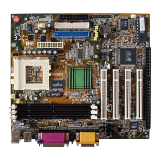
Page 9: Mainboard Layout
Introduction 1-3 Mainboard Layout 1-3 Mainboard Layout 1-3 Mainboard Layout 1-3 Mainboard Layout 1-3 Mainboard Layout B ack P anel I/O C onnector PC B U S B 2 V G A 1 C O M 1 K /B U S B 1 G a m e P rin te r M ou se... - Page 10 Chapter 1 Memo Memo Memo Memo Memo...
-
Page 11: Chapter 2 Hardware Setup
Hardware Setup Chapter 2 Chapter 2 Chapter 2 Chapter 2 Chapter 2 Hardware Setup Hardware Setup Hardware Setup Hardware Setup Hardware Setup If your mainboard has already been installed in your computer you may still need to refer to this chapter if you plan to upgrade your system's hardware. Be sure to disconnect the power cable from the power source before performing any work on your mainboard, i. -
Page 12: Installing A Pga Type Cpu In A Zif Socket
Chapter 2 2-2 Installing a PGA type CPU in a ZIF Socket The Intel Socket 7, designed for the Pentium processor, has been incorporated as a standard mainboard specification and is compatible with AMD and Cyrix CPUs. To insert your CPU into Socket 7 please do the following: 1. -
Page 13: Cpu Jumper Configuration
Hardware Setup 2-3 CPU Jumper Configuration Frequency Configuration Frequency Configuration Frequency Configuration Frequency Configuration Frequency Configuration If you install a CPU on this mainboard, you must set for System Frequency JP11, 13~15 for CPU Bus Frequency Ratio. See Figure 2-4 CPU/System Frequency JP4~6 Jumper Settings. - Page 14 Chapter 2 Overclocking Operating a CPU at a higher frequency than its specification allows is called overclocking. If the CPU frequency is set at a higher frequency than its specification allows, it may or may not run at that freqency, depending on the quality of your CPU and the extent to which the frequency has been overset.
- Page 15 Hardware Setup CPU Power Voltage System freq. Freq. ratio CPU-type Core JP16~20 JP11, 13~15 Speed rate JP4~ I/O Vcc P54C-166 x2.5 P54C-200 Pentium x2.5 w/MMX Intel @166MHz Pentium w/MMX @200MHz Pentium x3.5 w/MMX @233MHz 6x86L-PR166 @133MHz 6x86L-PR200 @150MHz 6x86MX-PR166 6x86MX-PR200 x2.5 Cyrix 6x86MX-PR200...
-
Page 16: Connector And Jumper Settings
Chapter 2 2-4 Connector and Jumper Settings Connectors are used to link the system board with other parts of the system, including the power supply, the keyboard, and the various controllers on the front panel of the system case. The power supply connector is the last connection to be made while installing a mainboard. - Page 17 Hardware Setup Front Panel Connector Set (J5) A through G A. Over-ride Power Button Connector The power button on the ATX chassis can be used as a normal power switch as well as a button to activate Advanced Power Management Suspend mode. This mode is used for saving electricity when the computer is not in use for long periods of time.
- Page 18 Chapter 2 C. Green Switch/Green LED Connector Some ATX cases provide a Green switch which is used to put the system in Suspend mode. In Suspend mode, the power supply to the system is reduced to a trickle, the CPU clock is stopped, and the CPU core is in its minimum power state.
- Page 19 Hardware Setup Infrared Connector If you enable the IR Address Select in BIOS's Integrated Peripherals menu the IR port will let you select the IRQ and IR Mode to support IR functions. (See section 3-8) CPU/System Cooling Fan Connectors These added connectors allow the fan to draw their power from the mainboard instead of the disk drive connector.
- Page 20 Chapter 2 Modem Telephony Connector (J1) Modem Telephony Connector (J1) Modem Telephony Connector (J1) Modem Telephony Connector (J1) Modem Telephony Connector (J1) This connector must be connected to the cable from the voice modem card to support modem audio signals. G ND G ND M O NO IN...
- Page 21 Hardware Setup WOL (Wake-on-LAN) Connector (J4) Enable the Wake Up On LAN selection in BIOS’s Power Management Menu to use this function. The capability to remotely manage PCs on a network is a significant factor in reducing administrative and ownership costs. Magic Packet technology is designed to give WOL (Wake-on-LAN) capability to the LAN controller.
- Page 22 Chapter 2 Power-on by Keyboard Jumper (JP3) Default Enable This board is able to be turned on by the keyboard. To use this function, enable the Power On By Keyboard option in BIOS Power Management Setup screen . You must also set this jumper cap to pins 2-3 to use this function.
- Page 23 Hardware Setup USB(Universal Serial Bus) Ports If you want to use a USB keyboard, you must enable the USB keyboard support function in BIOS's Integrated Peripherals menu (See Section 3-8). USB is an open industry standard, providing a simple and inexpensive way to connect up to 125 devices to a single computer port.
-
Page 24: Main Memory Configuration
Chapter 2 2-5 Main Memory Configuration The DRAM memory system consists three banks and the memory size ranges from 16~384 MBytes. If you only use one bank it does not matter which one you use and if you use two or more banks, it does not matter which bank you install first. DRAM Specifications DIMM type: 3.3V, 64/72-bit Synchronous DRAM... -
Page 25: Chapter 3 Award Bios Setup Program
Award BIOS Setup Program Chapter 3 Chapter 3 Chapter 3 Chapter 3 Chapter 3 3 3 3 3 3 Award BIOS Setup Program Award's BIOS ROM has a built-in setup program that allows users to modify the basic system configuration. This information is stored in CMOS RAM so that it can retain the setup information, even when the power is turned off. -
Page 26: Standard Cmos Setup
User's Manual 3-1 Standard CMOS Setup The Standard CMOS Setup allows users to configure system components such as hard disk drive, floppy disk drive and video display as well as date, time and boot- up error signaling. This configuration menu should be changed when installing a mainboard for the first time, changing hardware in your system such as the HDD, FDD, video display, or when the CMOS data has been lost or contaminated. - Page 27 Award BIOS Setup Program Type (Auto/User/None): Use the fields under the Type column to determine the method you will use to configure the IDE devices. If you choose Auto, BIOS will automatically detect and make optimal settings for most IDE hard drives. The mainboard manufacturer recommends that you choose Auto for all drives.
- Page 28 User's Manual Large - for IDE drives that do not support LBA and have more than 1024 cylinders. Try this setting if your hard disk does not operate properly with the LBA setting. Large mode is not supported by all operating systems, i.e., only certain versions of DOS support large mode.
-
Page 29: Bios Features Setup
Award BIOS Setup Program 3-2 BIOS Features Setup By choosing the BIOS Features Setup option from the CMOS Setup Utility menu (Figure 3-1), the screen below is displayed. This sample screen contains the manufacturer's default values for the mainboard. ROM PCI / ISA BIOS (2A5IMC39) BIOS FEATURES SETUP AWARD SOFTWARE, INC. - Page 30 User's Manual CPU L2 Cache ECC Checking Enable this function to perform ECC (Error Check and Correct) on the CPU's L2 SRAM. ECC detects and corrects single-bit errors while it only detects double bit errors. Certain SDRAM modules also have ECC capability. For more information on SDRAM, see section 2-5.
- Page 31 Award BIOS Setup Program D. Keyboard Interface Typematic Rate Setting When enabled, you can set the following two typematic control items. When disabled, keystrokes are determined arbitrarily by the keyboard controller in your system. Typematic Rate (Chars/Sec) The typematic rate sets the rate at which characters on the screen repeat when a key is pressed and held down.
-
Page 32: Chipset Features Setup
User's Manual 3-3 Chipset Features Setup By choosing the Chipset Features Setup option from the CMOS SETUP UTILITY menu(Figure 3-1), the screen below is displayed. This sample screen contains the manufacturer's default values for the mainboard. ROM PCI / ISA BIOS (2A5IMC39) CHIPSET FEATURES SETUP AWARD SOFTWARE, INC. - Page 33 Award BIOS Setup Program A. SDRAM CAS Latency When set to Auto this feature will use "default" option to read CAS Latency from the SPD of the DIMMs, with this mechanism the user's need only to reboot the system to get a set of proper value of CAS Latency. B.
- Page 34 User's Manual H. Flash BIOS Protection The mainboard manufacturer developed BIOS protection technology that protects the System BIOS from accidental corruption by unauthorized users or computer viruses. When enabled, the BIOS data cannot be changed when attempting to update BIOS with the the FLASH utility. When disabled, the BIOS data can be updated by using the FLASH utility.
-
Page 35: Power Management Setup
Award BIOS Setup Program 3-4 Power Management Setup This section provides information on the Green PC power management funtcions. By choosing the Power Management Setup option from the CMOS Setup Utility menu (Figure 3-1), the screen below is displayed. This sample screen contains the manufacturer's defaultbvalues for the mainboard. - Page 36 User's Manual B. Power Management Power management allows the computer to save electricity when it is not in use by entering increasingly deep power saving modes as shown by the diagram below. Figure 3-6 Power Saving Mode Flow Chart The computer runs in Normal operation mode until the Doze timer expires, at which point the computer enters Doze mode.
- Page 37 Award BIOS Setup Program Blank - BIOS will only blank the monitor's screen. The electricity saved in this mode is negligible and this function is only used as a screen saver to prevent screen damage while the screen is on but not in use. V/H SYNC+Blank - The system turns off the vertical and horizontal syn- chronization ports, writes blanks to the VGA buffer and the monitor's electron gun turns off.
- Page 38 User's Manual I. Standby Mode The Power Management function must not be set to disabled to enable this function. If the system runs in Doze mode and the Standby timer expires, the system will enter Standby mode. In Standby mode, the hard disk drive and the monitor shut off while all other devices still operate at full speed.
- Page 39 Award BIOS Setup Program O. Power On By Keyboard Set to Disabled to control your computer's power by the button on your system case. Set this function to Any Key to turn on the computer by touching any key on the keyboard. If you set this function to Hot Key or Password you must designate the keystrokes that will turn on the computer.
-
Page 40: Pnp/Pci Configuration
User's Manual 3-5 PnP/PCI Configuration This section provides IRQ and DMA setting information. By choosing the PnP/PCI Configuration option from the CMOS Setup Utility menu (Figure 3-1), the screen below is displayed. This sample screen contains the manufacturer's default values for the mainboard. - Page 41 Award BIOS Setup Program C. Reset Configuration Data When enabled the system BIOS will clear/reset the ESCD during POST. After clearing the ESCD, the BIOS will then change this item's value to Disabled. Otherwise, the ESCD data will become useless. D.
-
Page 42: Load Setup Defaults
User's Manual 3-6 Load Setup Defaults Load Setup Defaults loads the default system values directly from the CMOS Setup Utility menu (Figure3-1). If the stored record created by the setup program becomes corrupted and therefore unusable, these defaults will be loaded automatically when you turn on the computer. -
Page 43: Hardware Monitoring
Award BIOS Setup Program 3-7 Hardware Monitor Setup By choosing the Hardware Monitor Setup option from the CMOS Setup Utility menu (Figure 3-1), the screen below is displayed. This sample screen contains the manufacturer's default values for the mainboard. ROM PCI / ISA BIOS (2A5IMC39) HARDWARE MONITOR SETUP AWARD SOFTWARE, INC. -
Page 44: Integrated Peripherals
User's Manual 3-8 Integrated Peripherals This section provides information on setting peripheral devices. By choosing the Integrated Peripherals option from the CMOS Setup Utility menu (Figure 3-1), the screen below is displayed. This sample screen contains the manufacturer's default values for the mainboard. ROM PCI / ISA BIOS (2A5IMC39) INTEGRATED PERIPHERALS AWARD SOFTWARE, INC. - Page 45 Award BIOS Setup Program C. Primary/Secondary/Master/Slave UltraDMA UDMA (Ultra DMA) is a DMA data transfer protocol that utilizes ATA commands and the ATA bus to allow DMA commands to transfer data at a maximum burst rate of 66 MB/s. When you select Auto in the four IDE UDMA fields (for each of up to four IDE devices that the internal PCI IDE interface supports), the system automatically determines the optimal data transfer rate for each IDE device.
- Page 46 User's Manual K. PS/2 mouse function If your system has a PS/2 mouse port and you install a serial pointing device, select Disabled. L. USB Controller Select Enabled if your system contains a Universal Serial Bus (USB) controller and you have USB peripherals. M.
-
Page 47: Password Setting
Award BIOS Setup Program 3-9 Password Setting There are three different variables that control password settings. The first two are located under the Security Option function in BIOS Features Setup Menu (Figure 3- 3). When the Security Option function is set to Setup, a password is required to enter BIOS and change BIOS settings. -
Page 48: Ide Hdd Auto Detection
User's Manual 3-10 IDE HDD Auto Detection This utility can automatically detect IDE hard disk type and parameters. The detection process take about 5 seconds for each physical drive. After the utility detects the disk drive, type Y and press [Enter] to automatically load the parameters in the Hard Disk section of the Standard CMOS Setup menu. -
Page 49: Chapter 4 Brief Software Driver Guide
Brief Software Driver Guide Chapter 4 Chapter 4 Chapter 4 Chapter 4 Chapter 4 Brief Software Driver Guide The Mainboard Software Guide is found on the CD-ROM that is enclosed with your mainboard and is a PDF file which must be viewed with Adobe's freeware called ®... - Page 50 Chapter 4 Memo Memo Memo Memo Memo...
-
Page 51: Chapter 5 Ess Solo-1 Audio Subsystem
Audio Subsystem Chapter 5 Audio Subsystem 5-1 Feature ESS PCI audio Solo-1 (ES1938S-G) subsystem on a single chip. Advance wavetable synthesizer using wavedata on the system memory. Up to 48KHz programable sample rate for record and playback. Intergrated Spatializer 3D effects Processor. Advance power management meets ACPI standards. - Page 52 Memo Memo Memo Memo Memo...
-
Page 53: Chapter 6 Integreted Super Agp 2D/3D Video/Graphics Controller
ATI RAGE PRO Chapter 6 Integreted Super AGP 2D/3D Video/graphics controller The SiS530 supports 100MHz CPU host bus, and incorporates the full function of SiS own popular 3D solution, SiS6326AGP, to allow 3D acceleration at 100MHz speed on a 64bit internal host bus. With this architecture, the video data transfer rate achieves 800MB/sec, farsuperior to the conventional 32bit bus at 66MHz. -
Page 54: Jumper Setting
Chapter 6 6-5 Jumper Setting - Onboard VGA (Enabled/Disabled) Jumper (See Section2-4) 6-6 Reference Direct3D Direct3D is the next generation of real-time, interactive 3D technology for mainstream computer user on internet. Direct 3D is a complete set of real-time 3D graphics services that delivers fast software- based rendering of the full 3D pipiline (transformations, lighting and rasterization) and transparent access to hardware acceleration. - Page 55 Introduction Appendix I Appendix I Appendix I Appendix I Appendix I On Board I/O Addresses & IRQ Maps System Resource I/O Address 1. Timer IRQ0 040, 043 2. Keyboard IRQ1 060, 064 3. Programmable INT IRQ2 0020, 0021, 00A0, 00A1 4.
- Page 56 User's Manual Memo Memo Memo Memo Memo...
- Page 57 1999.03 B a ck P a n e l I/O C o n n e cto r JP1:1-2 :Volumn up CPU Power Voltage System freq. Freq. ratio CPU-type Core JP16~20 JP11, 13~15 Speed rate JP4~ I/O Vcc 3-4 :Volumn down P C B U S B 2 V G A 1...
Need help?
Do you have a question about the CT-5SSV and is the answer not in the manual?
Questions and answers