
Subscribe to Our Youtube Channel
Related Manuals for CHAINTECH CT-9PJL


Summary of Contents for CHAINTECH CT-9PJL
- Page 1 CHAINTECH 9PJL Intel® Socket 478 Intel® 865PE + ICH5 ATX Motherboard User’s Guide Version 1.0...
-
Page 2: Declaration Of Conformity
According to 47 CFR, Parts 2 and 15 of the FCC Rules The following designated product: EQUIPMENT: MAINBOARD MODEL NO.: CT-9PJL is a Class B digital device that complies with 47 CFR Parts 2 and 15 of the FCC Rules. Operation is subject to the following two conditions: 1. -
Page 3: Federal Communications Commission Statement
Federal Communications Commission Statement This device complies with FCC Rules Part 15. Operation is subject to the following two conditions: * This device may not cause harmful interference. * This device must accept any interference received, including interference that may cause undesired operation. This equipment has been tested and found to comply with the limits for a Class B digital device, pursuant to Part 15 of the FCC Rules. -
Page 4: Table Of Contents
TABLE OF CONTENTS Introduction............... 1 Chapter 1 1-1 Product Specifications ..................1 1-2 Package Contents.....................3 1-3 CHAINTECH’s Special Features: ..............4 1-4 9PJL Motherboard Diagram ................5 1-5 9PJL Motherboard Layout................6 Hardware Setup ............7 Chapter 2 2-1 Installing a CPU Processor for Socket 478 .............7 2-2 Setting your CPU’s Parameters ...............8... - Page 5 4-4 USB 2.0 Driver ....................58 ..........59 Chapter 5 Audio Device Application 5-1 Audio Rack ....................59 5-2 Multi-Channel Demo..................68 Appendix.................. 69 Digidoc 80-Port POST Error Code List...............69 How To Contact CHAINTECH..........74...
-
Page 7: Chapter 1 Introduction
Chapter 1 Introduction Chapter 1 1-1 Product Specifications Processor Supports Intel® Socket 478 CPU with Hyper-Threading Technology Supports Intel® Pentium 4/ Celeron system bus at 400/533/800MHz Chipset - Intel® 865PE + ICH5, supports Hyper-Threading Technology Main Memory - Supports four 184 pin DDR DIMMs up to 4GB - Supports Dual-Channel DDR266/333/400 memory Expansion Slots - One 1.5V AGP slot for 8X/4X AGP... - Page 8 Chapter 1 Embedded USB 2.0 Host Controller - One EHCI USB 2.0 and four UHCI USB 1.1 Controllers support total 8 USB 2.0/1.1 Ports - Support USB 2.0 High-Speed Device @480 Mb/s Transfer Rates - Optional USB adapters for additional USB 2.0/1.1 ports Fast Ethernet/Home Networking Controller - On-board LAN chip RTL8101L supports 10/100 Mb Fast Ethernet On board Super I/O Controller...
-
Page 9: Package Contents
Chapter 1 1-2 Package Contents This product comes with the following components: 1. Motherboard 2. I / O Shield 3. Round Cable Include: - IDE Cable - Floppy Cable 4. Serial ATA cable 5. Serial ATA Power cable 6. Audio KIT: Include: - 6GFKIT 7. -
Page 10: Chaintech's Special Features
Chapter 1 1-3 CHAINTECH’s Special Features: CBOX™ 2 1. CBOX™ 2, Chaintech’s exclusive front panel. Fits in any 5-1/4” drive bay “DigiDoc” displays CPU’s temperature and 80-port Post Code during POST at boot up - Organized ports including USB 2.0, IEEE1394, headphone, microphone and... -
Page 11: 9Pjl Motherboard Diagram
Chapter 1 1-4 9PJL Motherboard Diagram... -
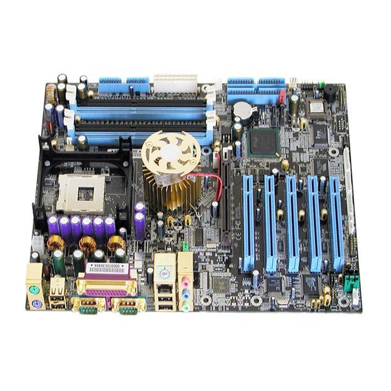
Page 12: 9Pjl Motherboard Layout
Chapter 1 1-5 9PJL Motherboard Layout... -
Page 13: Chapter 2 Hardware Setup
Chapter 2 Hardware Setup Chapter 2 If your motherboard has already been installed in your computer you may still need to refer to this chapter if you plan to upgrade your system's hardware. This motherboard is electrostatic sensitive. Do not touch without wearing proper safety gadget and make sure to disconnect the power cable from the power source before performing any work on your motherboard. -
Page 14: Setting Your Cpu's Parameters
Chapter 3 2-2 Setting your CPU’s Parameters Intel Hyper-Threading Technology Basic requirements for Intel’s Hyper-Threading Technology: CPU: An Intel® Pentium® 4 Processor with HT Technology; Chipset: An Intel® Chipset that supports HT Technology; BIOS: A BIOS that supports HT Technology and has it enabled; and OS: An operating system that supports HT Technology. - Page 15 Chapter 3 Boxed Processor FSB Chipset Support 800 MHz FSB processors require a new chipset Willamette (0.18) processors are not supported on 875/865 chipsets Processor Supporting Non-Supporting Chipsets Chipsets Intel Pentium 4 Processor 800 MHz 875P, 865G/PE 865P, 850E, 845(all) Intel Pentium 4 Processor 533 MHz 865G/PE/P, 850E, 845GL...
- Page 16 Chapter 3 How to Derive your CPU Core Speed? CPU Core Speed = CPU Clock * Core/Bus Ratio You do not need to change voltage settings because this board will automatically set your CPU voltage. Overclockability: This motherboard is designed to support overclocking ability. However, please make sure your peripherals are able to tolerate such abnormal settings while CPU clock speed is overclocked.
-
Page 17: Main Memory Configuration
Chapter 3 2-3 Main Memory Configuration This motherboard provides four 184pin Double Data Rate (DDR) Dual-In-line Memory Modules (DIMM) slots, which supports PC2100/2700/3200 DDR SDRAM modules up to 4GB. Install at least one DIMM module on the slots. Memory modules can be installed on the slots in any order. You can install either single- or double-sided modules to meet your own needs. - Page 18 Chapter 3 Memory Channel Modes Single Channel / Dual Channel Virtual Single Channel DIMM Population No restrictions Matching DIMM pairs Rank (Row) Size Size of one side of the 2x the size of one side of DIMM populated in the the DIMM populated in the channel channel (A or B)
- Page 19 Chapter 3 The following conditions must be met: –Matched DIMM configuration in each channel •Same Density (128MB, 256MB, 512MB, etc.) •Same DRAM technology (128Mb, 256Mb, or 512Mb) •Same DRAM bus width (x8 or x16) •Both either single-sided or dual-sided –Matched in both Channel A and Channel B memory channels •Populate symmetrical memory slots (Slot 0 or Slot 1) The following conditions do not need to be met: –Same brand...
- Page 20 Chapter 3 Maximizing Performance Optimal configurations for highest performance: –Matched, DDR400, Double-sided DIMMs –Dual Channel Mode (Symmetrical DIMM population) –Matched, DDR400, Dual Channel Mode When not using DDR400, highest performing configuration: –Symmetrical DIMM population with matched double-sided DIMMs –Lightly loaded memory population aids in higher performance –x8 Bus Width and lower DIMM cache latency also assists in higher performance Dual Channel memory configuration provides higher performance than Single Channel configurations...
-
Page 21: Connector And Jumper Reference Chart
Chapter 3 2-4 Connector and Jumper Reference Chart Jump Connector Function Page PW1 / 2 ATX Power Supply Connector CN1A Front Panel (Power / Rest / SPK…etc.) Connector Floppy Connector IDE1 / 2 IDE Hard-Disk Connector CMOS Clear Jumper Disable/Enable USB 0/1, 2/3 Device Power ON JP6 / 6A Jumper CPU / System / Case/ North Bridge Cooling Fan... -
Page 22: Connector And Jumper Settings
Before connecting the power supply, please make sure it is not connected to the power source. All cables that provided by CHAINTECH come with a security-proof. PW 1 / 2 (ATX Power Supply Connector): The power cord leading from the system's power supply to the external power source must be the very last part connected when assembling a system. - Page 23 Chapter 3 Blinking LED in Suspend Mode: While in Suspend mode, the LED light on the front panel of your computer will flash. Suspend mode is entered by pressing the Green Override Power Button on your ATX case, or by enabling the Power Management and Suspend Mode options in BIOS's Power Management menu.
- Page 24 Chapter 3 2. P-LED (Power LED Connector): The power indicator LED shows the system's power status. It is important to pay attention to the correct cable and pin orientation (i.e. Be careful not to reverse the order of these two connectors.) 3.
- Page 25 Chapter 3 IDE 1/2 (IDE Hard-Disk Connector) The motherboard has a 32-bit Enhanced PCI IDE and Ultra ATA66/100 controller that provides PIO mode 0~4, Bus Master, and Ultra ATA66/100 function. This connector is used for connecting 40 pins of ATAPI devices. IDE 1 only connects two IDE devices.
- Page 26 Chapter 3 3. Connect the system's power and then start the system. 4. Enter BIOS's CMOS Setup Utility and choose Load Setup Defaults. Type [Y] and then press [Enter] to continue. 5. Set the system configuration in the Standard CMOS Setup menu. JP6/JP6A (Enable/Disable USB 0/1, 2/3 Device Power ON Jumper) Definition Disable (default)
- Page 27 Chapter 3 The board's hardware management is able to detect the CPU and system fan speed in rpm (revolutions per minute). The wiring and plugging may vary depending on the manufacturer. On standard fans, the red is positive (+12V), the black is ground, and the yellow wire is the rotation signal.
- Page 28 Chapter 3 Enable the Wake Up On Modem selection in BIOS's Power Management Menu to activate this function. This header is used to connect an add-in modem card, which provides WOM function to the motherboard. CN17 (Blue LED Connector) This feature works exactly the same as the power indicator LED, of which both indicate the system’s power status.
- Page 29 (optional) cable ext. connector. Pins [5-6] and [9-10] are shorted (default) to enable the back-panel audio function. CN25 (CBOX™ 2 DigiDoc System Display Connector): CBOX™ 2 features CHAINTECH’s exclusive DigiDoc, the most advanced system diagnostic monitoring display. 80-PORT diagnostic display during POST at system boot up!
- Page 30 Chapter 3 IR 1 (IR Connector): Select the UART port used in UART Mode from BIOS's Integrated Peripherals menu to support IR function. (See section 3.4 Super I/O Device of Integrated Peripherals) CN26/26A/26B (IEEE1394 Connector) Attach the IEEE 1394 serial connector cable to 6GFKIT and CBOX™ 2 Front panel.
- Page 31 Chapter 3 JP3 / 3A (CPU Front Side Bus setting) EXT. Clock JP3A Default 100MHz 133MHz OPEN 166MHz OPEN OPEN 200MHz OPEN This function allows you to set the CPU’s FSB. The default setting is at pins [1-2], and your CPU’s FSB will be automatically detected. It is recommended that you leave the default settings to prevent any burnout on your CPU.
- Page 32 Chapter 3 JP23 (Green LED Mode Jumper) Definition 1-2 Normal (default) Reserve This is for setting up Green LED flash mode. (Optional) CN2/CN2A (CD-ROM Audio-in Connector) Use the audio cable enclosed with your CD-ROM disk drive to connect the CD-ROM to your motherboard. This will enable your CD-ROM's audio function.
- Page 33 Chapter 3 CN3 (Auxiliary Audio-in Connector) (Optional) This connector is for Auxiliary Audio-in Device. CN4B (AC3 Center / Surround + Bass Connector) This connector must be connected to 6GFKIT.
- Page 34 Chapter 3 CN9A (Chassis Open Alarm Connector) This connector provides a buzzer sound when an attempt to open the chassis occurs. Note: Only certain chassis provides this function. CN27 Game Port Connector This connector must be connected to 6GFKIT.
-
Page 35: Serial Ata And Parallel Ata
Chapter 3 2-6 Serial ATA and Parallel ATA SATA & PATA configurations 1. Compatible mode - Older OSs don’t support switch to native mode (DOS, Win2K, Win98/ME…) should set SATA and PATA to Compatible Mode. Maximum 4 ATA devices Combine mode and Non-Combine mode 2. - Page 36 Chapter 3 Option 3 – Combined Mode S-ATA devices P-ATA devices Maximum of 2 Each (3a) (3b) (3c) (3d) Enhanced Mode Enable S-ATA & P-ATA Max 6 ATA (4 P-ATA + 2 S-ATA)
-
Page 37: Cbox™ 2 And 6Gfkit Setup
CN27 CN27 Remove CN24 Jumper Caps on motherboard 5-6, 9-10 before installation. USB Cable (10 pin) Front Audio Cable (10 pin) IEEE-1394 Cable (8 pin) 80 Port Display (10 pin) All cables that provided by CHAINTECH come with a security-proof. -
Page 38: Chapter 3 Bios Setup Program
Chapter 3 BIOS Setup Program Chapter 3 Phoenix-Award BIOS ROM has a built-in setup program that allows users to modify the basic system configuration. This information is stored in CMOS RAM so that it can retain the setup information even when the power is turned off. To enter the Phoenix-Award BIOS setup program: 1. -
Page 39: Standard Cmos Setup
Chapter 3 3-1 Standard CMOS Setup The Standard CMOS Setup allows users to configure system components such as hard-disk drive, floppy-disk drive and video display as well as date, time and boot up error signaling. This configuration menu should be changed when installing a motherboard for the first time, or changing hardware such as HDD, FDD, and video display in your system, or when the CMOS data was lost or corrupted. -
Page 40: Advanced Bios Features
Chapter 3 POST (Power On Self Test). This function stops the computer if BIOS detects a hardware error. You can tell BIOS to halt on all errors, no errors, or not to halt on specific errors. 3-2 Advanced BIOS Features By choosing the Advanced BIOS Features option from the CMOS Setup Utility menu (Figure 3-1), the screen that lists the manufacturer's default values for the motherboard is displayed below. -
Page 41: Keyboard Interface
Chapter 3 performance of your computer. Hyper-Threading Technology Available options are [Enabled] and [Disabled]. Select [Enable] to support Hyper-Threading Technology and vice versa. Quick Power On Self Test: Enable this function to reduce the amount of time required to run the POST (Power On Self Test). - Page 42 Chapter 3 take advantage of this function. See Section 3.11 for password setting information. When the Security Option is set to System, a password must be entered to boot up the system or enter the BIOS setup program. When the Security Option is set to Setup, a password is required to enter the BIOS setup program.
-
Page 43: Advanced Chipset Features
Chapter 3 3-3 Advanced Chipset Features By choosing the [Advanced Chipset Features] option from the CMOS Setup Utility menu (Figure 3-1), the screen that lists the manufacturer's default values for the motherboard is displayed below. Figure 3-4 Advanced Chipset Features All of the above settings have been determined by the motherboard manufacturer and should not be changed unless you are absolutely sure of what you are doing. - Page 44 Chapter 3 DRAM RAS# Precharge This item controls the idle clocks after issuing Precharge command to the DRAM. Memory Frequency For Please leave the default system setting as [Auto] for a stable system operation. WARNING Overclockability: This motherboard is designed to support overclocking ability. However, please make sure your peripherals are able to tolerate such abnormal setting, while CPU clock speed is overclocked.
-
Page 45: Integrated Peripherals
Chapter 3 allocation in that the AGP card will only use the amount of memory that it needs. The remaining unused memory is also available for system usage. For example, if 16MB is allocated to the AGP card and the card only needs 8MB, the remaining 8MB will be available for system usage. - Page 46 Chapter 3 support. 2. On-Chip Primary/Secondary PCI IDE You can set this to disable the On Chip IDE controller if you are going to add a higher performance IDE board. 3. IDE Primary/Secondary Master/Slave PIO: The four IDE PIO (programmed Input/Output) fields let you set a PIO mode (0-4) for each IDE device that the internal PCI IDE interface supports.
- Page 47 Chapter 3 2. USB 2.0 controller This entry is for disable/enable EHCI controller only. This BIOS itself may/may not have high speed USB support. If the BIOS has high speed USB support built in, the support will automatically be turned on when high speed device were attached. 3.
- Page 48 Chapter 3 4. UR2 Duplex Mode: Available options: [Half] and [Full]. 5. Onboard Parallel Port: Select a logical LPT port address and the corresponding interrupt for the physical parallel port. 6. Parallel Port Mode: Select an operating mode for the onboard parallel (printer) port. Select SPP unless you are certain that your hardware and software support one of the other available modes.
-
Page 49: Power Management Setup
Chapter 3 3-5 Power Management Setup This section provides information on the Green PC power management functions. By choosing the Power Management Setup option from the CMOS Setup Utility menu (Figure 3-1), the screen that lists the manufacturer's default values for the motherboard is displayed below. - Page 50 Chapter 3 synchronization ports, writes blanks to the VGA buffer and the monitor's electron gun turns off. This function requires monitors with Green features in order to take advantage of the power-saving function. If you enable this function and do not have a Green monitor, the result will be the same as if you had selected Blank.
- Page 51 Chapter 3 2. Power On by Ring: When enabled, a Modem will be able to receive a signal and activate the system from soft off and green mode. You should connect the modem to the COM port and signal your PC to power on. 3.
-
Page 52: Pnp/Pci Configurations
Chapter 3 3-6 PNP/PCI Configurations This section provides IRQ and DMA setting information. By choosing the PNP/PCI Configuration option from the CMOS Setup Utility menu (Figure 3-1), the screen that lists the manufacturer's default values for the motherboard is displayed below. Figure 3-7 PNP/PCI Configurations Reset Configuration Data: Default is [Disabled]. -
Page 53: Pc Health Status
Chapter 3 FDD IRQ Can Be Free: This function allows users to choose if the FDD IRQ can be freed up. The default setting is [Yes]. 3-7 PC Health Status By choosing the PC Health Status option from the CMOS Setup Utility menu (Figure 3-1), the screen below is displayed. -
Page 54: Frequency/Voltage Control
Chapter 3 3-8 Frequency/Voltage Control By choosing the Frequency/Voltage Control option from the CMOS Setup Utility menu (Figure 3-1), the screen that lists the manufacturer's default values for the motherboard is displayed below. Figure 3-9 Frequency/Voltage Control Auto Detect PCI Clk Available options are [Enabled] and [Disabled]. -
Page 55: Load Fail-Safe Defaults
Chapter 3 Voltage Fine Tune Please leave the default setting as [Disable] for a stable system operation. Available options are [Enabled] and [Disabled]. 3-9 Load Fail-Safe Defaults Load Fail-Safe Defaults loads the default BIOS values directly from the CMOS Setup Utility menu (Figure3-1). If user-defined BIOS settings are corrupted and therefore unusable, these defaults will be loaded automatically when you turn on the computer. -
Page 56: Exit Without Saving
Chapter 3 utilities will be recorded in the CMOS memory of the BIOS chip. 3-13 Exit Without Saving Selecting this option and pressing [Y] followed by [Enter] lets you exit the Setup program without recording any new values or changing old ones. -
Page 57: Chapter 4 Driver Setup
Chapter 4 DRIVER Setup Chapter 4 Insert the support CD that come with your motherboard into your CD-ROM driver or double-click the CD drive icon in [My computer] to enter the setup screen. 4-1 Intel® IDE Bus Mastering Drivers Setup 1. - Page 58 Chapter 4 3. Click [Yes] to accept the license agreement 4. Select [Next] to continue.
-
Page 59: C-Media Sound Driver Setup
Chapter 4 5. Please select [Yes] to restart computer now or [No] to restart later, and then click on [Finish] to complete the installation. 4-2 C-Media Sound Driver Setup This section provides information on installing audio devices by choosing [Audio Driver] from the Setup Driver menu. 1. - Page 60 Chapter 4 2. Select [Audio Drivers] to begin the software installation 3. Select [Install Device Driver and Applications].
- Page 61 Chapter 4 4. Select the setup language and click [OK] to continue. 5. Click [Next] to proceed. 6. Please select a folder where the program will be installed and click on [Next >] to proceed.
- Page 62 Chapter 4 7. Please select one folder from existing list of folders and click on [Next >] to proceed. 8. Please select [Yes] to restart computer now or [No] to restart later, and then click [OK] to complete the installation.
-
Page 63: Intel® Lan Driver Setup
Chapter 4 4-3 Intel® LAN Driver Setup 1. Click [LAN Driver] 2. Click [Next >] to continue. -
Page 64: Usb 2.0 Driver
Chapter 4 3. Click [Finish] to complete setup 4-4 USB 2.0 Driver Open Device Manager and open the properties for the USB 2.0 host controller. Select 'Update Driver'. Point the installer to the folder with the USB 2.0 drivers. It should select the CD-ROM:\intel\usb2\win2k_XP\ich5usb2_win2k (for Win 2000 /XP or CD-ROM:\intel\usb2\win98&me (for 98se / ME) and then install the system files. -
Page 65: Chapter 5 Audio Device Application
Chapter 4 Chapter 5 Audio Device Application This sound card supports Windows 95/98/ME/NT4.0/2000 operating systems. To start the Audio Application Program simply select from menu [Start]→[Program Files]→[PCI Audio Applications]→[Audio Rack]. It includes the following options: a) Audio Rack: Which includes Audio Rack, CD Player, MIDI Player, Mixer and MP3 Player. b) Multi-Channel Audio Demo: (Windows NT4.0 is not supported) Demonstrations of Multi-Channel Audio. - Page 66 Appendix 1. C-Media Mixer Volume a) Volume Control You can simply double-click the icon located at button right corner of Windows to open the C-Media Mixer volume control. This control panel includes Master Volume, CD Audio, Microphone, WAVE, SW Synth, A/V (AUX) In, MONO IN, and LINE IN. b) Mixer Recording Control This control panel includes CD Audio, Microphone, WAVE, Stereo Mix, A/V (AUX IN), and LINE IN.
- Page 67 Appendix Mixer Advance Setting: 1) SPDIF: a) Output: S/PDIF Playback: It activates SPDIF OUT. (SPDIF Out only applies to earphone and 2 speakers.) Sampling Rate: Transfer the Wave file from computer to any digital media devices through optical fiber, e.g. MD or DAT Advanced media devices.
- Page 68 Appendix Format: Select between Normal and Reverse. Device: For device features select from S/PDIF #1 and S/PDIF Copyright Protection: Audio files have copyrights. Please select this option to prevent pirate copies. 2) Speakers: Headset & 2 channel speaker setup 4 channel speaker setup...
- Page 69 Appendix 6 channel speaker setup User 4ch XeaR mode setup User 6ch XeaR mode setup...
- Page 70 Appendix 3) Volume: 4) Sound Effect: 5) Option: 【Enable Hot-Key Setting】 This provides Hot-Keys settings of Volume control, Mute, and Display. 【Enable Microphone Booster】 Enable the microphone’s electrical circuit to increases the sensitivity of the microphone. When designing the audio chip, it limits the type of microphones that are available.
- Page 71 Appendix microphone. The one that Karaoke uses does not work on this chip. 【Load Mixer Defaults】 This loads the original default setting of Sound Effects. (It restores Volume, Wave, and MIDI.) 2. CD Player Output Configuration: Setup: Enabled to choose the Audio CD drive of your system. •...
- Page 72 Appendix Setup: a) Under Win 95 / 98 3 options are available for the Output device: [Default MidiOut Device], [Roland MPU-401], [Microsoft GS Wavetable SW Synth]. b) Under Windows NT4.0 Only CMPCI MIDI device is available. c) Under Windows 2000 / ME / XP 3 options are available for Output device: [Default MidiOut Device], [Microsoft GS Wavetable SW Synth], [Roland MPU-401].
- Page 73 Appendix c) Surround: This is for setting up the speaker output mode. d) Playback Mode: This is for selecting the music playback mode. Configuration: Playback: Plays back delay time for mini- disk recordings. Please use the default setting. Recording Configuration: Recording Format: Quality: a) Name:...
-
Page 74: Multi-Channel Demo
Appendix 5-2 Multi-Channel Demo Select from menu [ Start ] → [ Program ] → [ PCI Audio Applications ] → [ Multi-Channel Demo ] Click on the TV screen at the center to enter the [Advanced] screen. Set speaker function for demo mode: Set EAX function for demo mode: In Advance mode, here you can configure according to your system hardware or personal preferences. -
Page 75: Appendix
Appendix Appendix Digidoc 80-Port POST Error Code List POST (hex) Description Test CMOS R/W functionality. Early chipset initialization: -Disable shadow RAM -Disable L2 cache (socket 7 or below) -Program basic chipset registers. Detect memory: -Auto-detection of DRAM size, type and ECC. -Auto-detection of L2 cache (socket 7 or below) Expand compressed BIOS code to DRAM. - Page 76 Appendix Initial Early_Init_Onboard_Generator switch. Detect CPU information including brand, SMI type (Cyrix or Intel®) and CPU level (586 or 686). Initial interrupts vector table. If no special specified, all H/W interrupts are directed to SPURIOUS_INT_HDLR & S/W interrupts to SPURIOUS_soft_HDLR. Initial EARLY_PM_INIT switch.
- Page 77 Appendix Test 8259 interrupt mask bits for channel 2. Test 8259 functionality. Initialize EISA slot 1. Calculate total memory by testing the last double word of each 64K page. 2. Program writes allocation for AMD K5 CPU. 1. Program MTRR of M1 CPU 2.
- Page 78 Appendix 2. Set up floppy related fields in 40:hardware. (Optional Feature) Enter AWDFLASH.EXE if: - AwdFlash is found in floppy drive. - ALT+F2 is pressed. Detect & install all IDE devices: HDD, LS120, ZIP, CDROM Detect serial ports & parallel ports. Detect &...
- Page 79 Appendix 1. Build MP table 2. Build & update ESCD. 3. Set CMOS century to 20h or 19h 4. Load CMOS time into DOS timer tick. 5. Build MSIRQ routing table. Boot attempt (INT 19h)
-
Page 80: How To Contact Chaintech
How to contact CHAINTECH How To Contact CHAINTECH Please do not hesitate to contact us if you have any problem about our products. Any opinion will be appreciated. For Asia, Africa, Australia and Pacific Island: For UK: CHAINTECH COMPUTER CO., LTD CHAINTECH UK., LTD. - Page 81 NOTE NOTE All rights are reserved for the products and corporate names/logos that appear in this manual to their original owners. CHAINTECH reserves all the rights to change this manual .All information is subject to change without notice.
Need help?
Do you have a question about the CT-9PJL and is the answer not in the manual?
Questions and answers