Table of Contents
Advertisement
Quick Links
Federal Communications Commission Statement
This device complies with FCC Rules Part 155. Operation is subject to the following two
conditions:
w
This device may not cause harmful interference
w
This device must accept any interference received, including interference that may
cause undesired operation.
This equipment has been tested and found to comply with the limits for a Class B digital
device, pursuant to Part 15 of the FCC Rules. These limits are designed to provide
reasonable protection against harmful interference in a residential installation. This equipment
generates, uses and can radiate radio frequency energy. If this equipment is not installed
and used in accordance with the manufacturer's instructions, it may cause harmful
interference to radio communications. However, there is no guarantee that interference will
not occur in a particular installation. If this equipment does cause harmful interference to
radio or television reception, which can be determined by turning the equipment off and
on, the user is encouraged to try to correct the interference by one or more of the
following measures:
w
Reorient or relocate the receiving antenna.
w
Increase the separation between the equipment and receiver.
w
Connect the equipment to an outlet on a circuit different from that to which the
receiver is connected.
w
Consult the dealer or an experienced radio/TV technician for help.
The use of shielded cables for connection of the monitor to the graphics card is required
to assure compliance with FCC regulations. Changes or modifications to this unit not
expressly approved by the party responsible for compliance could void the user's authority
to operate this equipment.
Canadian Department of Communications Statement
This digital apparatus does not exceed the Class B limits for audio noise emissions from
digital apparatusses set out in the Radio Interference Regulations of the Canadian
Department of Communications.
Manufacturer's Disclaimer Statement
The information in this document is subject to change without notice and does not represent a
commitment on the part of the vendor. No warranty or representation, either expressed or implied,
is made with respect to the quality, accuracy or fitness for any particular purpose of this document.
The manufacturer reserves the right to make changes to the content of this document and/or the
products associated with it at any time without obligation to notify any person or organization of
such changes. In no event will the manufacturer be liable for direct, indirect, special, incidental
or consequential damages arising out of the use or inability to use this product or documentation,
even if advised of the possibility of such damages. This document contains materials protected
by copyright. All rights are reserved. No part of this manual may be reproduced or transmitted
in any form, by any means or for any purpose without expressed written consent of it's authors.
Product names appearing in this document are mentioned for identification purposes only. All
trademarks, product names or brand names appearing in this document are registered property
of their respective owners.
Printed in Taiwan
April 1998
April 1998
April 1998
April 1998
April 1998
POST-CONSUMER
RECYCLED PAPER
i
Advertisement
Table of Contents

Related Manuals for CHAINTECH CT-6BTM


Summary of Contents for CHAINTECH CT-6BTM
- Page 1 Federal Communications Commission Statement This device complies with FCC Rules Part 155. Operation is subject to the following two conditions: This device may not cause harmful interference This device must accept any interference received, including interference that may cause undesired operation. This equipment has been tested and found to comply with the limits for a Class B digital device, pursuant to Part 15 of the FCC Rules.
-
Page 2: Table Of Contents
Table of Contents Chapter 1 Introduction ................. 1 Product Specifications ............1 Package Contents ..............4 Mainboard Layout ..............5 Connector and Jumper Reference Chart ....... 5 Chapter 2 Hardware Setup ..............7 Introduction to Jumpers ............7 Installing an S.E.C. Processor in Slot 1 ....... 8 Setting Your CPU's Parameters( SeePU Technology) .... - Page 3 Over-ride Power Button ................. 12 Blinking LED in Suspend Mode ............12 Wake Up On LAN ................14/34 Creative's SB-LINK Sound ..............15 Power-On by Keyboard ..............15/40 Poly-fuse Over Current Protection ............16 Chassis Intrusion Monitoring ..............16 Power Failure Recovery ..............16/29 ECC DRAM Capability .................
- Page 4 - Memo...
-
Page 5: Chapter 1 Introduction
Introduction Chapter 1 Introduction 1-1 Product Specifications r r r r r Processor ® - Supports up to 450 MHz Intel Pentium II processors - Slot 1 CPU socket with retention mechanism - High efficiency Switching Power Module (1.8v ~ 3.5v, 0.1v increments) - Supports 66/100 MHz system clock speeds - Innovative SeePU technology (software CPU installation with no jumper settings) - Page 6 Chapter 1 The Trend ChipAway Virus is a rule-based anti-virus technology and does not require periodical updates of virus code r r r r r Two Ultra DMA-33 PCI IDE Ports - Supports up to PIO Mode 4, Multi-word Mode 2 and Ultra DMA-33 timings - Bus Mastering software drivers for all well known multi-task operating systems r r r r r On-board Ultra I/O...
- Page 7 Introduction r r r r r Switching Power Supply Requirement (at least 200 Watts) Max. Regulation Min. Current Output Voltage Requirement Requirement (Amps) +12V +/- 5% +/- 5% +3.3V +/- 5% +/- 10% -12V +/- 10% +5VSB +/- 5% 0.05 Table 1-1 * 3.3V at 10Amps is necessary too guarantee full loading operation because some AGP cards and memory modules have high current...
-
Page 8: Package Contents
Chapter 1 1-2 Package Contents This product comes with the following components: r One mainboard r On-board Slot 1 foldable retention mechanism and four screws r One 40-pin IDE connector ribbon cable (Figure 1-1) r One 34-pin floppy disk drive ribbon cable (Figure 1-2a) or (Figure 1-2b) r One User's Manual r One CD-ROM that includes - Award Flash EPROM Utility, Award DMI Utility... -
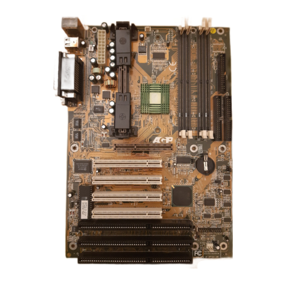
Page 9: Mainboard Layout
Introduction 1-3 Mainboard Layout 1-4 Connector and Jumper Reference Chart Jumper & Ref. Function Connector No. page Chassis intrusion monitoring connector WOL (Wake-on-LAN) Connector Infrared connector ATX power supply connector Creative's SB-LINK connector Green switch connector Green LED connector System reset switch connector Turbo LED connector CN10 Keyboard lock &... - Page 10 Chapter 1 - Memo...
-
Page 11: Chapter 2 Hardware Setup
Hardware Setup Chapter 2 Hardware Setup If your mainboard has already been installed in your computer you may still need to refer to this chapter if you plan to upgrade your system's hardware. Be sure to disconnect the power cable from the power source before performing any work on your mainboard, i. -
Page 12: Installing An S.e.c. Processor In Slot 1
Chapter 2 2-2 Installing an S.E.C. Processor in Slot 1 1. Insert the Pentium II processor into the retention mechanism. Press evenly and gently until the snaps on the upper side of the processor have been inserted into the holes at the top of the retention mechanism. 2. -
Page 13: Setting Your Cpu's Parameters( Seepu Technology)
Hardware Setup 2-3 Setting Your CPU's Parameters( SeePU Technology) SeePU is a new user friendly technology that enables the user to setup a mainboard's CPU parameters through an easy to use BIOS setup procedure. It is no longer necessary to make many jumper settings as on conventional mainboards. 1. - Page 14 Chapter 2 You do not need to make voltage settings because SeePU automatically sets your CPU voltage. ROM PCI / ISA BIOS (2A69KC39) SeePU & CHIPSET SETUP AWARD SOFTWARE, INC. Power Failure Recovery : Disabled SDRAM CAS latency Time Spectrum Spread : Disabled DRAM Data Integrity Mode : Non-ECC...
-
Page 15: Connector And Jumper Settings
Hardware Setup 2-4 Connector and Jumper Settings Connectors are used to link the system board with other parts of the system, including the power supply, the keyboard, and the various controllers on the front panel of the system case. The power supply connector is the last connection to be made while installing a mainboard. -
Page 16: Over-Ride Power Button
Chapter 2 Front Panel Connector Set (CN10) A through G A. Over-ride Power Button Connector The power button on the ATX chassis can be used as a normal power switch as well as a button to activate Advanced Power Management Suspend mode. This mode is used for saving electricity when the computer is not in use for long periods of time. - Page 17 Hardware Setup C. Green Switch/Green LED Connector Some ATX cases provide a Green switch which is used to put the system in Suspend mode. In Suspend mode, the power supply to the system is reduced to a trickle, the CPU clock is stopped, and the CPU core is in it's minimum power state.
-
Page 18: Wake Up On Lan
Chapter 2 Infrared Connector (CN3) If you enable the COM2 Mode in BIOS's Integrated Peripherals menu the COM2 port will support IR functions. (See section 3-7) CPU/System Cooling Fan Connectors (CPUFAN/SYSFAN) These added connectors allow the fan to draw their power from the mainboard instead of the disk drive connector. -
Page 19: Creative's Sb-Link Sound
Hardware Setup Creative's SB-LINK Sound Connector (CN8) The SB-LINK serves as a bridge between the mainboard and Creative's PCI sound card. This connector delivers Sound Blaster 16 compatility for real-mode DOS games. Clear CMOS Data Jumper (JP6) Normal (default) Clear CMOS data To clear the contents of the CMOS, please follow the steps below. -
Page 20: Poly-Fuse Over Current Protection
Chapter 2 PS/2 Mouse and Keyboard Ports If a PS/2 mouse is used, BIOS will automatically detect and assign IRQ12 to the PS/2 mouse. Definition Data No Connect Ground +5V (fused) Clock No Connect Poly-fuse Over Current Protection The poly-fuse protects the system from dangerous voltages the system might be exposed to via the keyboard or USB connectors. - Page 21 Hardware Setup USB(Universal Serial Bus) Ports If you want to use a USB keyboard, you must enable the USB keyboard support function in BIOS's Integrated Peripherals menu (See Section 3-7). USB is an open industry standard, providing a simple and inexpensive way to connect up to 125 devices to a single computer port.
-
Page 22: Main Memory Configuration
Chapter 2 2-5 Main Memory Configuration The DRAM memory system consists four banks and the memory size ranges from 16~512 MBytes. If you only use one bank it does not matter which one you use and if you use two or more banks, it does not matter which bank you install first. DRAM Specifications System Frequency SDRAM Type Max Memory... -
Page 23: Ecc Dram Capability
Hardware Setup SPD (Serial Presence Detect) This is an EPROM that contains speed and design information about the memory module. The mainboard queries the module and makes adjustments to system operation based on what it finds. ECC DRAM Capability This mainboard can be configured to support ECC (Error Check and Correct) function when utilizing parity DIMM modules. - Page 24 Chapter 2 - Memo...
-
Page 25: Chapter 3 Award Bios Setup Program
Award BIOS Setup Program Chapter 3 Award BIOS Setup Program Award's BIOS ROM has a built-in setup program that allows users to modify the basic system configuration. This information is stored in CMOS RAM so that it can retain the setup information, even when the power is turned off. When you turn on or reboot the system, press the Delete key to enter the Award BIOS setup program. -
Page 26: Standard Cmos Setup
User's Manual 3-1 Standard CMOS Setup The Standard CMOS Setup allows users to configure system components such as hard disk drive, floppy disk drive and video display as well as date, time and boot- up error signaling. This configuration menu should be changed when installing a mainboard for the first time, changing hardware in your system such as the HDD, FDD, video display, or when the CMOS data has been lost or contaminated. - Page 27 Award BIOS Setup Program Type (Auto/User/None): Use the fields under the Type column to determine the method you will use to configure the IDE devices. If you choose Auto, BIOS will automatically detect and make optimal settings for most IDE hard drives. The mainboard manufacturer recommends that you choose Auto for all drives.
- Page 28 User's Manual Large - for IDE drives that do not support LBA and have more than 1024 cylinders. Try this setting if your hard disk does not operate properly with the LBA setting. Large mode is not supported by all operating systems, i.e., only certain versions of DOS support large mode.
-
Page 29: Bios Features Setup
Award BIOS Setup Program 3-2 BIOS Features Setup By choosing the BIOS Features Setup option from the CMOS Setup Utility menu (Figure 3-1), the screen below is displayed. This sample screen contains the manufacturer's default values for the mainboard. ROM PCI / ISA BIOS (2A69KC39) BIOS FEATURES SETUP AWARD SOFTWARE, INC. - Page 30 User's Manual 2 external cache. Both settings are left enabled to significantly increase the performance of your computer. CPU L2 Cache ECC Checking Enable this function to perform ECC (Error Check and Correct) on the CPU's L2 SRAM. ECC detects and corrects single-bit errors while it only detects double bit errors.
- Page 31 Award BIOS Setup Program Typematic Rate (Chars/Sec) The typematic rate sets the rate at which characters on the screen repeat when a key is pressed and held down. Typematic Delay (Msec) The typematic delay sets how long after you press a key that a character begins repeating.
-
Page 32: Seepu & Chipset Setup
User's Manual 3-3 SeePU & Chipset Setup By choosing the SeePU & Chipset Setup option from the CMOS SETUP UTILITY menu(Figure 3-1), the screen below is displayed. This sample screen contains the manufacturer's default values for the mainboard. ROM PCI / ISA BIOS (2A69KC39) SeePU &... -
Page 33: Power Failure Recovery
Award BIOS Setup Program B. System BIOS Cacheable Enabling this function allows caching of the system BIOS ROM at F0000h- FFFFFh, resulting in better system performance. However, if any program writes to this memory area, a system error may result. Caching the system BIOS results in better performance than shadowing the system BIOS as discussed in Section 3-2. -
Page 34: Flash Bios Protection
User's Manual H. Spectrum Spread When Enabled this function will cause lower EMI by spreading the system frequency spectrum. While this function decreases EMI, system stability may be slightly compromised. Choosing Smart Clock will turn off the AGP, PCI, and SDRAM clocks when not in use. Smart Clock does not perform a spectum spreading function. -
Page 35: Power Management Setup
Award BIOS Setup Program 3-4 Power Management Setup This section provides information on the Green PC power management funtcions. By choosing the Power Management Setup option from the CMOS Setup Utility menu (Figure 3-1), the screen below is displayed. This sample screen contains the manufacturer's default values for the mainboard. - Page 36 User's Manual Maximum Saving, User Define, or Minimum Saving described below. For a description of the power saving modes (Doze, Standby, and Suspend) see their descriptions below. Disabled - Turns off the Power Management functions. Max. Saving - All timers are set at the minimum value of one minute to maximize power saving.
- Page 37 Award BIOS Setup Program DPMS Supported - Select this option if your video card supports the Display Power Management Signaling (DPMS) standard (i.e., you have a monitor that supports Green features). Use software supplied by your your video subsystem to set video power management options. D.
-
Page 38: Power-On By Alarm
User's Manual H. Suspend Mode The Power Management function must not be set to disabled to enable this function. If the system runs in Standby mode and the Suspend timer expires, all devices regulated by power management will shut off and the CPU speed will be 0 MHz. - Page 39 Award BIOS Setup Program function is only available when using an ATX power supply and the Software Power- Off function to turn off the computer. See the Software Power-Off feature in Section 2-4 of this manual for instructions. P. IRQ8 Break Suspend Enabling this setting turns the monitoring of IRQ8 (the Real Time Clock) On so it does not awaken the system from Suspend mode.
-
Page 40: Pnp/Pci Configuration
User's Manual 3-5 PNP/PCI Configuration This section provides IRQ and DMA setting information. By choosing the PNP/ PCI Configuration option from the CMOS Setup Utility menu (Figure 3-1), the screen below is displayed. This sample screen contains the manufacturer's default values for the mainboard. - Page 41 Award BIOS Setup Program C. Reset Configuration Data When enabled the system BIOS will clear/reset the ESCD during POST. After clearing the ESCD, the BIOS will then change this item's value to Disabled. Otherwise, the ESCD data will become useless. D.
-
Page 42: Load Setup Defaults
User's Manual 3-6 Load Setup Defaults Load Setup Defaults loads the default system values directly from the CMOS Setup Utility menu (Figure3-1). If the stored record created by the setup program becomes corrupted and therefore unusable, these defaults will be loaded automatically when you turn on the computer. -
Page 43: Integrated Peripherals
Award BIOS Setup Program 3-7 Integrated Peripherals This section provides information on setting peripheral devices. By choosing the Integrated Peripherals option from the CMOS Setup Utility menu (Figure 3-1), the screen below is displayed. This sample screen contains the manufacturer's default values for the mainboard. - Page 44 User's Manual B. Power On By Keyboard Set to Disabled to control your computer's power by the button on your system case. Set this function to Any Key to turn on the computer by touching any key on the keyboard. If you set this function to Hot Key or Password you must designate the keystrokes that will turn on the computer.
-
Page 45: Supervisor Password & User Password Setting
Award BIOS Setup Program 3-8 Supervisor Password & User Password Setting There are four different variables that control password settings. The first two are located under the Security Option function in BIOS Features Setup Menu (Figure 3-3). When the Security Option function is set to Setup, a password is required to enter BIOS and change BIOS settings. - Page 46 User's Manual B. Set Both Supervisor Password and User Password Figure 3-11 Set Both Supervisor and User Password...
-
Page 47: Ide Hdd Auto Detection
Award BIOS Setup Program 3-9 IDE HDD Auto Detection This utility can automatically detect IDE hard disk type and parameters. The detection process take about 5 seconds for each physical drive. After the utility detects the disk drive, type Y and press [Enter] to automatically load the parameters in the Hard Disk section of the Standard CMOS Setup menu. - Page 48 User's Manual - Memo...
-
Page 49: Chapter 4 Brief Software Driver Guide
Brief Software Driver Guide Chapter 4 Brief Software Driver Guide The Mainboard Software Guide is found on the CD-ROM that is enclosed with your mainboard and is a PDF file which must be viewed with Adobe's freeware called ® Acrobat Reader. - Page 50 Chapter 4 - Memo...
-
Page 51: Appendix I On Board I/O Addresses & Irq Maps
Introduction Appendix I On Board I/O Addresses & IRQ Maps System Resource I/O Address 1. Timer IRQ0 040, 043 2. Keyboard IRQ1 060, 064 3. Programmable INT IRQ2 0020, 0021, 00A0, 00A1 4. COM2(B) IRQ3 2F8, 2FF 5. COM1(A) IRQ4 3F8, 3FF 6. - Page 52 User's Manual - Memo...
-
Page 53: Appendix Ii Quick Connector And Jumper Reference
Appendix II Quick Connector and Jumper Reference Quick Connector and Jumper Reference Quick Connector and Jumper Reference Quick Connector and Jumper Reference Quick Connector and Jumper Reference CPUFAN/SYSFAN: CPU/System cooling fan connector CN1: Chassis intrusion monitoring connector CN2: WOL (Wake-on-LAN) Conn. SeePU (Jumper free CPU installation) setting table CN3: Infrared connector CPU Speed... - Page 54 - Memo...
-
Page 55: Appendix Iii Fan-Ii Smart Technology Upgrade Kit
Appendix III FAN-II: SMART Technology Upgrade Kit FAN-II System Monitor Software for Win95 The FAN-II upgrade kit provides a PC self-dialogistic capability called the SMART (System Monitoring and Alerting) technology. Features - Detects four on-board voltages (CPU Core Voltage, 3.3V, 5V, 12V) - Two fan speed sensing - One precise CPU temperature sensor and one chassis temperature sensor - Four types of speaker-driver signal output... - Page 56 - Memo...
Need help?
Do you have a question about the CT-6BTM and is the answer not in the manual?
Questions and answers