Advertisement
Quick Links
Declaration of Conformity
9VIL3
According to 47 CFR, Parts 2 and 15 of the FCC Rules
The following designated product:
Intel Socket 478
VIA P4X400 + VT8235
EQUIPMENT: MAINBOARD
MODEL NO.: CT-9VIL3
u-ATX Motherboard
is a Class B digital device that complies with 47 CFR Parts 2 and 15 of the FCC
Rules. Operation is subject to the following two conditions:
User's Guide
1. This device may not cause harmful interference.
2. This device must accept any interference received, including interference that
may cause undesired operation.
This declaration is given to the manufacturer:
CHAINTECH-EXCEL COMPUTER INC.
Version 1.0
4427 Enterprise St. Fremont, CA 94538, U.S.A.
http://www.chaintechusa.com
Chaintech President: Simon Ho
Signature:
Advertisement

Subscribe to Our Youtube Channel
Related Manuals for CHAINTECH 9VIL3


Summary of Contents for CHAINTECH 9VIL3
- Page 1 Intel Socket 478 VIA P4X400 + VT8235 EQUIPMENT: MAINBOARD MODEL NO.: CT-9VIL3 u-ATX Motherboard is a Class B digital device that complies with 47 CFR Parts 2 and 15 of the FCC Rules. Operation is subject to the following two conditions: User’s Guide...
- Page 2 1-2 Package Contents .................... 2 Part 15 of the FCC Rules. These limits are designed to provide reasonable protection against harmful interference 1-3 9VIL3 Motherboard Layout ................3 in a residential installation. This equipment generates, uses, and can radiate radio frequency energy. If this equipment is not installed and used in accordance with the manufacturer's instructions, it may cause harmful Hardware Setup............4...
- Page 3 Chapter 1 Chapter 1 Boot-Block Flash ROM Introduction Chapter 1 Award system BIOS supports PnP, APM, DMI, ACPI, & Multi-device booting 1-1 Product Specifications features. Processor Supports Intel Celeron/Pentium 4 Socket 478 CPU Supports Intel Celeron/Pentium 4 system bus at 400/533MHz 1-2 Package Contents Chipset This product comes with the following components:...
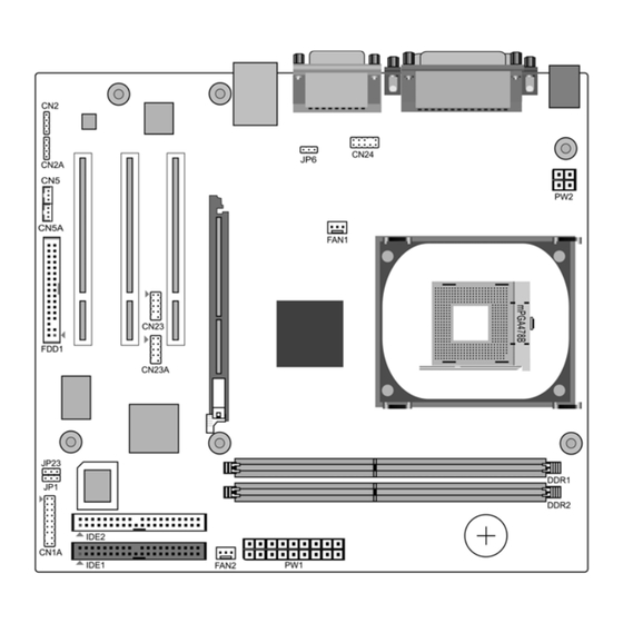
- Page 4 Chapter 1 Chapter 2 1-3 9VIL3 Motherboard Layout Hardware Setup Chapter 2 If your motherboard has already been installed in your computer you may still need to refer to this chapter if you plan to upgrade your system's hardware. This motherboard is electrostatic sensitive. Do not touch without...
- Page 5 2-3 Main Memory Configuration All cables that provided by CHAINTECH come with a security-proof. The DDR SDRAM memory system consists of two banks and can support memory size up to 1 GB per DIMM. If you only use one bank it does not matter which one...
- Page 6 Chapter 2 Chapter 2 Blinking LED in Suspend Mode 2. P-LED (Power LED Connector) While in Suspend mode, the LED light on the front panel of your computer will The power indicator LED shows the system's power status. It is important to pay flash.
- Page 7 Chapter 2 Chapter 2 IDE 1/2 (IDE Hard-Disk Connector) 5. Set the system configuration in the Standard CMOS Setup menu. JP6 (Enable/Disable USB 0/1 Device Wake-Up Jumper) Definition Disable (default) Enable The motherboard has a 32-bit Enhanced PCI IDE and Ultra ATA66/100 controller that provides PIO mode 0~4, Bus Master, and Ultra ATA66/100 function.
- Page 8 Chapter 2 Chapter 2 FAN1/FAN2 (CPU/System/Case Cooling Fan Connectors) CN5 [WOL (Wake-on-LAN) Connector] The board's management hardware is able to detect the CPU and system fan speed in Enable the Wake Up On LAN selection in BIOS's Power Management Menu to use rpm (revolutions per minute).
- Page 9 Chapter 2 Chapter 3 BIOS Setup Program Chapter 3 CN23/CN23A (Front USB Connector for USB 2/3 and 4/5) Phoenix-Award BIOS ROM has a built-in setup program that allows users to modify the basic system configuration. This information is stored in CMOS RAM so that it can retain the setup information, even when the power is turned off.
- Page 10 Chapter 3 Chapter 3 3-1 Standard CMOS Setup POST (Power On Self Test). This function stops the computer if BIOS detects a The Standard CMOS Setup allows users to configure system components such as hardware error. You can tell BIOS to halt on all errors, no errors, or not to halt on hard-disk drive, floppy-disk drive and video display as well as date, time and specific errors.
- Page 11 Chapter 3 Chapter 3 CPU L2 Cache ECC Checking take advantage of this function. See Section 3.11 for password setting information. Enable this function for the CPU L2 Cache Error Checking and Correcting (ECC) When the Security Option is set to System, a password must be entered to boot the operation.
- Page 12 Chapter 3 Chapter 3 3-3 Advanced Chipset Features AGP & P2P Bridge Control By choosing the [Advanced Chipset Features] option from the CMOS Setup 1. AGP Aperture Size Utility menu (Figure 3-1), the screen below is displayed. This sample screen This function determines the amount of system memory that is given to the AGP contains the manufacturer's default values for the motherboard.
- Page 13 Chapter 3 Chapter 3 5. Delay Prior to Thermal 3-4 Integrated Peripherals This section provides information on setting peripheral devices. By choosing the Available options: [4 Min] through [32 Min]. Integrated Peripherals option from the CMOS Setup Utility menu (Figure 3-1), the Memory Hole screen below is displayed.
- Page 14 Chapter 3 Chapter 3 7. Midi Port IRQ VIA OnChip PCI Device This item specifies an IRQ for the Midi port. Available options are [5] and [10]. This section provides information for setting the onboard devices. By choosing the Integrated Peripherals option from the CMOS Setup Utility menu (Figure 3-5), the Init Display First screen below is displayed.
- Page 15 Chapter 3 Chapter 3 3-5 Power Management Setup Video Off Option This section provides information on the Green PC power management functions. This setting allows you to select the power-saving modes during which the monitor By choosing the Power Management Setup option from the CMOS Setup Utility goes blank.
- Page 16 Chapter 3 Chapter 3 IRQ/Event Activity Detect 3-6 PNP/PCI Configurations This section provides IRQ and DMA setting information. By choosing the PNP/PCI 1. PS2KB Wakeup Select Configuration option from the CMOS Setup Utility menu (Figure 3-1), the screen When enabled, a PS2 keyboard hot key can turn on the system. 2.
- Page 17 Chapter 3 Chapter 3 Assign IRQ For VGA/USB 3-8 Load Fail-Safe Defaults Available options: [Enabled] and [Disabled]. Load Fail-Safe Defaults loads the default BIOS values directly from the CMOS FDD IRQ Can Be Free: Setup Utility menu (Figure3-1). If user-defined BIOS settings are corrupted and This function allows user to choose if the FDD IRQ can be freed up.
- Page 18 Chapter 3 Chapter 4 3-11 Save and Exit Setup DRIVER Setup Chapter 4 If you select this and type [Y] (for Yes) followed by the [Enter] key, the values entered in the setup utilities will be recorded in the CMOS memory of the BIOS Insert the support CD that come with your motherboard into your CD-ROM driver or chip.
- Page 19 Chapter 4 Chapter 4 4-1 VIA Service Pack Setup 4. Please select [Next >] to continue. 1. Click [VIA Service Pack] 2. Click [Next >] to start software installation. 5. Please select [Next >] to continue. 3. Click [Yes] to accept the license agreement.
- Page 20 Chapter 4 Chapter 4 6. Please select [Next >] to continue installing VIA PCI IDE Bus Driver. 8. Please select [OK] to restart your computer. 4-2 Audio Driver Setup 1. Click [Audio Driver] 2. Click [Next >] to start software installation 7.
- Page 21 Chapter 4 Chapter 4 3. Click [Next >] to continue. 4-3 LAN Driver Setup (Optional) 1. Click [LAN Driver] 2. Click [OK] to complete setup. 4-4 USB 2.0 Driver 1. Click [USB 2.0 Driver] 2. Click [Next >] to start software installation. 4.
- Page 22 Chapter 4 Chapter 4 3. Please click [Next >] to continue. 5. Please click [OK] to continue. 6. Please click [Print to File] to continue. 4. Please click [Yes] to accept the license agreement. 7. Please click [OK] to continue.
- Page 23 Chapter 4 Chapter 5 8. Click [Finish] to complete setup. How to update your BIOS? Chapter 5 Updating BIOS may result in an unstable system. The data of the old BIOS will be replaced by the new BIOS. Should anything go wrong during the updating process, your system would end up crashed.
- Page 24 Chapter 5 NOTE On the screen the program will ask for the [File Name to Program]. Type in the exact name of the BIOS update binary file, including the *.BIN, and press [ENTER]. The program will now ask you if you want to save your current BIOS version.
- Page 25 How To Contact CHAINTECH How To Contact CHAINTECH Please do not hesitate to contact us if you have any problem about our products. Any opinions will be appreciated. For Asia, Africa, Australia and Pacific Island: For UK: CHAINTECH COMPUTER CO., LTD CHAINTECH UK., LTD.
Need help?
Do you have a question about the 9VIL3 and is the answer not in the manual?
Questions and answers