Table of Contents
Advertisement
Quick Links
Advertisement
Table of Contents

Related Manuals for VigilLink VLWP-DHC-TR


Summary of Contents for VigilLink VLWP-DHC-TR
- Page 1 VLWP-DHC-TR 18G, 2x1 HDMI/mini–DP Wall Plate w/Auto-Switching, POC VER 1.0...
- Page 2 Thank you for purchasing this product Please read these instructions carefully for optimum performance and safety before connecting, operating, or adjusting this product. Please keep this manual for future reference. A surge protection device is recommended. This product contains sensitive electrical components that electrical spikes may damage, surges, electric shocks, lightning strikes, etc.
- Page 3 1. Introduction The wall plate is a 2x1 switcher and CAT transmitter with HDMI and DP inputs. It features a US one-gang enclosure for Decora-style wall plate openings with interchangeable black and white wall plates and face- plates. Support video resolution up to 4K/UHD@60Hz 4:4:4.
- Page 4 4. Specifications Technical HDMI Compliance HDMI 2.0b HDCP Compliance HDCP 2.2 DP Compliance Display Port 1.2a DP: 5.4 Gbps Video Bandwidth HDMI: 18 Gbps Video Resolution 480i~1080p50/60Hz, 4Kx2K@24/30Hz, 4k2k@60Hz Color Space RGB, YCbCr 4:4:4 / 4:2:2, YUV 4:2:0 8/10/12-bit (1080P@60Hz) Color Depth 8-bit (4K@60Hz) Support...
- Page 5 Mechanical Housing Metal Enclosure Color White / Black Wall plate: 33.3mm [W] x 65.7mm [D] x 68.7mm [H] Faceplate: Dimensions 69.9mm [W] x 3mm [D] x 114.3mm [H] Receiver: 88mm (W) × 61mm (D) × 18mm (H) Weight Wall plate: 175g, Receiver: 155g Power Supply POC (only from Receiver to Transmitter) Power Consumption Wall plate: 2.2W (Max), Receiver: 3.72W (Max)
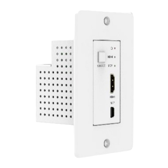
- Page 6 6. Operation Controls and Functions 6.1 Transmitter Panel Name Function Description The power LED indicator will illuminate in green Power LED when the product is powered on and red when the product is on standby. The green LED will be on when the HDMI input HDMI LED port is active and the HDMI signal is detected.
- Page 7 6.2 Receiver Panel Name Function Description HDMI output port, connect to HDMI display device HDMI OUT such as TV or Projector with an HDMI cable. Connect to the CAT6 OUT port on the transmitter CAT IN with a CAT cable. Power Indicator The power indicator lamp will be on when Lamp (Green)
- Page 8 7. Application Example HDMI and HDMI High-Definition Multimedia interface and the HDMI Logo are trademarks or registered trademarks of HDMI Licensing LLC in the United States and other countries. - 6 -...
Need help?
Do you have a question about the VLWP-DHC-TR and is the answer not in the manual?
Questions and answers