Table of Contents
Advertisement
Quick Links
Advertisement
Table of Contents

Related Manuals for VigilLink VLIP-JP4k3K


Summary of Contents for VigilLink VLIP-JP4k3K
- Page 1 VLIP-JP4k3K 4K60 over IP 1GbE with Video Wall Processing VER 1.1...
-
Page 2: Table Of Contents
Thank you for purchasing this product. Please read these instructions carefully for optimum performance and safety before connecting, operating, or adjusting this product. Please keep this manual for future reference. Surge protection device recommended. This product contains sensitive electrical components that electrical spikes may damage, surges, electric shocks, lightning strikes, etc. -
Page 3: Introduction
1. Introduction This product is based on JPEG2000 technology. It integrates the Copper port and Fiber port within a single box. Encoder input supports up to 4K60 4:4:4, audio embedding, or extracting. Decoder output supports up to 4K60 4:4:4 audio extracting. The product supports ARC/eARC/SPDIF/Analog audio return function, USB2.0/KVM/Camera, 1G Ethernet, bidirectional RS- 232, two-way IR, and PO function. -
Page 4: Package Contents
☆ Support POE function ☆ Built-in web page configuration and control, Telnet and SSH, as well ☆ HDMI audio formats: LPCM 2.0/5.1/7.1CH, Dolby Digital/Plus/EX, Dolby True HD, DTS, DTS-96/24, DTS-EX DSD, DTS High Res, DTS-HD Master ☆ Smart networking design for easy and flexible installation 3. -
Page 5: Specifications
4. Specifications Technical HDMI Compliant HDMI 2.0b HDCP Compliant HDCP 2.2 Video Bandwidth 18Gbps Video Compression JPEG2000 Standard Video Network Bandwidth Video Resolution Up to 4K@60Hz 4:4:4 Input: 8/10/12-bit Color Depth Output: 8-bit Color Space RGB 4:4:4, YCbCr 4:4:4 / 4:2:2 / 4:2:0 LPCM 2.0/5.1/7.1CH, Dolby Digital/Plus/EX, Dolby True HD, DTS, DTS-96/24, DTS-EX DSD, DTS High Res, DTS-HD HDMI Audio Formats... - Page 6 Input: 1 x SPDIF IN [Optical audio connector] 1 x L/R AUDIO IN [3-pin 3.81mm Phoenix connector] Output: 1 x HDMI OUT [Type A, 19-pin female] 1 x L/R AUDIO OUT [3-pin 3.81mm Phoenix connector] Control: 1 x RS-232 [3.81mm Phoenix connector] 1 x LAN (POE) [RJ45 jack] Decoder 1 x FIBER [Optical fiber slot]...
-
Page 7: Operation Controls And Functions
5. Operation Controls and Functions 5.1 Encoder Panel Name Function Description After powering on the device, press and hold the RESET button until the POWER LED and LINK LED flash RESET simultaneously; release the button to reset the device to factory settings. - Page 8 IR signal input port. The IR level can be set to 5V or 12V IR IN (default) through the panel buttons. VCC: Power output (12V or 5V configurable), maximum to 12V @50mA, 5V@ 100mA loading. The default output is 12V. RELAYS: 2 channel low-voltage relay ports, each group is independent and isolated, maximum to 1A 30VDC loading.
- Page 9 Connect with an optical fiber module, and transmit signals to the FIBER Decoder with an optical fiber cable directly or through a Switch. 7/25...
- Page 10 1G LAN port, connect network Switch to form a distributed system. LAN (POE) Note: The DC 12V adapter doesn't need to apply to the unit when the network switch delivers the POE power supply. Data Signal ▪ Light flashing: There is data transmission. Indicator lamp ▪...
- Page 11 EDID ID EDID Description EDID ID EDID Description 1080P_Stereo_Audio_2.0_SDR 4K2K60_420_Stereo_Audio_2.0_SDR 1080P_DolbyDTS_5.1_SDR 4K2K60_420_DolbyDTS_5.1_SDR 1080P_HD_Audio_7.1_SDR 4K2K60_420_HD_Audio_7.1_SDR 1080I_Stereo_Audio_2.0_SDR 4K2K60_444_Stereo_Audio_2.0_SDR 1080I_DolbyDTS_5.1_SDR 4K2K60_444_DolbyDTS_5.1_SDR 1080I_HD_Audio_7.1_SDR 4K2K60_444_HD_Audio_7.1_SDR 3D_Stereo_Audio_2.0_SDR 4K2K60_444_Stereo_Audio_2.0_HDR_10-bit 4K2K60_444_DolbyDTS_5.1_HDR_10-bit 3D_DolbyDTS_5.1_SDR 3D_HD_Audio_7.1_SDR 4K2K60_444_HD_Audio_7.1_HDR_10-bit 4K2K30_444_Stereo_Audio_2.0_SDR DVI_1280x1024 DVI_1920x1080 4K2K30_444_DolbyDTS_5.1_SDR 4K2K30_444_HD_Audio_7.1_SDR DVI_1920x1200 6, IR mode settings: After entering the configuration mode, press the UP/DOWN button to enter the third page with “IR2”...
-
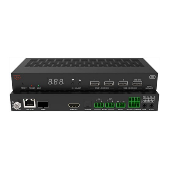
Page 12: Decoder Panel
(3) When using ARC, the ARC audio amplifier on the Encoder HDMI IN port and ARC TV on the Decoder HDMI OUT port should be used. When using eARC, the eARC audio amplifier on the Encoder HDMI IN port and eARC TV on the Decoder HDMI OUT port should be used. - Page 13 Connection status LED. ▪ Light on Encoder and Decoder are connected through the LAN(POE)/FIBER ports, and video signal is transmitted from the Encoder. LINK LED ▪ Light flashes: Encoder and Decoder are connected through the (Green) LAN(POE)/FIBER ports, but no video signal is transmitted from the Encoder.
- Page 14 RS-232 serial port, supporting RS-232 command pass-through RS-232 and local serial port control. AUDIO IN: Analog audio input port, the audio can be transmitted to Encoder AUDIO OUT in unicast mode (point-to-point direct connection). AUDIO IN/OUT AUDIO OUT: Analog audio output port. It outputs the same audio as that on HDMI OUT in case the audio format is LPCM.
- Page 15 Operation description of the LED screen and CH SELECT buttons (For Decoder). 1, ENC connection: After the system is powered on, the Decoder’s LED screen will show 000 by default if not set. Directly press the UP/DOWN button to select the channel ID of the connected Encoder (ID range: 000~767) to complete the connection.
- Page 16 6, IR mode settings: After entering the configuration mode, press the UP/DOWN button to enter the third page with “IR2” (in which “IR” refers to IR and “2” to 12V) displayed on the LED screen. Press and hold the UP + DOWN buttons for 5 seconds, then release them to enter the IR mode settings mode, in which the IR mode (IR1 or IR2) on the LED screen will flash at 1Hz, then press the UP/DOWN button to select the IR mode, then press and hold UP + DOWN buttons for 5 seconds to confirm the setting...
- Page 17 you do not perform any operation within 5 seconds. 15/25...
-
Page 18: Ir Pin Definition
5.3 IR Pin Definition 6. Rack Mounting Instruction 6.1 6U V2 Rack Mounting This product can be mounted in a standard 6U V2 rack (Please contact your supplier for a 6U V2 rack sale). The mounting steps are as follows: Step 1: Use included screws to fix two mounting ears on the product, as shown in the figure below: 16/25... - Page 19 Step 2: Insert the product with mounting ears into a 6U V2 rack (6/8/10 units can be installed vertically), as shown in the figure below: Step 3: Use screws to fix mounting ears on the rack to complete the mounting, as shown in the figure below: 17/25...
-
Page 20: V2 Rack Mounting
6.2 1U V2 Rack Mounting This product also can be mounted in a standard 1U V2 rack (2 units can be installed horizontally). The mounting steps are as follows: Step 1: Use included screws to fix two 1U V2 rack brackets on two products respectively, as shown in the figure below: Step 2: Use screws to fix two 1U V2 rack brackets together, as shown in the figure below:... -
Page 21: Mjpeg Substream Operation Introduction
7. MJPEG Substream Operation Introduction 7.1 MJPEG Substream Preview/Configuration via Web Page The product supports playing MJPEG Substream on the computer through the corresponding software, such as VLC media player; simultaneously, you can access the Web page to configure the MJPEG Substream. Follow the steps below to preview and configure the MJPEG Substream. - Page 22 Note: (1) The window in the lower left corner displays the Host names of all devices in the current network. (2) The window in the lower right corner displays the device's hostname, IP address, and Port number. (3) The Host name of the Encoder starts with AST-ENC; the Host name of the Decoder starts with AST-DEC.
- Page 23 Step 3: Set the PC’s IP address to the same network segment as the Encoder/Decoder IP address found in step 2. 21/25...
- Page 24 Step 4: According to the IP address of the Encoder/Decoder found through the bonjour protocol checking tool, input “http://IP:PORT/?action=stream” into the web browser on your PC. The MJPEG Substream will be displayed with the default resolution, as shown in the figure below. Step 5: Change the resolution of the obtained Encoder/Decoder IP address in the following format.
- Page 25 by returning the 0-size file. 23/25...
-
Page 26: Vlc Media Player Instruction
After changing, input the new Encoder/Decoder IP address into the web browser on the PC, and the MJPEG Substream will be displayed with the desired resolution, as shown in the figure below. 7.2 VLC Media Player Instruction First, perform steps 1~3, described in Chapter 7.1, then open the VLC media player on the PC. - Page 27 Click “Media > Open Network Stream.” After clicking the “Open Network Stream” option, the following page will appear. 25/25...
- Page 28 Enter the MJPEG Substream network URL, then click the “Play” button. Choose “Tools>Codec information”; a pop-up window will display and show you Stream information, as shown in the figure below. 26/25...
-
Page 29: Switch Model
Choose “Tools>Codec information>Statistics” to check the current Bitrate. Please see the following picture. Note: The Bitrate is floating up and down when you check it. This is a normal phenomenon. 8. Switch Model A network Switch used to set up the system should support below features: 1. -
Page 30: K Over Ip System Control
9. 4K over IP System Control Controller Box or third-party controller can control this product. For details of 4K over IP system control, please refer to the “Video over IP Controller” user manual. 10. Application Example 28/25... - Page 31 Note: (1) For the default IP mode of the Control LAN port of the Controller Box is DHCP, the PC also needs to be set to the “Obtain an IP address automatically” method, and a DHCP server (e.g., network router) is required in the system.
Need help?
Do you have a question about the VLIP-JP4k3K and is the answer not in the manual?
Questions and answers