Table of Contents
Advertisement
Quick Links
2940 AIR ADJUST RESIDUE MANAGER
*Patented
YETTER MANUFACTURING CO.
FOUNDED 1930
Colchester, IL 62326-0358
Toll free: 800/447-5777
309/776-3222 (Fax)
Website:
www.yetterco.com
E-mail:
info@yetterco.com
serviceteam@yetterco.com
GERMINATE UNIFORMITY ™
OPERATOR'S MANUAL
PART IDENTIFICATION
2565-983_REV_B ● 09/2021
Advertisement
Table of Contents

Related Manuals for Yetter GERMINATE UNIFORMITY 2940


Summary of Contents for Yetter GERMINATE UNIFORMITY 2940
- Page 1 2940 AIR ADJUST RESIDUE MANAGER OPERATOR’S MANUAL PART IDENTIFICATION 2565-983_REV_B ● 09/2021 *Patented YETTER MANUFACTURING CO. FOUNDED 1930 Colchester, IL 62326-0358 Toll free: 800/447-5777 309/776-3222 (Fax) Website: www.yetterco.com E-mail: info@yetterco.com serviceteam@yetterco.com GERMINATE UNIFORMITY ™...
-
Page 2: Table Of Contents
Tablet Mount / Power Harness ........………..…...….24 2940-103A Control Box Installation………………………………….……..25 2940-415 Water Separator/Regulator Assembly Installation………....25 ISOBUS Installation..................26 Yetter Compressor Installation…....…………..……..…..27 – 30 Compressor to Control Box Airline Installation…………………………….31 – 32 Airline Installation..................32 – 47 Operation………………………………………………………………………48 – 54 Maintenance………………………………………………………………..55 – 56 Parts Identification…………………………………………………....57 –... - Page 3 For our part, we want to welcome you to the group and thank you for buying a Yetter product. It is the responsibility of the user to read the operator’s manual and comply with the safe and...
- Page 4 Yetter Manufacturing warrants all products manufactured and sold by it against defects in material. This warranty being expressly limited to replacement at the factory of such parts or products as shall appear to be defective after inspection. This warranty does not obligate the Company to bear cost of labor in replacement of parts.
-
Page 5: Safety
SAFETY A brief description of signal words that may be used in this manual: CAUTION: Used as a general reminder of good safety practices or to direct attention to unsafe practices. WARNING: Denotes a specific potential hazard. DANGER: Denotes the most serious specific potential hazard. SAFETY PRECAUTIONS You can make your farm a safer place to live and work if you observe the safety precautions given. -
Page 6: Hydraulic Fittings Chart
Hydraulic Fittings Identification Chart -Due to common threads, mismatching can happen and could result in leaks and pressure loss -Be sure to verify which style and use dash sizes when ordering replacement parts Thread Styles -NPT is easily recognizable as tapered National Pipe Thread. It is not recommended for hydraulic systems but does exist on some agriculture equipment. - Page 7 2940-653 JCA Thrasher Module--------------------------------- ------------------2940-111 RAM Tablet Mount Kit 2940-114 Stand Alone Comp Control Kit---------------------- 2940-123A Hydraulic Manual Kit (Yetter Monitor) 2940-126A Pneumatic Combo Sub-Assembly (2940-010A) Mounting Bolt Bag – 2940-007A & 2940-010A 2940-128 2940-130A Pneumatic Combo Sub-Assembly (2940-007A) 2940-142 Mounting Bolt Bag-2940-001A, 002A, 005A, &...
- Page 8 Components, Kits, Accessories, & Ordering Numbers -----------------2940-151 10 ft. Main Power Cable Extension 2940-153A IGN/GRD Supply Harness, 15ft---------------- ------------------2940-154 (Used on Stand Alone Compressor Only) 30 ft. Dump Valve Harness Black 2940-163 20 ft Main Power Extension--------------------- ------------------2940-164A 5 ft. AUX to Air Harness 2940-165A 10 ft.
- Page 9 Components, Kits, Accessories, & Ordering Numbers PQE Inlet Elbow ¼ NPT to 3/8PTC---------- 2940-379 ------------------2940-380 3/8PTC X 1/8BSPP O-ring Straight Fitting 3/8PTC X 1/8BSPP O-ring Elbow Fitting--- 2940-381 ------------------2940-382 Shop Air Adapter 2940-383 3/8 PC WYE Fitting------------------------------- ------------------2940-386 Shorter Air Bag 2940-388 Larger Air Bag-------------------------------------...
- Page 10 Control Box ISOBUS Harness------------------ -------------------2940-656 ISOBUS Hitch Harness 2940-657 ISOBUS Extension Harness, 15ft-------------- 2940-658 ISOBUS Extension Harness, 30ft -------------------2940-659 JD ISOBUS Adapter Harness 2940-660 Terminator Harness----------------------------------- -------------------2940-661 Ag Leader Harness, Yetter Control Box 2940-662 Ag Leader Harness, Planter Control Module-----...
- Page 11 & tapping it, exposed side down. This will empty the pleats of filter of collected dust. If dust has been wet or will not clean out, call Yetter to order a new element, part # 2940-549 for hyd. compressors & 2940-395 for electric compressors, or if using an OEM hydraulic compressor, call your local dealer.
- Page 12 Tablet size is used, sourcing a larger RAM Tablet Mount will be necessary. RAM-HOL-UN11U can be purchased online for tablets 11 – 12”. Go into the tablets App Store, search for Yetter Air Adjust, & download the App. Once the system is installed, turn the key to make sure the 2940-653 Thrasher module’s indicator lights come on.
- Page 13 75psi of clean, dry air. The ‘clean, dry air’ is a key component of the air supply, moisture within the air supply can shorten the life cycle of the system. Yetter compressors should build to 145psi on the tank gauge before shutting off. When pressure in the tank drops below 120psi, the compressor will engage to build back up to 145psi.
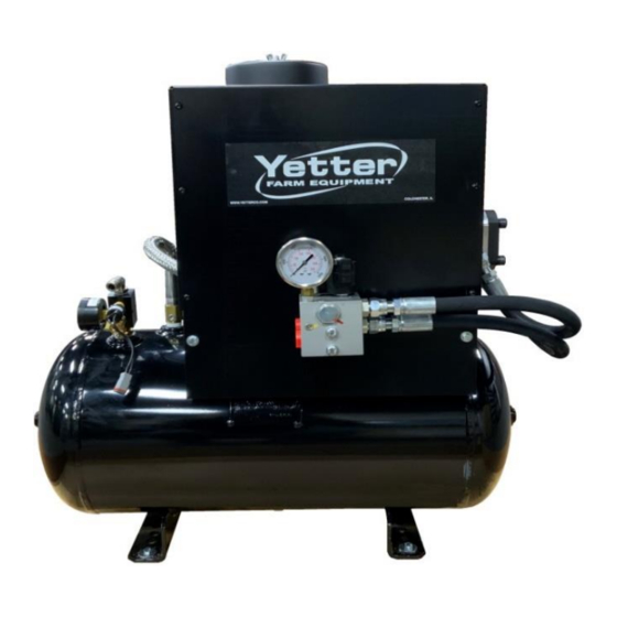
- Page 14 Hydraulic Compressor External Diagram Item Part Number Description Quantity 2940-549 Air Filter Compressor Pressure Line 2940-635 Output Elbow Fitting 3/8PTC 90 Degree 3/8NPT 2940-439 Tank Pressure Gauge Tank, 12 Gallon 2940-416 Safety Relief Valve Pressure Switch, 125PSI – 145PSI 2940-377 Hydraulic Pressure Port -6 ORFS Hydraulic Return to Tank Inlet Port -6 ORFS 2940-546...
- Page 15 (20FT) &/or 2940-189 (10FT) extension harnesses to reach the control box & install into this port. Used only if application uses a Yetter Hydraulic Compressor. (see page 28) POWER HARNESS CONNECTION - Depending on application, route 2940-164A or 2940-165A AUX PWR cable from rear of the tractor to this female connector.
- Page 16 2940-103A Control Box Internal Lay Out 2940-112A MIDAC MODULE 2940-637 2940-640 INTERIOR HARNESS (MOUNTED TO BACK WALL VALVE ASSEMBLY MAC BV VALVE (NO PART #) 2940-441A PRESSURE 2940-652 TRANSDUCER 12 X 14 X 8 (TANK SUPPLY) ENCLOSURE 2940-647 2940-642 ¼”NPT X 5/32PC 10-32 X RUN TEE 5/32PC...
- Page 17 & in harnesses at hinge points. Check all electrical connections, cables, & airline making sure nothing was damaged. Next, with the tractor on, connect to the WiFi with your tablet or pull the Yetter screen up on the ISOBUS VT, & press the ACTIVE SYSTEM icon. The compressor will turn on, build to 145psi (100-120psi on the cab controller) &...
-
Page 18: Installation Guide
& in harnesses at hinge points. Check all electrical connections, cables, & airline making sure nothing was damaged. Next, with the tractor on, connect to the WiFi with your tablet or pull the Yetter screen up on the ISOBUS VT, & press the ACTIVE SYSTEM icon. The compressor will turn on, build to 145psi (100-120psi on the cab controller) &... - Page 19 & in harnesses at hinge points. Check all electrical connections, cables, & airline making sure nothing was damaged. Next, with the tractor on, connect to the WiFi with your tablet or pull the Yetter screen up on the ISOBUS VT, & press the ACTIVE SYSTEM icon. The compressor will turn on, build to 145psi (100-120psi on the cab controller) &...
- Page 20 & in harnesses at hinge points. Check all electrical connections, cables, & airline making sure nothing was damaged. Next, with the tractor on, connect to the WiFi with your tablet or pull the Yetter screen up on the ISOBUS VT, & press the ACTIVE SYSTEM icon. The compressor will turn on, build to 145psi (100-120psi on the cab controller) &...
- Page 21 Residue Manager(RM) Installation ENGAGE THE CYLINDER STOPS ON THE PLANTER LIFT WHEELS TO “LOCK” THE PLANTER IN THE UP POSITION Installation overview: Prior to installation of each RM mounting bracket assembly, check the freedom of motion of the parallel linkage or pivot arm. ...
- Page 22 Residue Manager(RM) Installation Con’t For Case Models Installing RM Only Step 1: 800 – 1200 SERIES: Place 1) Pneumatic RM Assembly (2940-190A), 1) CNH Adaptor Bracket (2940-209), 1) CNH Mounting Bolt Bag (2940-145), 1) Wheel Mount (2940-215/2940-216), 1) Cyclo Stop Casting Bolt Bag (2965-135), 1) RH Wheel Assembly (2966-140), 1) LH Wheel Assembly (2966-141), &...
-
Page 23: Residue Manager Installation
Residue Manager Installation Con’t Step 3: Install the Wheel Mount (2940-215 or 2940-216) on the adjustment tube of the mounting bracket assembly. Recommended mounting location is 5 hole down from the top of the adjustment tube mounts to the top hole of the wheel mount. - Page 24 RM/Coulter Combo Installation Step 1: Place 1) RM/ Coulter Combo assembly (2940-126A or 2940-130A), 1) Coulter Blade, 1) Mounting Bolt Bag (2940-128), 1) RH wheel assembly (2966-116), & 1) LH wheel assembly (2966-117) at each row unit. Mount the RM/Coulter Combo assembly to the row unit face plate using 3) ½”...
- Page 25 Tablet, Switched Power, & Main Power Installation *Skip steps 1 & 2 if using ISOBUS monitor* Step 1: Begin installing the 2940-111 once an adequate mounting location has been found. Fix the base component of the 2940-111 Mounting Bracket in place to the back of the Tablet Holder using 4 – screws (A). Use items labeled B if mounting to a slotted, flat mounting system &...
-
Page 26: 2940-103A Control Box Installation
2940 Air Adjust System. In some situations, a mount may need to be built to install the 2940-103A in an adequate location. OEM ELECTRIC COMPRESSORS ALREADY ONBOARD PLANTERS WILL NOT OPERATE YETTER 2940 AIR ADJUST SYSTEMS! NOTE: THE IMAGES BELOW CONTAIN THE 2940-103 CONTROL BOX MANUFACTURED FROM 2013 -2020. -
Page 27: Isobus Installation
ISOBUS Installation – To Tractor Hitch Connector Step 1: Install 2940-655 Yetter ISOBUS Y Harness at Yetter Control Box. Install triangular 3 pin connector on the 2940-655 to triangular 3 pin connector on the 2940-654 Yetter Control Harness. Step 2: Install 2940-657 (15ft) or 2940-658 (30ft) extension harnesses to 2940-655 &... -
Page 28: Yetter Compressor Installation
& 2-point top link. Yetter has 4 different mounting kits; 2940-085 to mount compressor to top link of the 2 point hitch, 2940- 086 to mount to draft tube, 2940-090 to mount to an 8”... - Page 29 Yetter Electric Compressor Installation Step 3: On electric compressor installation, install the 2940-150 on the tractor battery. Red cable connects to positive battery post & black cable connects to negative battery post. Install the 2940-151 (10ft) & 2940-163 (20ft) main power extensions until you reach the compressor.
- Page 30 & the JIC end faces downward. Install 1) 2515-831 3/8 – 6 10ft hydraulic hose to that fitting. Control Box to Yetter Compressor Wiring Installation Step 1: Install the 2940-181 Solenoid/Pressure Switch Control Harness on the compressor.
- Page 31 Step 6: Connect the hydraulic hose attached to case drain on the motor to case drain connector on the tractor or by teeing into a case drain circuit on the planter. Below are a few examples of hydraulic connection. The Yetter hydraulic compressor is equipped with a case drain port on the motor.
- Page 32 Step 2: Connect the 2940-189 (10ft) control harness to 4 pin connector of the 2940-181 & route to control box. If more length is needed, call Yetter & order more. (2940-182 is 20ft length; 2940-189 is 10ft length) Step 3: Connect the 2940-182 or 2940-189 into the 4 pin female connector on side of the control box.
- Page 33 (as indicated by arrow below) Step 2: Install 2940-367 250psi rated 3/8” airline from the installed Tee to the inlet (labeled A) of the Yetter water separator. Step 3: Install 2940-345 3/8” black airline from outlet port (labeled B) on water separator to inlet port (labeled 1) on control box.
- Page 34 (Blue Airline) and down pressure (Black Airline) on the planter for troubleshooting & leak detection indication. Route the airlines as efficiently and conveniently as possible. If there is no diagram for your situation, contact a Yetter service representative (800-447-5777) and a drawing will be made.
- Page 35 6 Row Airline Diagram 6/11 or 6/12 Split Row Airline Diagram...
- Page 36 8 Row Airline Diagram 8/15 & 8/16 Split Row Airline Diagram...
- Page 37 12 Row Airline Diagram...
- Page 38 12/23 & 12/24 Split Row Airline Diagram Step 1: T1 & T2 Route black & blue airline from corn row 1 to corn row 4. At corn row 4, install the black airline into the down pressure air bag fitting & the blue airline in the up pressure air bag fitting.
- Page 39 16 Row Airline Diagram...
- Page 40 16/31 & 16/32 Split Row Airline Diagram...
- Page 41 16/31 & 16/32 Split Row Airline Diagram Con’t Step 1: T1 & T2 Route black & blue airline from corn row 1 to corn row 6. At corn row 6, install the black airline into the down pressure air bag fitting & the blue airline in the up pressure air bag fitting. Trace both airlines back to corn row 1, installing a tee in each airline at corn rows 2-5.
- Page 42 24 Row Airline Diagram...
- Page 43 24/47 & 24/48 Row Airline Diagram...
- Page 44 24/47 & 24/48 Row Airline Diagram Con’t Step 1: T1 & T2 Route black & blue airline from corn row 1 to corn row 10. At corn row 10, install the black airline into the down pressure air bag fitting & the blue airline in the up pressure air bag fitting. Trace both airlines back to corn row 1, installing a tee in each airline at corn rows 2-9.
- Page 45 32 Row Airline Diagram...
- Page 46 36 Row Airline Diagram...
- Page 47 48 Row Airline Diagram...
- Page 48 54 Row Airline Diagram...
- Page 49 1. SYSTEM PRESSURE/COMPRESSOR MONITORING Just to the left of the Yetter logo, you can monitor system pressure. If the system is below 75psi upon initial startup or below 50psi for more than 5 seconds during operation, the rectangle will turn red & system will not allow air to the row cleaner air bags.
- Page 50 The tolerance specs are +/- 7psi of the target pressure. If target is 30, actual is 35, that is within tolerance. ABOUT: This is info about the system & contact info for Yetter if any questions or service issues come up.
- Page 51 AIR ADJUST. If using ISOBUS, the status 2 light will also illuminate. HIGH COMPRESSOR RUN TIME: If using a Yetter compressor, the system has a time limit that the compressor can run before timing out. If the compressor runs for 15 minutes without turning off via the pressure switch, this message will appear.
- Page 52 Step 3: If using Yetter compressor, the compressor should engage (apply hydraulic flow if applicable) to build 145psi & shut off. If 145psi isn’t reached, see page 53 to make an adjustment to the flow control valve. If Yetter compressor doesn’t run & is below 125psi, check the 40A breaker (&...
-
Page 53: Operation
IMPORTANT: Failure to properly set the planter frame height & levelness can result in less than successful operation of the planter & the Yetter product. This may result in damaged equipment. All operators should read & thoroughly understand the instructions given prior to using the Yetter product. - Page 54 OPERATION PRECAUTIONS To ensure the hydraulic compressor motor doesn’t exceed recommended operating RPM level, the hydraulic oil flow control valve has been preset. In some instances, the compressor may run below optimum rpm, or will not reach 145psi of tank pressure read at the gauge on the compressor tank causing the VDM to think the compressor is running continuously.
- Page 55 SYSTEM LEAK TESTING: Step 1: Power the Yetter control box, connect tablet to “AIR ADJUST” WiFi & open Yetter app or if ISOUBS application, open Yetter run page on the ISOBUS VT, & press ACTIVATE SYSTEM. If using planters onboard compressor, make sure the compressor has run 1 complete cycle, and shut off to make sure there are no leaks at compressor &...
- Page 56 The compressor is shipped empty of pump lubrication and needs oil added before operation. Provided is a 1 Liter bottle of grade 111 full synthetic. Add oil until oil level is seen half way up on the sight glass & then recheck oil level on the dipstick. Yetter part number for purchasing new bottle is 2940-550. GUARDS: Always ensure the housing and guards are in place during operation.
-
Page 57: Maintenance
Yetter Hydraulic Compressor Maintenance Remove housing to add or fill the pump with oil. See page 27 for housing removal instructions. 2940-103A Control Box Maintenance Daily when used – clean dirt/debris from inside of box, inspect all parts for damage/leaks & replace as needed. -
Page 58: Parts Identification
AIR BAG REPLACEMENT 6” AIR BAG 8” AIR BAG 2940-386 2940-388 PARTS IDENTIFICATION 2940-049A (For John Deere Planters with Heavy Duty Double Disc Scrapers) Item Part Number Description 2502-294 1/2-13 x 1-1/2 HHCS GR 5 ZP 2520-357 ½-13 HEX LOCK NUT ZP 2526-355 ½... - Page 59 R.M. MOUNT PLATE W.A. 2940-309 UPFORCE TOP MOUNT 2940-340 AIR BAG CAP PLUG 2940-386 SHORTER AIR BAG 2940-388 LARGER AIR BAG 2940-472 BUSHING 2940-473 BUSHING 2940-474 BUSHING .750” OD X .406” ID X 2.630” BUSHING 2940-478 2940-590 YETTER VERTICAL DECAL...
- Page 60 R.M. MOUNT PLATE W.A. 2940-309 UPFORCE TOP MOUNT 2940-340 AIR BAG CAP PLUG 2940-386 SHORTER AIR BAG 2940-388 LARGER AIR BAG 2940-472 BUSHING 2940-473 BUSHING 2940-474 BUSHING .750” OD X .406” ID X 2.630” BUSHING 2940-478 2940-590 YETTER VERTICAL DECAL...
- Page 61 2940-001B & 2940-002B PARTS IDENTIFICATION Item Part Number Description 2502-246 3/8-16 X 3 HHCS GR5 ZP 2502-294 ½-13 X 1 ½ HHCS GR5 ZP 2502-351 ½-13 X 2 HHCS GR 5 ZP (MOUNTING TO AGCO 9000) 2520-255 3/8-16 LOCK HEX NUT, GR A, ZP 2520-357 ½-13 LOCK HEX NUT, GR A, ZP 2520-452...
- Page 62 2940-003B & 2940-004B PARTS IDENTIFICATION Item Part Number Description 3/8 – 16 X 1 – ¼ HHCS GR 5 ZP (FOR CYCLO STOP CASTING) 2502-244 2502-293 1/2-13 X 1-1/4 HHCS GR5 ZP (FOR CYCLO STOP CASTING) 2502-246 3/8-16 X 3 HHCS GR5 ZP 2502-293 ½-13 X 1 1/4 HHCS GR5 2502-294...
- Page 63 2940-005B & 006B PARTS IDENTIFICATION Item Part Number Description 2502-246 3/8-16 X 3 HHCS GR5 ZP 2502-294 ½-13 X 1 ½ HHCS GR5 ZP 2502-351 ½-13 X 2 HHCS GR5 ZP 2520-255 3/8-16 LOCK NUT, GR A, ZP 2520-357 ½-13 LOCK HEX NUT, GR A, ZP 2520-452 5/8-11 HEX NUT ZP 2525-451...
- Page 64 2940-571 HOSE, LH COMBO 2940 AIR SYSTEMS 2940-572 HOSE, RH COMBO 2940 AIR SYSTEMS 2940-577 ZIP TIE 2940-589 YETTER HORIZONTAL DECAL 1” X 3” 2940-609 3/8 PC X 1/8 BSPP O-RING 2967-613 TITAN PIN, JD ZP 2967-630 SCRAPER, RH 2967-631...
- Page 65 2940-571 HOSE, LH COMBO 2940 AIR SYSTEMS 2940-572 HOSE, RH COMBO 2940 AIR SYSTEMS 2940-577 ZIP TIE 2940-589 YETTER HORIZONTAL DECAL 1” X 3” 2940-609 3/8 PC X 1/8 BSPP O-RING 2967-613 TITAN PIN, JD ZP 2967-630 SCRAPER, RH 2967-631...
- Page 66 2940-007B PARTS IDENTIFICATION Item Part Number Description 2502-293 ½-13 X 1 ¼ HHCS GR 5 ZP 2502-294 ½-13 X 1 ½ HHCS GR 5 ZP 2502-351 ½-13 X 2 HHCS GR 5 ZP (FOR MOUNTING TO AGCO 9000) 2520-361 ½-13 FLANGE WHIZLOCK HEX NUT GR 5 ZP 2520-362 ½-13 HEX LOCK NUT GR C ZP 2520-464...
- Page 67 2940-010B PARTS IDENTIFICATION JD 1700-7200 AGCO 9000 Item Part Number Description 2502-293 ½-13 X 1 ¼ HHCS GR 5 ZP 2502-294 ½-13 X 1 ½ HHCS GR 5 ZP 2502-351 ½-13 X 2 HHCS GR 5 ZP (FOR MOUNTING TO AGCO 9000) 2520-361 ½-13 FLANGE WHIZLOCK HEX NUT GR 5 ZP 2520-362...
- Page 68 PARTS IDENTIFICATION 2966-140-ST-FW RIGHT HAND SHARK TOOTH WHEEL ASSEMBLY 2966-140-ST-FW LEFT HAND SHARK TOOTH WHEEL ASSEMBLY...
- Page 69 PARTS IDENTIFICATION 2966-140-FW RIGHT HAND TAPER TOOTH WHEEL ASSEMBLY 2966-141-FW LEFT HAND TAPER TOOTH WHEEL ASSEMBLY...
- Page 70 PARTS IDENTIFICATION 2966-140-BW-FW RIGHT HAND BEVEL WHEEL ASSEMBLY 2966-141-BW-FW LEFTT HAND BEVEL WHEEL ASSEMBLY...
- Page 71 PARTS IDENTIFICATION 2966-117-BW-FW BEVEL WHEEL LEFT HAND (SHOWN) 2966-117-ST-FW SHARK TOOTH WHEEL 2966-117-FW TAPER TOOTH WHEEL 2966-116-BW-FW BEVEL WHEEL RIGHT HAND 2966-116-ST-FW SHARK TOOTH 2966-116-FW TAPER TOOTH WHEEL Item Part Number Description 2502-220 5/16-18 X ¾ HHFS 2502-222 5/16-18 X 1-1/4 HHFS 2570-994 PLUG (BEVEL WHEEL ONLY) 13”...
- Page 72 PARTS IDENTIFICATION Item Part Number Description 2565-162 YETTER DECAL, 1 ½ X 4 ½ 2940-121 ASSEMBLY, COULTER HUB 2940-232 FACEPLATE W.A., JD 7000, AGCO 6000 & 8000, KINZE Item Part Number Description 2565-162 YETTER DECAL, 1 ½ X 4 ½...
- Page 73 PARTS IDENTIFICATION Item Part Number Description 2502-383 M16 X 2 X 80 HEX HEAD BOLT 2515-839 SEAL, COULTER 2515-840 SEAL, WHELL BEARING CUP M16 X 2 – 6H LOCK NUT CLASS 10.9 ZP 2520-475 1” – 14 CASTLE NUT 2520-569 2526-581 M26 X 44 X 4 ROUND WASHER ZN 2526-583...
- Page 74 PARTS IDENTIFICATION Item Part Number Description 2502-198 5/16-18 X 1 HHCS GR 5 ZP 2502-398 5/8-11 X 9 ½ HHCS GR 5 ZP 2520-205 5/16-18 LOCK HEX NUT ZP 2520-459 5/8-11 LOCK HEX NUT ZP 2940-479 ANGLE MOUNT BRACKET Item Part Number Description 2502-198 5/16-18 X 1 HHCS GR 5 ZP...
- Page 75 Item Part Number Description 2502-294 ½-13 X 1 ½ HHCS GR 5 ZP 2502-373 ½-13 X 6 HHCS GR 5 ZP 2520-352 ½-13 HEX NUT ZP 2520-357 ½-13 LOCK HEX NUT ZP 2525-352 ½ MED LOCK WASHER ZP 2526-352 ½ SAE FLAT WASHER ZP 2940-207 COMPRESSOR MOUNT W.A., LH 2940-208...
- Page 76 PARTS IDENTIFICATION Item Part Number Description 2502-294 11 ½-13 X 1 ½ HHCS GR 5 ZP 2502-349 11 ½-13 X 5 FLTHD HHCS GR 5 ZP 2520-352 ½ ½-13 HEX NUT ZP 2525-352 ½ MED LOCK WASHER ZP 2526-351 ½ STANDARD FLAT WASHER ZP 2940-344 COMPRESSOR STRAP 2940-351...
- Page 77 RUBBER SPIDER INSERT FOR LOVEJOY COUPLER 2940-554 HYDRAULIC MOTOR HOUSING COVER MOTOR ELBOW FITTING INLET ELBOW FITTING 2940-519A HYDRAULIC COMPRESSOR FAN, CAST (will fit on all Yetter Hyd. Compressors) 2940-549 HYDRAULIC COMPRESSOR AIR FILTER (FILTER ELEMENT ONLY) FILTER ELBOW BACK GUARD AIR MANIFOLD 2940-416...
- Page 78 HYDRAULIC PUMP (2940-545) PARTS IDENTIFICATION PART REFERENCE ONLY...
- Page 79 2940-103A PARTS IDENTIFICATION PART # DESCRIPTION 1200-337 1/4 TUBING, 100FT ROLL, BLACK 2940-112A 12V MIDAC VDM 2940-345 3/8 TUBING, 100FT ROLL, BLACK 2940-376 WATER SEPARATOR DRAIN VALVE 2940-408 3/8PTC X 1/4NPT 90° ELBOW FITTING 2940-441A 0-200PSI PRESSURE TRANSDUCER W/ DEUTSCH 3/8”PTC X 3/8NPT 90°...
- Page 80 2940-101A PARTS IDENTIFICATION Item Part # Description 1 2940-416 175PSI TANK SAFETY RELIEF VALVE 2 2940-439 0-160PSI HYDRAULIC COMPRESSOR GAUGE AIR MANIFOLD 4 2940-635 3/8PC X 3/8NPT 90° ELBOW FITTING, SWIVEL 5 2940-336 HIGH PRESSURE RELIEF VALVE (NO FITTINGS) 1/4”PC TO 1/8NPT ELBOW 1200-323 6 2940-377 COMPRESSOR PRESSURE SWITCH 125-145PSI...
-
Page 81: Troubleshooting
Troubleshooting Guide Problem Cause Corrective Action Tank pressure drops when 1. improper check valve function 1. replace check valve on compressor compressor shuts off 2. loose connections/ air leak 2. perform leak check (see pages 53 & 54) 3. water separator drain valve 3. - Page 82 2565-983_REV_B ● 09/21...
Need help?
Do you have a question about the GERMINATE UNIFORMITY 2940 and is the answer not in the manual?
Questions and answers