Table of Contents
Advertisement
Quick Links
Download this manual
See also:
Set-up / Parts Manual
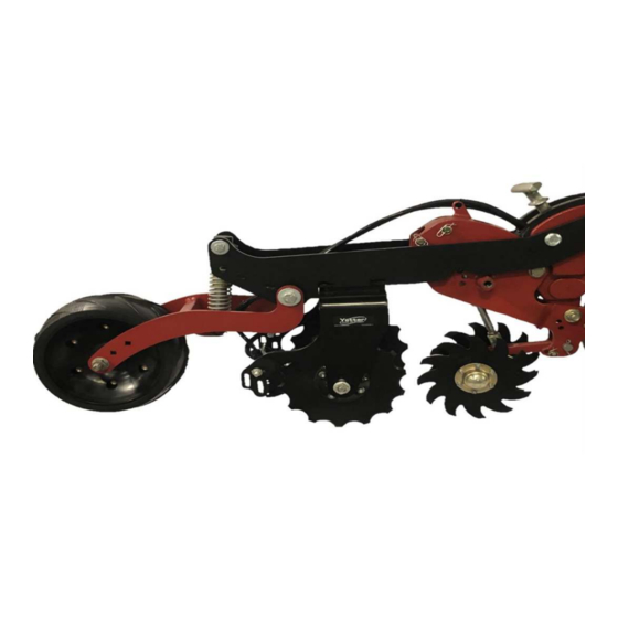
MODELS 2968-050 & 2968-052 – SINGLE WHEEL
MODELS 2968-051 & 2968-053 – DUAL WHEEL
YETTER MANUFACTURING CO.
FOUNDED 1930
Colchester, IL 62326-0358
Toll free: 800/447-5777
309/776-3222 (Fax)
Website: www.yetterco.com
E-mail:
info@yetterco.com
ROW UNIT MID-MOUNT
FERTILIZER INJECTION OPENER
CNH ROW UNITS
SET UP & PARTS MANUAL
2565-960 – 02/2019
Advertisement
Table of Contents

Related Manuals for Yetter 2968-050


Summary of Contents for Yetter 2968-050
- Page 1 ROW UNIT MID-MOUNT FERTILIZER INJECTION OPENER MODELS 2968-050 & 2968-052 – SINGLE WHEEL MODELS 2968-051 & 2968-053 – DUAL WHEEL CNH ROW UNITS SET UP & PARTS MANUAL 2565-960 – 02/2019 YETTER MANUFACTURING CO. FOUNDED 1930 Colchester, IL 62326-0358 Toll free: 800/447-5777 309/776-3222 (Fax) Website: www.yetterco.com...
-
Page 2: Table Of Contents
TABLE OF CONTENTS FOREWORD …………………………………………………..…....3 SAFETY …………………………………………………………...…....4 PICTORIAL PART LIST …………………...……………....5 – 10 INSTALLATION …………………………………………………... 10 – 16 OPERATION ..………..……..…...…………......16 – 17 MAINTENANCE ………..…..…………..………....18 – 20 PARTS IDENTIFICATION…...………………..……...….... 21 – 28 BOLT TORQUE Important: Over-tightening hardware can cause just as much damage as under-tightening. Tightening hardware beyond the recommended range can reduce its shock load capacity. -
Page 3: Foreword
WARRANTY Yetter Manufacturing warrants all products manufactured and sold by it against defects in material. This warranty being expressly limited to replacement at the factory of such parts or products as shall appear to be defective after inspection. This warranty does not obligate the Company to bear cost of labor in replacement of parts. -
Page 4: Safety
BE ALERT! YOUR SAFETY IS INVOLVED WATCH FOR THIS SYMBOL. IT POINTS OUT IMPORTANT SAFETY PRECAUTIONS. IT MEANS “ATTENTION – BE ALERT!” It is your responsibility as an owner, operator, or supervision to know and instruct everyone using this machine at the time of initial assignment and at least annually thereafter, of the proper operation, precautions, and work hazards which exist in the operation of the machine in accordance with OSHA regulations. -
Page 5: Pictorial Part List
2968-050 Pictorial Parts List For CNH 2000 Row Units, Single Disc, Left or Right Hand ONLY IF –LH ORDERED ONLY IF –RH ORDERED 2968-227 2968-150 2968-359-LH 2968-359-RH QTY 1 QTY 1 QTY 1 QTY 1 Bolt Bag Close Wheel Mount Short Fert. - Page 6 2968-054 Pictorial Parts List Box Mount Kit For CNH 1200 Row Units, Dual Disc 2502-807 2968-375 2520-477 2968-374 QTY 4 QTY 8 QTY 1 QTY 2 Box Mount Spacer M16X2X80 Bolt M16X2 Hex Nut Box Mount Bracket 2968-132 Pictorial Parts List – 10” Fertilizer Wheel Assembly 2965-352 2968-320 2570-740...
- Page 7 2968-113 Pictorial Parts List Bolt Bag for 2968-052 2505-207 – 5/16 – 18 X 1 ¾ CARRIAGE BOLT – QTY 4 2505-208 – 5/16 – 18 X 1 ½ CARRIAGE BOLT – QTY 4 2505-345 – ½ – 13 X 2 CARRIAGE BOLT – QTY 3 2515-846 -MALE CONNECTOR - 3/8 X 1/4 NPTF–...
- Page 8 2968-114 Pictorial Parts List Bolt Bag for 2968-053 2505-207 – 5/16 – 18 X 1 ¾ CARRIAGE BOLT – QTY 4 2505-208 – 5/16 – 18 X 1 ½ CARRIAGE BOLT – QTY 4 2505-343 – ½ – 13 X 2 ½ CARRIAGE BOLT – QTY 3 2505-345 –...
- Page 9 2968-149 Pictorial Parts List – Bolt Bag for 2968-051 2502-314 – 1/2-13 X 2-1/4" HHCS GR 5 ZYD – QTY 3 2502-333 –5/8 – 11 X 9 HHCS GR 5 ZP – QTY 1 2502-373 – ½ – 13 X 6 HHCS GR 5 ZP – QTY 1 2502-808 –...
- Page 10 2968-150 Pictorial Parts List – Bolt Bag for 2968-050 2502-317 – 1/2-13 X 1 ¾" HHCS GR 5 ZYD – QTY 3 2502-333 –5/8 – 11 X 9 HHCS GR 5 ZP – QTY 1 2502-373 – ½ – 13 X 6 HHCS GR 5 ZP – QTY 1 2502-808 –...
-
Page 11: Installation
INSTALLATION INSTRUCTIONS Step 1: Remove the items listed below that are part of the closing wheel assembly on the seeding unit. The closing discs will remain in the same location directly behind the gauge wheels. 1200 SERIES ROW UNIT 1 – SPRING PIN & CLIP 2 –... - Page 12 INSTALLATION INSTRUCTIONS Step 2: Attach the front of the Main Mount Bracket to each planter row unit. Attach the rear firming wheel & compression spring to the rear of the main mount bracket. On CNH 1200 row units, attach the closing wheel springs to the Main Mount Bracket. 1200 SERIES ROW UNIT 2100 SERIES ROW UNIT...
- Page 13 2968-050 & 2968-052 INSTALLATION INSTRUCTIONS SINGLE DISC PLACEMENT Step 3: Install the fertilizer wheel mount to the main mount bracket using 3) ½ X 2 ¼ bolts, 3) ½ flat washers, & 3) ½ lock nuts. Install each wheel assembly by placing a 5/8 flat washer over the D-Bolt, slide the D-Bolt through the hole to set the depth of the blade (see page 16 for depth chart), &...
- Page 14 2968-051 INSTALLATION INSTRUCTIONS DUAL DISC PLACEMENT Step 3: Install the fertilizer wheel mounts to the main mount bracket using 3) ½ X 2 ¼ bolts, 3) ½ flat washers, & 3) ½ lock nuts. install a 2968-051-L. On the seeding units where the left closing wheel is leading, On the seeding units where the right closing wheel is leading, install a 2968-051-R.
- Page 15 2968-053 INSTALLATION INSTRUCTIONS DUAL DISC PLACEMENT Step 3: Install the LH & RH 2968 arms to the main mount bracket using 3) ½ X 2 ½ carriage bolts, 3) ½ flat washers, & 3) ½ lock nuts. Install each wheel assembly by placing a 5/8 flat washer over the D-Bolt, slide the D-Bolt through the hole to set the depth of the blade (see page 16 for depth chart), &...
-
Page 16: Operation
INSTALLATION INSTRUCTIONS STEP 9: Assemble nozzle tip (not supplied) to each 2968-218 injector holder. Injector tips can be ordered through fertilizer equipment dealer. Calibrate the fertilizer pump and tips to maximum recommended pressure of 30PSI and minimum 20PSI at the tip. Attach the fertilizer hose to the top side of each coupler. OPERATION On dual fertilizer placement, the wheels are staggered front to back to keep the soil from heaving. -
Page 17: Operation
OPERATION LIQUID FERTILIZER APPLICATION RATE & PRESSURE CHART – TABLES BASED ON 30” NOZZLE SPACING GALLONS PER ACRE (USING WATER) TIP # LIQUID CAPACITY 1 NOZZLE 4 MPH 5 MPH 5.5 MPH 6 MPH 7 MPH 8MPH PRESSURE IN PSI IN GPM #00015 0.11... -
Page 18: Maintenance
MAINTENANCE IMPORTANT: If seal is removed from hub/bearing assembly, grease bearing Every 50 hours. If seal is left assembled, 2-3 pumps of grease twice a year, depending on acres, is sufficient. IMPORTANT: For proper operation, the planter frame must operate level (fore, aft &... -
Page 19: Maintenance
MAINTENANCE NOTE: BE CERTAIN TO ALIGN THE GREASE FITTING WITH THE SLOT IN THE WHEEL & HUBCAP SO THAT THE GREASE CAN FLOW FREELY. Grease must fill this Hubcap cavity. -
Page 20: Maintenance
Alternative Lubricants Conditions in certain geographical areas may require special lubricants & lubrication practices which do not appear in the operator’s manual. If there are any questions, consult Yetter Manufacturing Co. to obtain latest information & recommendation. PART #... - Page 21 2968-050-L PART IDENTIFICATION ITEM PART # DESCRIPTION 2502-317 ½ - 13 X 1 ¾ HHCS GR 5 ZP 2502-333 5/8 – 11 X 9 HHCS GR 5 ZP 2502-373 ½ - 13 X 6 HHCS GR 5 ZP 2502-808 M16 X 40 SERRATED HEX FLANGE BOLT ZP 2515-846 MALE CONNECTOR –...
- Page 22 2968-050-R PART IDENTIFICATION ITEM PART # DESCRIPTION 2502-317 ½ - 13 X 1 ¾ HHCS GR 5 ZP 2502-333 5/8 – 11 X 9 HHCS GR 5 ZP 2502-373 ½ - 13 X 6 HHCS GR 5 ZP 2502-808 M16 X 40 SERRATED HEX FLANGE BOLT ZP 2515-846 MALE CONNECTOR –...
- Page 23 ½ STANDARD FLAT WASHER ZP 2526-355 ½ FLAT WASHER HARDENED ZP 2526-451 5/8 STANDARD FLAT WASHER ZP 2526-454 5/8 SAE FLAT WASHER HARDENED ZP 2565-179 YETTER DECAL 2967-567 PIVOT BUSHING ZP 2968-218 INJECTOR HOLDER W.A. 2968-227 2968 MOUNT ASSEMBLY, CASE 2150 2968-359-LH...
- Page 24 ½ STANDARD FLAT WASHER ZP 2526-355 ½ FLAT WASHER HARDENED ZP 2526-451 5/8 STANDARD FLAT WASHER ZP 2526-454 5/8 SAE FLAT WASHER HARDENED ZP 2565-179 YETTER DECAL 2967-567 PIVOT BUSHING ZP 2968-218 INJECTOR HOLDER W.A. 2968-227 2968 MOUNT ASSEMBLY, CASE 2150 2968-359-RH...
- Page 25 3/8 MEDIUM LOCK WASHER ZP 2526-253 3/8 SAE FLAT WASHER ZP 2526-355 ½ FLAT WASHER HARDENED ZP 2526-454 5/8 SAE FLAT WASHER HARDENED ZP 2565-179 YETTER DECAL 2570-448 .120 BOWTIE LOCKING COTTER ZP 2968-218 INJECTOR HOLDER W.A. 2968-226 MAIN MOUNT BRACKET W.A. 2968-383...
- Page 26 3/8 MEDIUM LOCK WASHER ZP 2526-253 3/8 SAE FLAT WASHER ZP 2526-355 ½ FLAT WASHER HARDENED ZP 2526-454 5/8 SAE FLAT WASHER HARDENED ZP 2565-179 YETTER DECAL 2570-448 .120 BOWTIE LOCKING COTTER ZP 2968-218 INJECTOR HOLDER W.A. 2968-226 MAIN MOUNT BRACKET W.A. 2968-383...
-
Page 27: Parts Identification
3/8 MEDIUM LOCK WASHER ZP 2526-253 3/8 SAE FLAT WASHER ZP 2526-355 ½ FLAT WASHER HARDENED ZP 2526-454 5/8 SAE FLAT WASHER HARDENED ZP 2565-179 YETTER DECAL 2570-448 .120 BOWTIE LOCKING COTTER ZP 2968-218 INJECTOR HOLDER W.A. 2968-226 MAIN MOUNT BRACKET W.A. 2968-383... -
Page 28: Parts Identification
PARTS IDENTIFICATION 2968-132 (SHOWN) 10” WHEEL ASSEMBLY 2968-133 11” WHEEL ASSEMBLY ITEM PART # DESCRIPTION 2505-207 5/16 – 18 X 1 ¼ CARRIAGE BOLT GR 5 ZP 2520-206 5/16 – 18 FLANGE LOCK NUT 2570-740 D-BOLT, FLANGED, 5/8 – 11 X 2.812 GR 8 2965-128 HUB &... - Page 31 NOTES:...
- Page 32 2565-960 – 02/2019...
Need help?
Do you have a question about the 2968-050 and is the answer not in the manual?
Questions and answers