
Related Manuals for SCHUNK DPG-plus Series


Summary of Contents for SCHUNK DPG-plus Series
- Page 1 Translation of Original Operating Manual Assembly and Operating Manual DPG-plus Sealed 2-Finger Parallel Gripper...
- Page 2 Imprint Copyright: This manual is protected by copyright. The author is SCHUNK GmbH & Co. KG. All rights reserved. Any reproduction, processing, distribution (making available to third parties), translation or other usage - even excerpts - of the manual is especially prohibited and requires our written approval.
-
Page 3: Table Of Contents
Table of Contents Table of Contents General........................ 6 About this manual .................... 6 1.1.1 Presentation of Warning Labels ............... 7 1.1.2 Applicable documents ................ 7 1.1.3 Sizes ...................... 8 1.1.4 Variants..................... 8 Warranty ...................... 8 Scope of delivery .................... 9 Accessories ...................... 10 1.4.1 Sealing kits .................... 10 1.4.2 Spare parts packages ................ 11 Basic safety notes .................... 13 Intended use....................... - Page 4 Table of Contents Assembly ........................ 24 Installing and connecting.................. 24 Connections...................... 26 5.2.1 Mechanical connection................ 26 5.2.2 Pneumatic connection................ 28 Installing the ventilation connection/air purge connection ....... 30 Installing the sensors .................. 33 5.4.1 Overview of sensors ................ 33 5.4.2 Setting dimensions for magnetic switches .......... 34 5.4.3 Switch-off hysteresis for magnetic switches .......... 35 5.4.4 Mounting magnetic switch MMS 22............ 36 5.4.5 Mounting programmable magnetic switch MMS 22-PI1...... 37...
- Page 5 Table of Contents Assembly device cylinder piston with gripping force maintenance .... 63 7.7.1 Sizes 40 - 100 .................. 63 7.7.2 Sizes 125 - 380 .................. 64 Assembly drawing (previous version).............. 65 7.8.1 Assembly of variants OD / ID / without maintenance of gripping force.. 66 7.8.2 Assembly of the variant with force amplification cylinder ......
-
Page 6: General
General 1 General 1.1 About this manual This manual contains important information for a safe and appropriate use of the product. This manual is an integral part of the product and must be kept accessible for the personnel at all times. Before starting work, the personnel must have read and understood this operating manual. -
Page 7: Presentation Of Warning Labels
• Assembly and operating manuals of the accessories * • For ATEX versions: Supplementary sheet "Installation and operating instructions - EX" * The documents marked with an asterisk (*) can be downloaded on our homepage schunk.com 28.00 | DPG-plus | Assembly and Operating Manual | en | 389031... -
Page 8: Sizes
General 1.1.3 Sizes This operating manual applies to the following sizes: • DPG-plus 40 • DPG-plus 50 • DPG-plus 64 • DPG-plus 80 • DPG-plus 100 • DPG-plus 125 • DPG-plus 160 • DPG-plus 200 • DPG-plus 240 • DPG-plus 300 •... -
Page 9: Scope Of Delivery
General 1.3 Scope of delivery The scope of delivery includes • Sealed 2-Finger Parallel Gripper DPG-plus in the version ordered • Accessory pack Content of the accessory pack: • 6 x centering sleeves for mounting • 2 x O-rings for hose-free direct connection •... -
Page 10: Accessories
To distinguish between the two versions, a list of all ID numbers is provided in the appendix of this manual, Appendix 71]. 1.4.1 Sealing kits Previous version: Seal kits contain all seals necessary for maintaining a SCHUNK component. ID.-No. of the seal kit ID number high-temperature Seal kit for... -
Page 11: Spare Parts Packages
Spare parts packages allow for the maintenance and repair of individual components. For information on the range of the spare parts packages, see www.schunk.com > Service. The following spare parts packages are available for this product: • Spare part package "Sealing kit"... - Page 12 General Successor version: ID. No. spare part kit "Side cover" Side cover Spare part kit ID number for "Side force intensi- ID number cover" ID number fication (KVZ) ATEX (EX) DPG-plus 40 1349880 1349886 DPG-plus 50 1349889 1349891 1349895 DPG-plus 64 1349905 1349911 1349919...
-
Page 13: Basic Safety Notes
• Structural changes should only be made with the written approval of SCHUNK. 28.00 | DPG-plus | Assembly and Operating Manual | en | 389031... -
Page 14: Spare Parts
Use of unauthorized spare parts Using unauthorized spare parts can endanger personnel and damage the product or cause it to malfunction. • Use only original spare parts or spares authorized by SCHUNK. 2.5 Gripper fingers Requirements for the gripper fingers Stored energy within the product creates the risk of serious injuries and significant property damage. -
Page 15: Personnel Qualification
Basic safety notes 2.7 Personnel qualification Inadequate qualifications of the personnel If the personnel working with the product is not sufficiently qualified, the result may be serious injuries and significant property damage. • All work may only be performed by qualified personnel. •... -
Page 16: Personal Protective Equipment
Basic safety notes 2.8 Personal protective equipment Use of personal protective equipment Personal protective equipment serves to protect staff against danger which may interfere with their health or safety at work. • When working on and with the product, observe the occupational health and safety regulations and wear the required personal protective equipment. -
Page 17: Transport
Basic safety notes 2.10 Transport Handling during transport Incorrect handling during transport may impair the product's safety and cause serious injuries and considerable material damage. • When handling heavy weights, use lifting equipment to lift the product and transport it by appropriate means. •... -
Page 18: Fundamental Dangers
Basic safety notes 2.13 Fundamental dangers General • Observe safety distances. • Never deactivate safety devices. • Before commissioning the product, take appropriate protective measures to secure the danger zone. • Disconnect power sources before installation, modification, maintenance, or calibration. Ensure that no residual energy remains in the system. -
Page 19: Protection Against Dangerous Movements
Basic safety notes 2.13.3 Protection against dangerous movements Unexpected movements Residual energy in the system may cause serious injuries while working with the product. • Switch off the energy supply, ensure that no residual energy remains and secure against inadvertent reactivation. •... -
Page 20: Notes On Particular Risks
Basic safety notes 2.14 Notes on particular risks DANGER Risk of fatal injury from suspended loads! Falling loads can cause serious injuries and even death. Stand clear of suspended loads and do not step within their • swiveling range. Never move loads without supervision. •... - Page 21 Secure the end positions of the product with SCHUNK SDV-P • pressure maintenance valves. 28.00 | DPG-plus | Assembly and Operating Manual | en | 389031...
-
Page 22: Technical Data
* For use in dirty ambient conditions (e.g. sprayed water, vapors, abrasion or processing dust) SCHUNK offers corresponding product options as standard. SCHUNK also offers customized solutions for special applications in dirty ambient conditions. 28.00 | DPG-plus | Assembly and Operating Manual | en | 389031... -
Page 23: Design And Description
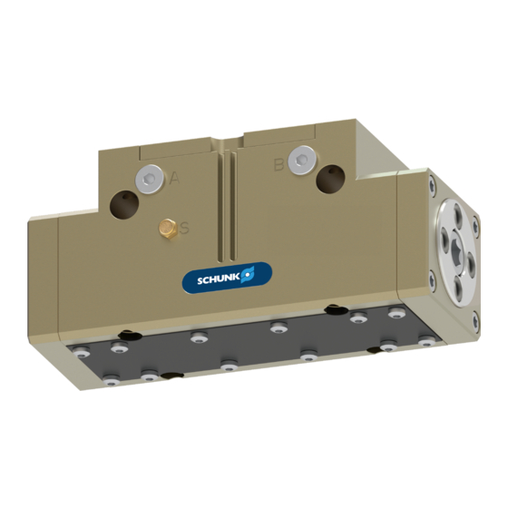
Design and description 4 Design and description 4.1 Design Sealed 2-Finger Parallel Gripper Air purge connection Base jaw Compressed air main connection Groove for magnetic switch Housing 4.2 Description Sealed 2-finger parallel gripper with large gripping force and high maximum moments due to multi-tooth guidance. 28.00 | DPG-plus | Assembly and Operating Manual | en | 389031... -
Page 24: Assembly
Assembly 5 Assembly 5.1 Installing and connecting DANGER Danger of explosion in potentially explosive areas! Observe supplementary sheet for products with explosion- • resistant versions "DPG-plus -...-EX". WARNING Risk of injury due to unexpected movements! If the power supply is switched on or residual energy remains in the system, components can move unexpectedly and cause serious injuries. -
Page 25: Mechanical Connection
Assembly Screw the product to the machine/system, Ø Mechanical connection 26]. If necessary, use appropriate connection elements (adapter ✓ plates). Observe the maximal tightening torque, admissible screw-in ✓ depth and, if necessary, strength class. Secure the gripper fingers to the base jaws, Ø... - Page 26 Assembly 5.2 Connections 5.2.1 Mechanical connection The values apply to the whole mounting surface to which the Evenness of the product is mounted. mounting surface Requirements for evenness of the mounting surface (Dimensions in mm) Edge length Permissible unevenness < 100 <...
- Page 27 Assembly The product can be mounted from three sides. Connections at the housing Connections at the housing DPG-plus Item Mounting Side A Mounting screw Max. depth of engagement from locating surface [mm] Centering sleeve Ø 5 Ø 6 Ø 8 Ø...
-
Page 28: Pneumatic Connection
Assembly DPG-plus Item Mounting Side A Mounting screw Max. depth of 25.5 engagement from locating surface [mm] Centering sleeve Ø 12 Ø 14 Ø 16 Ø 22 Ø 28 Side B Bore for mounting screws Centering sleeve Ø 12 Ø 14 Ø... - Page 29 Assembly Compressed air connection Main connections (Hose connection) (A = open, B = close) Hose-free direct connection at the base (a = open, b = close) Hose-free direct connection Air purge connection Hose-free direct connection Product O-ring Attachment Thread diameter of the air connections DPG-plus Item Connection Main connections (Hose...
-
Page 30: Installing The Ventilation Connection/Air Purge Connection
Assembly Thread diameter of the air connections DPG-plus Item Connection Main connections (Hose G 1/8 G 1/8 G 1/8 G 1/8 G 1/4 connection) Hose-free direct connection at the base Hose-free direct connection at the side Air purge connection G 1/8 G 1/8 G 1/8 5.3 Installing the ventilation connection/air purge connection... - Page 31 Assembly Installing the ventilation line or air purge connection Installing the ventilation connection The ventilation line is designed to compensate for changes in volume inside the gripper due to gripper movement. It ensures no vacuums are created inside the gripper and that no dirt is thus sucked into the gripper.
- Page 32 Assembly Actuation with air NOTE purge The use of air purge changes the gripping forces. Air purge pressure reduces the gripping force on closing and increases it on opening. Air purge actuation plan Changes in gripping force due to sealing air DGP-plus Sealing air pressure...
-
Page 33: Installing The Sensors
– The assembly and operating manual and catalog datasheet are included in the scope of delivery for the sensors and are available at schunk.com. • Information on handling sensors is available at schunk.com or from SCHUNK contact persons. 5.4.1 Overview of sensors... -
Page 34: Setting Dimensions For Magnetic Switches
Assembly 5.4.2 Setting dimensions for magnetic switches * Setting dimension I1, from product bottom edge (1) to front sensor (2) The setting dimension applies to the following sensors: • Programmable magnetic switch MMS 22-PI1, not for sizes 50, 200, 240, 300 and 380 •... -
Page 35: Switch-Off Hysteresis For Magnetic Switches
The magnetic switch MMS 22-PI1 can be adjusted and taught in two ways. • "Standard mode" allows for quick installation on the T-nut preset by SCHUNK in the groove or the defined setting dimension "l1." • In "Optimal Mode", the sensor identifies the optimal position in the groove itself. - Page 36 Assembly 5.4.4 Mounting magnetic switch MMS 22 CAUTION Risk of damage to the sensor during assembly! Observe the maximal tightening torque. • Positioning the magnetic switches Position "Gripper open" or "Part gripped (I.D. gripping)" Bring product in the position to be set. Ø...
- Page 37 The magnetic switch MMS 22-PI1 can be adjusted and taught in two ways. • "Standard mode" allows for quick installation on the T-nut preset by SCHUNK in the groove or the defined setting dimension "l1." • In "Optimal Mode", the sensor identifies the optimal position in the groove itself.
-
Page 38: Mounting Programmable Magnetic Switch Mms 22-Pi2
Assembly Setting the sensor in "Standard mode" Alternatively for size: 40 - 160, except 50 Turn the sensor 1 (1) into the groove (2). Ø OR: Slide the sensor 1 (1) into the groove (2) until the sensor 1 (1) stops at the T-nut (3). Secure the sensor 1 (1) using the set-screw (4). -
Page 39: Mounting Programmable Magnetic Switch Mms-P 22
Assembly 5.4.7 Mounting programmable magnetic switch MMS-P 22 CAUTION Risk of damage to the sensor during assembly! Observe the maximal tightening torque. • NOTE If there is no T-nut available, slide the sensor according to dimension I1 into the groove (2), Setting dimensions for magnetic switches 34]. -
Page 40: Mounting Reed Switch Rms 22
Assembly 5.4.8 Mounting reed switch RMS 22 CAUTION Risk of damage to the sensor during assembly! Observe the maximal tightening torque. • Position "Gripper open" or "Part gripped (I.D. gripping)" Bring product in the position to be set. Ø If necessary remove T-nut (3). Ø... -
Page 41: Mounting Force-Measuring Jaw Fms
Operating Instructions. NOTE Intermediate jaws (ZBA) and force-measuring jaws (FMS) are available from SCHUNK as accessories. When ordering, make sure that a size offset is formed between the intermediate and force- measuring jaws, so that the force-measuring jaws are always one size smaller than the gripper. -
Page 42: Troubleshooting
Unused air connections open. Close unused air connections. Flow control valve closed. Open the flow control valve. Component part defective. Replace component or send it to SCHUNK for repair. 28.00 | DPG-plus | Assembly and Operating Manual | en | 389031... -
Page 43: The Product Is Not Executing The Complete Stroke
Check the evenness of the mounting surface. Mechanical connection 26] Component part defective. Replace component or send it to SCHUNK for repair. Air purge set too high (> 0.5 bar). Reduce air purge (max. 0.5 bar). 6.3 Product is opening or closing abruptly... -
Page 44: Product Does Not Achieve The Opening And Closing Times
If, despite optimum air connections, the opening and closing times specified in the catalogue are not achieved, SCHUNK recommends the use of quick-air-vent- valves directly at the product. 28.00 | DPG-plus | Assembly and Operating Manual | en | 389031... -
Page 45: Maintenance
The base jaws and the guidance in the housing are matched. To exchange these parts, send the product with a repair order to SCHUNK or order the housing with the base jaws as a set. Maintenance of version with gripping force maintenance I.D. -
Page 46: Maintenance Intervals
Remove all lubrication nipples after greasing and seal! • NOTE Do not grease flat gasket (39) and flat gasket (20), Assembly drawing (previous version) 65]. SCHUNK recommends the lubricants listed. Interface Lubricant Metallic sliding surfaces Molykote BR 2 plus All seals... - Page 47 Maintenance 7.4 Threadlocker Position of the item numbers, Assembly drawing (previous version) 65] • Secure the screws and nuts listed in the table with the specified adhesive and tighten with the tightening torque, Tightening torque for screws 62]. Adhesive Item Weicon 302-41 (41) (42) (46) Weicon 302-43...
-
Page 48: Disassembly And Assembly
Maintenance 7.6 Disassembly and assembly 7.6.1 Version without gripping force maintenance Position of the item numbers: • Previous version: Assembly drawing (previous version) 65] • Successor version: Assembly drawing (successor version) 68] Disassembling Remove the compressed air hose. Ø Unfasten and remove the screws (47). Ø... - Page 49 Maintenance Assembling NOTE Tighten all screws with the required tightening torque., Tightening torque for screws 62]. Insert the base jaw (2/7) into the intermediate jaw (13) and Ø tighten the screw (43). Insert the seal (31) into the housing (1) from above. Ø Push the base jaw (2/7) into the housing (1), observing the Ø...
- Page 50 Maintenance Do not screw the screw (42) completely into the cover (12). The Ø gap between the side cover (12) and the housing (1) should be approximately divided in half. Allow the product to run approx. 20 cycles in order to center Ø...
-
Page 51: Variant With Maintenance Of Gripping Force (Od Gripping)
Maintenance 7.6.2 Variant with maintenance of gripping force (OD gripping) Position of the item numbers: • Previous version: Assembly drawing (previous version) 65] • Successor version: Assembly drawing (successor version) 68] WARNING Risk of injury due to spring forces! The cover is under spring tension. Carefully disassemble the product. - Page 52 Maintenance Size 125 or above: Remove the spacer bolt (11) from the Ø housing (1). Push the pistons (3/8) upwards out of the housing (1). Ø NOTE Do not disassemble the intermediate jaw (13) from the base jaw (2/7). Pull the base jaws (2/7) out of the housing (1). Ø...
- Page 53 Maintenance • Dimensions of assembly device, Sizes 40 - 100 63]. Mounting cylinder piston for size 40 - 100 Grease and install device (100). Ø Push the cylinder piston (60/72) with seal (30) and the Ø compression spring (25) into the housing (1) from below, observing the correct installation position. Ensure that the sealing lips of the seal (30) do not become damaged while pushing in the cylinder piston (60/72).
- Page 54 Maintenance • Dimensions of assembly device, Sizes 125 - 380 64]. Mounting cylinder piston for size 125 - 380 Slide the compression springs (25), spacer bolts (11) and Ø cylinder pistons (60/72) with the seals (30/33) from below into the housing (1), ensuring the correct installation position. Ensure that the sealing lips of the seal (30) do not become damaged while pushing in the cylinder piston (60/72).
- Page 55 Maintenance Insert seals (34) / (32/38) into the cover (9). Final assembly Ø Insert the centering sleeves (19) into the housing (1) and fasten Ø the cover (9) to the housing (1) with screws (46). Previous version: Insert the gasket (14) into the housing (1). Ø Note: The product must be in the "Gripper closed" position, to prevent the gasket (14) from jamming.
-
Page 56: Version With Gripping Force Maintenance I.d
Maintenance 7.6.3 Version with gripping force maintenance I.D. Position of the item numbers: • Previous version: Assembly drawing (previous version) 65] • Successor version: Assembly drawing (successor version) 68] WARNING Risk of injury due to spring forces! The cover is under spring tension. Carefully disassemble the product. - Page 57 Maintenance Previous version: Mark the installation position between the Ø cylinder piston (60) and the housing (1). Successor version: Mark the installation position between the cylinder piston (71) and the housing (1). Unscrew and remove the screw (40). Ø Previous version: Remove the cylinder piston (60) from the Ø...
- Page 58 Maintenance Insert the centering sleeves (19) into the housing (1). Ø Clamp the product in a vise so that the screws (46) can be Ø assembled. Fasten the cover (9) with the screws (46). Ø Previous version: Insert the gasket (14) into the housing (1). Ø...
-
Page 59: Version With "Force Amplification Cylinder" (Kvz)
Maintenance 7.6.4 Version with "force amplification cylinder" (KVZ) Position of the item numbers: • Previous version: Assembly drawing (previous version) 65] • Successor version: Assembly drawing (successor version) 68] Dismantling Remove the compressed air hose. Ø Unfasten and remove the screws (47). Ø... - Page 60 Maintenance Assembly Insert the base jaw (2/7) into the intermediate jaw (13) and Ø tighten the screw (43). Push the base jaw (2/7) into the housing (1), observing the Ø correct installation position. Position the base jaws (2/7) so that the piston (3/8) can be Ø...
- Page 61 Maintenance Do not screw the screw (42) completely into the cover (12). The Ø gap between the side cover (12) and the housing (1) should be approximately divided in half. Allow the product to run approx. 20 cycles in order to center Ø...
-
Page 62: Position Of The Plast-O-Seal (Previous Version)
Maintenance 7.6.5 Position of the Plast-o-Seal (previous version) Position of the item numbers, Assembly drawing (previous version) 65] Plast-o-Seal Position of the Plast-o-Seal 7.6.6 Tightening torque for screws Position of the item numbers, Assembly drawing (previous version) 65] Max. tightening torque [Nm] Size Item 0.75... -
Page 63: Assembly Device Cylinder Piston With Gripping Force Maintenance
Maintenance 7.7 Assembly device cylinder piston with gripping force maintenance 7.7.1 Sizes 40 - 100 D H8 B - B 0.02 0.02 l 1 ± 0.02 Ø 15 A - A Cylinder piston assembly device - dimensions in mm DPG-plus 40 20 22.5 14.5 DPG-plus 50 DPG-plus 64 DPG-plus 80... -
Page 64: Sizes 125 - 380
Maintenance 7.7.2 Sizes 125 - 380 Cylinder piston assembly device - dimensions in mm DPG-plus 125 DPG-plus 160 90.5 57.5 DPG-plus 200 DPG-plus 240 13.5 DPG-plus 300 114.3 17.5 DPG-plus 380 13.5 DPG-plus 125 DPG-plus 160 58.5 74.5 DPG-plus 200 DPG-plus 240 DPG-plus 300 M10 115.3... -
Page 65: Assembly Drawing (Previous Version)
Maintenance 7.8 Assembly drawing (previous version) The following figures are example images. They serve for illustration and assignment of the spare parts. Variations are possible depending on size and variant. Wearing part, replace during maintenance. Included in the seal kit. Seal kit can only be ordered completely. -
Page 66: Assembly Of Variants Od / Id / Without Maintenance Of Gripping Force
Maintenance 7.8.1 Assembly of variants OD / ID / without maintenance of gripping force Assembly of the variants O.D. gripping/I.D. gripping/without maintenance of gripping force (previous version) 28.00 | DPG-plus | Assembly and Operating Manual | en | 389031... -
Page 67: Assembly Of The Variant With Force Amplification Cylinder
Maintenance 7.8.2 Assembly of the variant with force amplification cylinder Assembly of the variant with force amplification cylinder (previous version) Gripper variants with force amplification cylinders are not permitted for use in explosion-protected applications (EX). 28.00 | DPG-plus | Assembly and Operating Manual | en | 389031... -
Page 68: Assembly Drawing (Successor Version)
Maintenance 7.9 Assembly drawing (successor version) The following figures are example images. They serve for illustration and assignment of the spare parts. Variations are possible depending on size and variant. Wearing part, replace during maintenance. Contained in the spare part kit "seal kit". The spare part kit can be ordered completely only. -
Page 69: Assembly Of Variants Od / Id / Without Maintenance Of Gripping Force
Maintenance 7.9.1 Assembly of variants OD / ID / without maintenance of gripping force Assembly of the variants O.D. gripping/I.D. gripping/without maintenance of gripping force (successor version) 28.00 | DPG-plus | Assembly and Operating Manual | en | 389031... -
Page 70: Assembly Of The Variant With Force Amplification Cylinder
Maintenance 7.9.2 Assembly of the variant with force amplification cylinder Assembly of the variant with force amplification cylinder (successor version) Gripper variants with force amplification cylinders are not permitted for use in explosion-protected applications (EX). 28.00 | DPG-plus | Assembly and Operating Manual | en | 389031... -
Page 71: Appendix
Appendix 8 Appendix 8.1 Differentiation between the previous version and the successor version The product has been redesigned as of 2018. The modified successor version is directly interchangeable with the previous version and replaces it. The difference between the two versions lies exclusively in the design and is therefore only relevant for spare parts such as the sealing kit. - Page 72 Appendix DPG-plus Ident number Ident number Previous version Successor version 50-2-IS-EX 304215 1315204 50-2-IS-V 1321195 50-2-KVZ 304308 1315957 50-2-V 1321190 64-1 304311 1315967 64-1-AS 304313 1315971 64-1-AS-EX 304222 1315214 64-1-AS-KVZ 304319 1315972 64-1-AS-V 39304313 1321199 64-1-EX 304220 1315207 64-1-IS 304315 1315974 64-1-IS-EX 304224...
- Page 73 Appendix DPG-plus Ident number Ident number Previous version Successor version 80-1-V 39304321 1321206 80-2 304322 1315981 80-2-AS 304324 1315986 80-2-AS-EX 304233 1315245 80-2-AS-V 1321211 80-2-EX 304231 1315241 80-2-IS 304326 1315992 80-2-IS-EX 304235 1315248 80-2-IS-V 1321213 80-2-KVZ 304328 1315982 80-2-V 39304322 1321207 100-1 304331...
- Page 74 Appendix DPG-plus Ident number Ident number Previous version Successor version 125-1-AS- 304349 1316067 125-1-AS-V 39304343 1321228 125-1-EX 304250 1315263 125-1-IS 304345 1316069 125-1-IS-EX 304254 1315270 125-1-IS- 304340 1316070 125-1-IS-V 39304345 1321230 125-1-KVZ 304347 1316059 125-1-V 39304341 1321224 125-2 304342 1316061 125-2-AS 304344 1316068...
- Page 75 Appendix DPG-plus Ident number Ident number Previous version Successor version 160-2-AS-V 39304354 1321238 160-2-EX 304261 1315275 160-2-IS 304356 1316086 160-2-IS-EX 304265 1315282 160-2-IS-V 1321241 160-2-KVZ 304358 1316080 160-2-V 39304352 1321235 200-1 304361 1316090 200-1-AS 304363 1316092 200-1-AS-EX 304272 1315289 200-1-AS-V 39304363 1321244 200-1-EX...
- Page 76 Appendix DPG-plus Ident number Ident number Previous version Successor version 240-2-AS-V 1321252 240-2-EX 304281 1315296 240-2-IS 304376 1316104 240-2-IS-EX 304285 1315305 240-2-IS-V 1321254 240-2-V 1321249 300-1 304381 1316107 300-1-AS 304383 1316109 300-1-AS-EX 304512 1315311 300-1-AS-V 39304383 1321258 300-1-EX 304510 1315309 300-1-IS 304385 1316111...
-
Page 77: Translation Of Original Declaration Of Incorporation
9 Translation of original declaration of incorporation in terms of the Directive 2006/42/EG, Annex II, Part 1.B of the European Parliament and of the Council on machinery. Manufacturer/ SCHUNK GmbH & Co. KG Clamping and gripping technology Distributor Bahnhofstr. 106 - 134 D-74348 Lauffen/Neckar... -
Page 78: Annex To Declaration Of Incorporation
Translation of original declaration of incorporation 9.1 Annex to Declaration of Incorporation according 2006/42/EG, Annex II, No. 1 B 1.Description of the essential health and safety requirements pursuant to 2006/42/EC, Annex I that are applicable and that have been fulfilled with: Product designation Sealed 2-Finger Parallel Gripper Type designation DPG-plus... - Page 79 Translation of original declaration of incorporation Protection against mechanical hazards 1.3.1 Risk of loss of stability 1.3.2 Risk of break-up during operation 1.3.3 Risks due to falling or ejected objects 1.3.4 Risks due to surfaces, edges or angles 1.3.5 Risks related to combined machinery 1.3.6 Risks related to variations in operating conditions 1.3.7...
- Page 80 Translation of original declaration of incorporation Maintenance 1.6.1 Machinery maintenance 1.6.2 Access to operating positions and servicing points 1.6.3 Isolation of energy sources 1.6.4 Operator intervention 1.6.5 Cleaning of internal parts Information 1.7.1 Information and warnings on the machinery 1.7.1.1 Information and information devices 1.7.1.2 Warning devices...
Need help?
Do you have a question about the DPG-plus Series and is the answer not in the manual?
Questions and answers