
Related Manuals for SCHUNK PGL-plus-P


Summary of Contents for SCHUNK PGL-plus-P
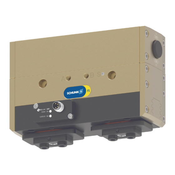
- Page 1 Translation of the original manual Assembly- and Operating Manual PGL-plus-P 2-Finger Parallel Gripper...
- Page 2 Imprint Imprint Copyright: This manual is protected by copyright. The author is SCHUNK GmbH & Co. KG. All rights reserved. Technical changes: We reserve the right to make alterations for the purpose of technical improvement. Document number: 1508050 Version: 02.00 | 26/10/2022 | en...
-
Page 3: Table Of Contents
Design ......................... 18 4.1.1 Variant IOL structure ................ 19 Description ...................... 20 Assembly and settings .................... 21 Safety........................ 21 Installing and connecting.................. 22 Connections...................... 23 5.3.1 Mechanical connection................ 23 5.3.2 Pneumatic connection................ 25 02.00 | PGL-plus-P | Assembly- and Operating Manual | en | 1508050... - Page 4 Translation of original declaration of incorporation .......... 61 10 UKCA declaration of incorporation................ 62 11 Annex to Declaration of Incorporation .............. 63 12 EU-Declaration of Conformity ................. 66 13 UKCA Declaration of Conformity ................ 67 02.00 | PGL-plus-P | Assembly- and Operating Manual | en | 1508050...
-
Page 5: General
Non-observance can cause minor injuries. NOTICE Material damage! Information about avoiding material damage. 1.1.2 Definition of Terms The term "product" replaces the product name on the title page in this manual. 02.00 | PGL-plus-P | Assembly- and Operating Manual | en | 1508050... -
Page 6: Symbol Definition
• PGL-plus-P with integrated sensor system (IOL) NOTE Variants with safe, certified gripping force maintenance (ASC and ISC) are described in a separate manual. This can be downloaded from schunk.com. 02.00 | PGL-plus-P | Assembly- and Operating Manual | en | 1508050... -
Page 7: Warranty
1505890 PGL-plus-P 10-V 1510679 PGL-plus-P 13 1505891 PGL-plus-P 13-V 1510690 PGL-plus-P 16 1505892 PGL-plus-P 16-V 1510691 PGL-plus-P 20 1505894 PGL-plus-P 20-V 1510692 PGL-plus-P 25 1505895 PGL-plus-P 25-V 1510693 02.00 | PGL-plus-P | Assembly- and Operating Manual | en | 1508050... -
Page 8: Accessories
Contents of the spare parts package, 57]. ID. No. spare part kit "IO-Link sensor" Size ID number PGL-plus-P 10 1524550 PGL-plus-P 13 1524554 PGL-plus-P 16 1524561 PGL-plus-P 20 1524563 PGL-plus-P 25 1524564 02.00 | PGL-plus-P | Assembly- and Operating Manual | en | 1508050... -
Page 9: Basic Safety Notes
Use of unauthorized spare parts Using unauthorized spare parts can endanger personnel and damage the product or cause it to malfunction. • Use only original spare parts or spares authorized by SCHUNK. 02.00 | PGL-plus-P | Assembly- and Operating Manual | en | 1508050... -
Page 10: Gripper Fingers
• Make sure that the product is used only in the context of its } 3 [ / defined application parameters, 16]. 02.00 | PGL-plus-P | Assembly- and Operating Manual | en | 1508050... -
Page 11: Personnel Qualification
Due to its technical training, knowledge and experience, service the manufacturer personnel of the manufacturer is able to perform the delegated tasks and to recognize and avoid possible dangers. 02.00 | PGL-plus-P | Assembly- and Operating Manual | en | 1508050... -
Page 12: Personal Protective Equipment
• Eliminate any malfunction immediately. • Observe the care and maintenance instructions. • Observe the current safety, accident prevention and environmental protection regulations regarding the product's application field. 02.00 | PGL-plus-P | Assembly- and Operating Manual | en | 1508050... -
Page 13: Transport
• If the energy supply is connected, do not move any parts by hand. • Do not reach into the open mechanism or movement area of the product during operation. 02.00 | PGL-plus-P | Assembly- and Operating Manual | en | 1508050... -
Page 14: Protection During Handling And Assembly
The protective cover and protective fence must be rigid enough to withstand the maximum possible movement energy. EMERGENCY STOP switches must be easily 02.00 | PGL-plus-P | Assembly- and Operating Manual | en | 1508050... -
Page 15: Notes On Particular Risks
For all work in the vicinity of hot surfaces, wear safety gloves. • Before carrying out any work, make sure that all surfaces have • cooled down to the ambient temperature. 02.00 | PGL-plus-P | Assembly- and Operating Manual | en | 1508050... -
Page 16: Technical Data
Avoid heating the product up to the specified maximum ambient temperature by taking appropriate protective measures, otherwise this can lead to increased wear and reduce the service life. Contact SCHUNK about selecting possible protective measures. 02.00 | PGL-plus-P | Assembly- and Operating Manual | en | 1508050... - Page 17 (23°C), gripping height at point "P" (see catalog) and when operating without air purge. Deviations may occur with other parameters. More technical data is included in the catalog data sheet. Whichever is the latest version. 02.00 | PGL-plus-P | Assembly- and Operating Manual | en | 1508050...
-
Page 18: Design And Description
Design and description 4 Design and description 4.1 Design 2-Finger Parallel Gripper Housing Base jaw Compressed air main connection Air purge connection Groove for magnetic switch 02.00 | PGL-plus-P | Assembly- and Operating Manual | en | 1508050... -
Page 19: Variant Iol Structure
On (Orange) Sensor output S1=1 On (Green) Sensor is ready for IO-Link operation. communication not active. Sensor output S1=0 Flashing (Green), IO-Link 100 ms off, 90 ms on communication active. 02.00 | PGL-plus-P | Assembly- and Operating Manual | en | 1508050... -
Page 20: Description
Integrated Sensor System, IO-Link Protocol". 4.2 Description Universal 2-finger parallel gripper with a large jaw stroke, integrated sensor system and high maximum moments due to use of a multi-tooth guidance. 02.00 | PGL-plus-P | Assembly- and Operating Manual | en | 1508050... -
Page 21: Assembly And Settings
especially in awkward postures – can lead to back disorders and injuries. Use appropriate aids to lift and handle the product. • Take safety measures that prevent the product from falling. • Wear suitable protective equipment. • 02.00 | PGL-plus-P | Assembly- and Operating Manual | en | 1508050... -
Page 22: Installing And Connecting
10. Variant IOL: Place cable for IO-Link on the M8 connector and } 4.1.1 [ / tighten the threaded ring by hand 19]. For more information on commissioning, see Software Manual "PGL-plus-P with Integrated Sensor System, IO-Link Protocol". 02.00 | PGL-plus-P | Assembly- and Operating Manual | en | 1508050... -
Page 23: Connections
Ø 6 Ø 8 Ø 10 Ø 10 Ø 14 Mounting screw Mounting screw strength 12.9 class t1: Screw-in depth from stop face [mm] t2: Thread depth [mm] 02.00 | PGL-plus-P | Assembly- and Operating Manual | en | 1508050... - Page 24 Ø 10 Ø 12 Side B Mounting screw Mounting screw according DIN EN ISO 4762 to standard Centering sleeve Ø 6 Ø 6 Ø 8 Ø 10 Ø 12 02.00 | PGL-plus-P | Assembly- and Operating Manual | en | 1508050...
-
Page 25: Pneumatic Connection
Product variants are also offered with mechanical gripping force via springs, which also ensure a minimum clamping force in the event of a pressure drop. 02.00 | PGL-plus-P | Assembly- and Operating Manual | en | 1508050... - Page 26 [mm] Air purge connection The air purge makes it difficult for dirt to penetrate the product. The product achieves protection class IP 67 through use of an air purge. 02.00 | PGL-plus-P | Assembly- and Operating Manual | en | 1508050...
-
Page 27: Electrical Connection - Iol Variant
Signal Description +24 V Switching signal DI (SIO) Switching signal DI (SIO) or IO-Link (SDCI) NOTE For more information, see Software Manual "PGL-plus-P with Integrated Sensor System, IO-Link Protocol". 02.00 | PGL-plus-P | Assembly- and Operating Manual | en | 1508050... -
Page 28: Attaching Additional Structure
• When inductive proximity switches are used, the connections for the additional structure cannot be fully utilized, since the control cams attached to the base jaws overrun the threads and a collision would otherwise occur. 02.00 | PGL-plus-P | Assembly- and Operating Manual | en | 1508050... - Page 29 • Mount the additional structure on the product using four screws and centering sleeves. Note: The centering sleeves are not included in the scope of ✓ delivery and can be ordered from SCHUNK. 02.00 | PGL-plus-P | Assembly- and Operating Manual | en | 1508050...
-
Page 30: Mounting The Sensor
• The positions "Gripper closed" and "Gripper open" are set in the factory. • For more information on commissioning, see Software Manual "PGL-plus-P with Integrated Sensor System, IO-Link Protocol". 02.00 | PGL-plus-P | Assembly- and Operating Manual | en | 1508050... -
Page 31: Setting Dimensions For Magnetic Switches
PGL-plus-P 16–25: Setting dimension l1, cable outlet left Setting dimension l1 - cable outlet left Size Setting dimensions l1 [mm] MMS 22-PI1 MMS 22-A MMS 22-IOL MMS 22-PI2 17.8 19.8 18.6 18.4 20.4 19.8 33.8 45.2 47.2 45.6 62.6 64.1 63.7 02.00 | PGL-plus-P | Assembly- and Operating Manual | en | 1508050... - Page 32 PGL-plus-P 16–25: Setting dimension I1, cable outlet right Setting dimension I1 - cable outlet right Size Setting dimensions l1 [mm] MMS 22-PI1 MMS 22-A MMS 22-IOL MMS 22-PI2 46.7 44.9 47.3 45.4 47.2 61.9 61.2 72.1 72.9 91.5 89.9 91.1 02.00 | PGL-plus-P | Assembly- and Operating Manual | en | 1508050...
-
Page 33: Switch-Off Hysteresis For Magnetic Switches
20% of the nominal stroke per jaw X > 10 mm 10% of the nominal stroke per jaw Example: Product with 7 mm nominal stroke per jaw 7 mm * 20% = 1.4 mm 02.00 | PGL-plus-P | Assembly- and Operating Manual | en | 1508050... -
Page 34: Mounting Inductive Proximity Switch In
3. Secure the control cam (4) with screws (5). 4. Loosen screw (8) and push sensor holder (6) into the side of the sensor rail (2). Observe the installation position, the long side must point downwards. 02.00 | PGL-plus-P | Assembly- and Operating Manual | en | 1508050... - Page 35 Secure the bracket (6) in this position with screw (8). Tightening torque: 0.2 Nm ✓ 6. Bring the product into position "Gripper closed" or "Part gripped (O.D. gripping)" and test the function. 02.00 | PGL-plus-P | Assembly- and Operating Manual | en | 1508050...
-
Page 36: Mounting Mms 22 Magnetic Switch
4. Pull sensor 2 (1) back again slowly until it switches. 5. Secure sensor 2 (1) using the set-screw (4). Tightening torque: 10 Ncm 6. Bring the product into position "Gripper closed" or "Part gripped (O.D. gripping)" and test the function. 02.00 | PGL-plus-P | Assembly- and Operating Manual | en | 1508050... -
Page 37: Mounting Programmable Mms 22-Pi2 Magnetic Switch
OR: Slide the sensor (1) into the groove (2) until the sensor (1) stops at the T-nut (3). 2. Secure the sensor (1) using the set-screw (4). Tightening torque: 10 Ncm 3. Adjust sensor (1), see sensor assembly and operating manual. 02.00 | PGL-plus-P | Assembly- and Operating Manual | en | 1508050... -
Page 38: Mounting Mms 22-Pi1 Programmable Magnetic Switch
OR: Slide sensor 1 (1) into the groove (2) until sensor 1 (1) stops at starting point/groove end "B". 4. Hold teaching tool to the sensor 1 (1) until the sensor flashes. 5. Pull sensor 1 (1) back again slowly until it switches. 02.00 | PGL-plus-P | Assembly- and Operating Manual | en | 1508050... - Page 39 2. Secure the sensor 1 (1) using the set-screw (4). Tightening torque: 10 Ncm 3. Adjust sensor 1 (1), see sensor assembly and operating manual. 4. Repeat steps for sensor 2. 02.00 | PGL-plus-P | Assembly- and Operating Manual | en | 1508050...
-
Page 40: Mounting The Magnetic Switch Mms 22-Iol
2. Slide sensor (1) into the groove (2) until the sensor (1) stops at the T-nut (3). 3. Secure the sensor (1) using the set-screw (4). Tightening torque: 10 Ncm 4. Adjust sensor (1), see the Sensor Assembly and Operating Manual. 02.00 | PGL-plus-P | Assembly- and Operating Manual | en | 1508050... -
Page 41: Mounting Analog Mms 22-A Magnetic Switch
• The function of the sensor in the two peripheral areas is not ensured if the lower groove is used or the sensor is inserted offset by 180°. 02.00 | PGL-plus-P | Assembly- and Operating Manual | en | 1508050... -
Page 42: Troubleshooting
Mounting surface is not sufficiently flat. Check the evenness of the mounting surface. } 5.3.1 [ / 23] Loading too large. Check permissible weight and length of the gripper fingers. 02.00 | PGL-plus-P | Assembly- and Operating Manual | en | 1508050... -
Page 43: Product Does Not Achieve The Opening And Closing Times
Clean and lubricate product. movement space. Pressure drops below minimum. Check air supply. } 3 [ / 16] Component part defective. Replace component or send it to SCHUNK for repair. 02.00 | PGL-plus-P | Assembly- and Operating Manual | en | 1508050... -
Page 44: Variant Iol
Corrective action No voltage supply Check device status via IO-Link. Take measures according to error message. Acknowledge error. See Software Manual "PGL-plus-P with Integrated Sensor System, IO-Link Protocol". 02.00 | PGL-plus-P | Assembly- and Operating Manual | en | 1508050... -
Page 45: Maintenance
A sharp burr can form on the gripper fingers due to wear, which can lead to cuts. Wear suitable protective equipment. • Original spare parts Use only original spare parts of SCHUNK when replacing spare and wear parts. 02.00 | PGL-plus-P | Assembly- and Operating Manual | en | 1508050... -
Page 46: Maintenance Intervals
Perform all maintenance work without a gripped workpiece! NOTICE Material damage due to hardening lubricants! Lubricants harden more quickly at temperatures above 60°C, leading to possible product damage. Reduce the lubricant intervals accordingly. • 02.00 | PGL-plus-P | Assembly- and Operating Manual | en | 1508050... -
Page 47: Lubricants/Lubrication Points (Basic Lubrication)
* The product contains food-compliant lubricants as standard. The requirements of standard EN 1672-2:2020 are not fully met. NOTE • Change contaminated food-compliant lubricant. • Observe information in the safety data sheet from the lubricant manufacturer. 02.00 | PGL-plus-P | Assembly- and Operating Manual | en | 1508050... -
Page 48: Replace Seals
6. Mark the installation position of the jaws (2) on the guide housing (1). 7. Remove screws (13) and take out base jaws (4). 8. Remove screws (116) and take off the cover (11). 02.00 | PGL-plus-P | Assembly- and Operating Manual | en | 1508050... - Page 49 18. Insert the flat gasket (17) into the cover (9). 19. Secure the cover (9) with the screws (120). 20. Mount product onto the system/machine. 21. Connect all compressed air lines. 02.00 | PGL-plus-P | Assembly- and Operating Manual | en | 1508050...
-
Page 50: Changing Seals (Variant With "O.d. Gripping" Gripping Force Maintenance)
Gear rack removal direction (5) Remove old seals There is no compressed air or energy supply. ■ No workpiece is gripped. ■ 1. Remove all compressed air lines, } 5.3.2 [ / 25]. 02.00 | PGL-plus-P | Assembly- and Operating Manual | en | 1508050... - Page 51 IMPORTANT! Observe the installation position of the jaws (2) in the housing (1). 12. Insert the magnet holder (31) into the jaw (2) and fasten it with the screw (119). 13. Insert the flat gasket (16). 02.00 | PGL-plus-P | Assembly- and Operating Manual | en | 1508050...
-
Page 52: Changing Seals (Variant With "I.d. Gripping" Gripping Force Maintenance)
Carefully dismantle the product. • Changing seals (variant with gripping force maintenance "I.D. gripping" (IS)) 02.00 | PGL-plus-P | Assembly- and Operating Manual | en | 1508050... - Page 53 4. Press the gear rack (5) into the drive housing (3). IMPORTANT! Observe the installation position and direction of the gear racks (5) in the drive housing (3). 5. Press the driver (8) into the gear rack (5) and secure with the screw (118). 02.00 | PGL-plus-P | Assembly- and Operating Manual | en | 1508050...
- Page 54 Tighten the screw (131). 19. Secure the cover (25) with screws (128, 129). 20. Mount product onto the system/machine. 21. Connect all compressed air lines. 02.00 | PGL-plus-P | Assembly- and Operating Manual | en | 1508050...
-
Page 55: Changing The Sensor (For Iol Variant)
4. Install and tighten the screws (4) with medium-strength threadlocker. Tightening torque: 0.11 Nm ✓ NOTE For information on commissioning after a sensor change, see Software Manual "PGL-plus-P with Integrated Sensor System, IO- Link Protocol" 02.00 | PGL-plus-P | Assembly- and Operating Manual | en | 1508050... -
Page 56: Tightening Torques
Item Item Item Item 120, 128, PGL-plus-P 10 0.53 0.27 0.06 0.53 PGL-plus-P 13 0.94 0.53 0.11 0.94 PGL-plus-P 16 0.94 0.21 PGL-plus-P 20 0.21 PGL-plus-P 25 0.45 02.00 | PGL-plus-P | Assembly- and Operating Manual | en | 1508050... -
Page 57: Assembly Drawing
Maintenance 7.7 Assembly drawing PGL-plus-P 10 – 25 standard Not with PGL-plus-P 16 – 25 ** Included in the "sealing kit" spare parts package 02.00 | PGL-plus-P | Assembly- and Operating Manual | en | 1508050... - Page 58 Maintenance PGL-plus-P 10 – 25 with gripping force maintenance for O.D. gripping Not with PGL-plus-P 16 – 25 ** Included in the "sealing kit" spare parts package 02.00 | PGL-plus-P | Assembly- and Operating Manual | en | 1508050...
- Page 59 Maintenance PGL-plus-P 10 – 25 with gripping force maintenance for I.D. gripping Not with PGL-plus-P 16 – 25 ** Included in the "sealing kit" spare parts package 02.00 | PGL-plus-P | Assembly- and Operating Manual | en | 1508050...
-
Page 60: Disassembly And Disposal
• Remove any lubricant and dispose of in an environmentally friendly manner. • Follow local regulations on dispatching product components for recycling or proper disposal. 02.00 | PGL-plus-P | Assembly- and Operating Manual | en | 1508050... -
Page 61: Translation Of Original Declaration Of Incorporation
Person authorized to compile the technical documentation: Robert Leuthner, Address: see manufacturer's address p.p. Ralf Winkler; Head of Technology & Engineering, Lauffen/Neckar, October 2022 Mechanics Gripping Systems 02.00 | PGL-plus-P | Assembly- and Operating Manual | en | 1508050... -
Page 62: Ukca Declaration Of Incorporation
Person authorized to compile the technical documentation: Marcel Machado, address: refer to manufacturer's address p.p. Ralf Winkler; Head of Technology & Engineering, Lauffen/Neckar, October 2022 Mechanics Gripping Systems 02.00 | PGL-plus-P | Assembly- and Operating Manual | en | 1508050... -
Page 63: Annex To Declaration Of Incorporation
1.3.1 Risk of loss of stability 1.3.2 Risk of break-up during operation 1.3.3 Risks due to falling or ejected objects 1.3.4 Risks due to surfaces, edges or angles 02.00 | PGL-plus-P | Assembly- and Operating Manual | en | 1508050... - Page 64 Risk of slipping, tripping or falling 1.5.16 Lightning Maintenance 1.6.1 Machinery maintenance 1.6.2 Access to operating positions and servicing points 1.6.3 Isolation of energy sources 1.6.4 Operator intervention 1.6.5 Cleaning of internal parts 02.00 | PGL-plus-P | Assembly- and Operating Manual | en | 1508050...
- Page 65 Supplementary essential health and safety requirements for machinery intended for underground work Supplementary essential health and safety requirements for machinery presenting particular hazards due to the lifting of persons 02.00 | PGL-plus-P | Assembly- and Operating Manual | en | 1508050...
-
Page 66: Eu-Declaration Of Conformity
• REACH Regulation EC No. 1907/2006 Signed for and on behalf of: SCHUNK GmbH & Co. KG p.p. Ralf Winkler; Head of Technology & Engineering, Lauffen/Neckar, October 2022 Mechanics Gripping Systems 02.00 | PGL-plus-P | Assembly- and Operating Manual | en | 1508050... -
Page 67: Ukca Declaration Of Conformity
Person authorized to compile the technical documentation: Marcel Machado, address: refer to manufacturer's address p.p. Ralf Winkler; Head of Technology & Engineering, Lauffen/Neckar, October 2022 Mechanics Gripping Systems 02.00 | PGL-plus-P | Assembly- and Operating Manual | en | 1508050... - Page 68 Translation of the original manual SCHUNK GmbH & Co. KG Clamping and gripping technology Bahnhofstr. 106 - 134 D-74348 Lauffen/Neckar Tel. +49-7133-103-0 Fax +49-7133-103-2399 info@de.schunk.com schunk.com Folgen Sie uns I Follow us...
Need help?
Do you have a question about the PGL-plus-P and is the answer not in the manual?
Questions and answers