
Subscribe to Our Youtube Channel
Related Manuals for SCHUNK NSR-A Series


Summary of Contents for SCHUNK NSR-A Series
- Page 1 Translation of Original Operating Manual Assembly and Operating Manual NSR-A Pallet Changing System...
- Page 2 Imprint Copyright: This manual is protected by copyright. The author is SCHUNK GmbH & Co. KG. All rights reserved. Any reproduction, processing, distribution (making available to third parties), translation or other usage - even excerpts - of the manual is especially prohibited and requires our written approval.
-
Page 3: Table Of Contents
Table of Contents Table of Contents General........................ 5 About this manual .................... 5 1.1.1 Presentation of Warning Labels ............... 5 1.1.2 Applicable documents ................ 6 1.1.3 Sizes ...................... 6 Warranty ...................... 6 Scope of delivery .................... 7 1.3.1 Accessory pack for NSR-100 .............. 7 1.3.2 Accessory pack for NSR-160 .............. 7 Accessories ...................... - Page 4 Table of Contents Design and Description ................... 23 Application example for automated pallet loading .......... 24 Pallet adapter for NSR-A 100................ 25 Pallet adapter for NSR-A 160................ 28 Coupling interface for NSR-A 100 and NSR-A 160 .......... 31 Assembly ........................ 32 Assembly requirements.................. 32 Unpacking and transporting ................
-
Page 5: General
General 1 General 1.1 About this manual This manual contains important information for a safe and appropriate use of the product. This manual is an integral part of the product and must be kept accessible for the personnel at all times. Before starting work, the personnel must have read and understood this operating manual. -
Page 6: Applicable Documents
• General terms of business * • Catalog data sheet of the purchased product * The documents marked with an asterisk (*) can be downloaded on our homepage schunk.com 1.1.3 Sizes This operating manual applies to the following sizes: • NSR-A 100 •... -
Page 7: Scope Of Delivery
General 1.3 Scope of delivery The scope of delivery includes • Pallet changing system in the ordered size (NSR-A 100 or NSR-A 160) • Assembly and Operating Manual • Accessory pack 1.3.1 Accessory pack for NSR-100 Content of the accessory pack: •... -
Page 8: Accessories
General 1.4 Accessories (see catalog or data sheets when ordering separately) • Pallet adapter for NSR-A 100: – PKL 100, Adapter 90° with mounting stud – PKL 100, straight Adapter 0° with mounting stud for NSR-A 160: – PKL 160, Adapter 90° with mounting stud –... -
Page 9: Basic Safety Notes
Use of unauthorized spare parts Using unauthorized spare parts can endanger personnel and damage the product or cause it to malfunction. • Use only original spare parts or spares authorized by SCHUNK. 06.00 | NSR-A | Assembly and Operating Manual | en | 389722... -
Page 10: Environmental And Operating Conditions
Basic safety notes 2.5 Environmental and operating conditions Required ambient conditions and operating conditions Incorrect ambient and operating conditions can make the product unsafe, leading to the risk of serious injuries, considerable material damage and/or a significant reduction to the product's life span. •... -
Page 11: Personal Protective Equipment
Only allow specialists to remedy malfunctions. Spare parts Only use original SCHUNK spare parts. Environmental regulations The applicable environmental regulations must be observed for all maintenance and repair work. -
Page 12: Notes On Safe Operation
If the pallet changing system is to be operated in an environment with abrasive dusts or corrosive or aggressive fumes or fluids, prior approval must be obtained from SCHUNK. 06.00 | NSR-A | Assembly and Operating Manual | en | 389722... -
Page 13: Handling
12.9 may be used for the screw connection. Only original SCHUNK clamping pins may be used. If the clamping pin is to be used in customer-specific devices, a sufficiently dimensioned pallet adapter or a sufficiently thick mounting material is provided. -
Page 14: Disposal
Basic safety notes 2.12 Disposal Handling of disposal The incorrect handling of disposal may impair the product's safety and cause serious injuries as well as considerable material and environmental harm. • Follow local regulations on dispatching product components for recycling or proper disposal. 2.13 Fundamental dangers General •... -
Page 15: Protection During Commissioning And Operation
Basic safety notes 2.13.2 Protection during commissioning and operation Falling or violently ejected components Falling and violently ejected components can cause serious injuries and even death. • Take appropriate protective measures to secure the danger zone. • Never step into the danger zone during operation. 2.13.3 Protection against dangerous movements Unexpected movements Residual energy in the system may cause serious injuries while... -
Page 16: Notes On Particular Risks
Basic safety notes 2.14 Notes on particular risks WARNING Risk of injury due to falling heavy components! If the clamping pin is loosened erroneously or as a result of negligence, the device, pallet or workpiece may fall down and cause severe injuries. During operation, loosening the clamping pin as a result of •... - Page 17 Basic safety notes CAUTION Risk of injury due to compressed air hoses coming loose when connected improperly! Use check valves or safety switches. • Ensure that the danger zone is surrounded by a protective • enclosure during operation. CAUTION Risk of injury due to contaminated working environment! Contamination, escaping cooling lubricant or oil pose slipping sources and can cause falls.
-
Page 18: Technical Data
Technical data 3 Technical data 3.1 Basic data Designation NSR-A Max. bending moment Mxy 75 Nm 600 Nm Max. bending moment Mz 200 Nm 1,600 Nm Locking force 4.0 kN 15.0 kN Pull-in stroke 0.3 mm 1.0 mm Repeatability [mm] <... -
Page 19: Calculation Of Permissible Transport Load
Technical data 3.2 Calculation of permissible transport load The pallet changing system is limited to a maximum permissible torque at the coupling interface. The dynamic load when using the robot system for handling results in acceleration and deceleration forces that have to be taken into consideration for the transport load. - Page 20 Technical data Determination of formula values: = 0.3 kg pallet adapter, type: PKL mini 100 (aluminum) = 5.1 kg clamping pallet, type: PAL A 399 x 159 (aluminum) = 50 kg (example value) transport load I = 100 mm = 0.10 m (example value) Calculating the acceleration force: Maximum permissible moment load M for NSR-A 100:...
-
Page 21: Determining The Permissible Transport Load With Nsr-A 160
Technical data 3.2.2 Determining the permissible transport load with NSR-A 160 Missing information or specifications can be requested from the manufacturer. Maximum permissible torque for NSR-A 160: M = 600 Nm Legend Torque Force Effective lever length from the coupling interface between the changeover head and pallet adapter to the center of gravity of the load. - Page 22 Technical data Maximum permissible moment load M for NSR-A 160: = 600 Nm Result of calculation: Taking into account the robot acceleration, the loading weight obtained in the calculation example is permissible. A higher loading weight requires a shortening of the effective lever length from the coupling interface to the center of gravity of the load, or a reduction in the robot acceleration.
-
Page 23: Design And Description
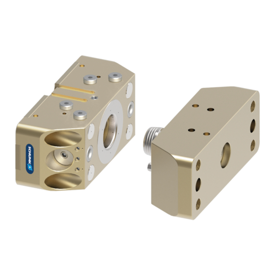
Design and Description 4 Design and Description Design (size NSR-A 100 / 160) Changeover head Clamping pins Pallet adapter Adapter plate (separate accessories) Optional module (separate accessories) Sensors With the NSR-A pneumatic pallet-change system, machine tools can be automatically loaded with pallets. The pallet-change system is made up of a changeover head (1) and a pallet adapter (3) with clamping pin (2). -
Page 24: Application Example For Automated Pallet Loading
Design and Description 4.1 Application example for automated pallet loading The pallet changing system, with the handling system, is the interface between the machine work area and pallet rack. Robot flange Robots Changeover head NSR-A Pallet adapter PKL Clamping pallet Module for stationary use/ application... -
Page 25: Pallet Adapter For Nsr-A 100
Design and Description 4.2 Pallet adapter for NSR-A 100 The PKL 100 pallet adapter was designed as a pallet changing interface for the NSR-A 100 pallet changing system. The pallet adapter provides the connection to the clamping pallet. The pallet adapter has a locating surface and four mounting screws for adapting the clamping pallet. - Page 26 Design and Description Clamping pin NSR-SPA-100 Only DIN EN ISO 4762/12.9 M8 Lag screw mounting screws permissible Mounting surface of clamping pallet Pallet adapter PKL 100 - 90° 06.00 | NSR-A | Assembly and Operating Manual | en | 389722...
- Page 27 Design and Description Mounting surface of clamping pallet Connection interface between the clamping pallet and pallet adapter 06.00 | NSR-A | Assembly and Operating Manual | en | 389722...
-
Page 28: Pallet Adapter For Nsr-A 160
Design and Description 4.3 Pallet adapter for NSR-A 160 The PKL 160 pallet adapter was designed as a pallet changing interface for the NSR-A 160 pallet changing system. External mold inclines are used for position orientation free from play when joining with the pallet changing system. The pallet adapter provides the connection to the clamping pallet. - Page 29 Design and Description Clamping pin SPA 440-16RF Lag screw Only DIN EN ISO 4762/12.9 M16 mounting screws permissible Mounting surface of clamping pallet Pallet adapter PKL 160- 90° 06.00 | NSR-A | Assembly and Operating Manual | en | 389722...
- Page 30 Design and Description Mounting surface of clamping pallet Connection interface between the clamping pallet and pallet adapter 06.00 | NSR-A | Assembly and Operating Manual | en | 389722...
-
Page 31: Coupling Interface For Nsr-A 100 And Nsr-A 160
Torsion resistance for pallet adapter PKL (0°) and PKL (90°), without adapter plate NOTE • Only an original SCHUNK clamping pin may be used on the coupling interface with the designated mounting screws. • Check the screw fitting of the clamping pin at regular intervals to ensure that it is secure. -
Page 32: Assembly
Assembly 5 Assembly 5.1 Assembly requirements Before beginning assembly, request SCHUNK installation drawings Provide air bleed screw for the piston chamber When connecting the pallet changing system, it should be noted that it is only possible to completely ventilate the piston chamber via the air connections during the locking procedure. -
Page 33: Unpacking And Transporting
Check that the delivery is complete and that there is no Ø transport damage. Report every defect to SCHUNK immediately. Carefully transport the pallet changing system to the Ø deployment side using a suitable aid, e. g. a trolley. -
Page 34: Installing And Connecting
Assembly 5.3 Installing and connecting Assembly, dismantling and modification work on the pallet changing system may only be carried out by specialist personnel. WARNING Risk of injury due to unexpected movements! If the power supply is switched on or residual energy remains in the system, components can move unexpectedly and cause serious injuries. - Page 35 Connection and disconnection of transport loads 54]. NOTE • Only mount original SCHUNK clamping pins on the pallet adapter with the prescribed mounting screw. Observe the tightening torque. Clamping pins are available from SCHUNK as a spare part.
-
Page 36: Connections
Assembly 5.4 Connections 5.4.1 Connections to the changeover head on version "without adapter plate" The changeover head is fixed in the installation space with 5 screws. The screws must be tightened with the specified torque Screw tightening torques 47]. Two mounting screws are used as fitting screws for precise positioning on the robot flange. - Page 37 Assembly Unlocking connection on base side Hose-free direct connection Locked connection on base side Mounting groove, "locked" Mounting groove, "unlocked" monitoring (prepared for monitoring (prepared for Mounting thread, pallet magnetic switch MMS 22-SA) magnetic switch MMS 22-SA) presence monitoring (prepared for IN 50 proximity switch) Mounting studs and fitted bushings are used...
- Page 38 Assembly Unlocking connection on base side Locked connection on base side Hose-free direct connection Mounting groove monitoring "open" (for sensor MMS 22-SA) Torsion resistance using fitted bushings Mounting thread Mounting groove monitoring pallet monitoring "tensioned" availability (for sensor IN 50) Torsion resistance (for sensor MMS 22-SA) using mold inclines...
- Page 39 In the dynamic work process, SCHUNK always recommends switching on the locked connection. 06.00 | NSR-A | Assembly and Operating Manual | en | 389722...
-
Page 40: Connections To The Changeover Head On Version "With Adapter Plate
Assembly 5.4.2 Connections to the changeover head on version "with adapter plate" The changeover head has two threads for mounting adapter plates for connecting pneumatic or electrical feed-through modules. These modules are accessories and must be ordered separately. Fitting screw for centering Fitting screw for aligning Pneumatic connections Cylindrical... - Page 41 Assembly Unlocking connection on base side Hose-free direct connection Locked connection on base side Mounting groove, "unlocked" monitoring Mounting groove, "locked" (prepared for magnetic switch MMS 22-SA) monitoring (prepared for magnetic switch MMS 22-SA) Mounting studs and fitted bushings are used to ensure torsion resistance Air outlets for Air outlets for cleaning function...
- Page 42 Assembly Unlocking connection on base side Locked connection on base side Hose-free direct connection Mounting groove monitoring Torsion resistance "open" (for sensor MMS 22-SA) using fitted bushings Mounting groove Mounting thread monitoring monitoring pallet "tensioned" (for availability (for sensor IN 50) sensor MMS 22-SA) Air outlets for cleaning function...
-
Page 43: Unlocking Connection
Assembly 5.4.3 Unlocking connection The clamping system is unlocked if compressed air is constantly applied to the unlocking connection of the pallet changing system. The clamping pallet can be removed or inserted on the clamping station. There is the option of controlling the clamping system either via the M5 air connection hole on the side or a hose-free direct connection on the base side. -
Page 44: Air Purge Connection With Cleaning Function
Assembly 5.4.5 Air purge connection with cleaning function Air purge connection For interface cleaning, the pallet changing system has two side air purge connections with M5 connection thread. without adapter plate The positively driven air flow is released on the centering and locating surfaces of the clamping system. -
Page 45: Pneumatic Circuit Diagram Nsr-A 100
Assembly 5.4.6 Pneumatic circuit diagram NSR-A 100 Pneumatic circuit Pneumatic Actuation using 6 bar circuit symbols (also on base side via diagram without hose-free direct adapter plate connections) 5/3 directional control valve, center position ventilated 3/2 directional control valve Pressure switch Pressure gauge Unlocking connection... -
Page 46: Pneumatic Circuit Diagram Nsr-A 160
Assembly 5.4.7 Pneumatic circuit diagram NSR-A 160 Pneumatic circuit Pneumatic Actuation using circuit symbols diagram without 6 bar (also on base side via adapter plate hose-free direct connections) 5/3 directional control valve, center position ventilated 3/2 directional control valve Pressure switch Pressure gauge Unlocking connection... - Page 47 Assembly 5.5 Screw tightening torques Screws on pallet changing system 5.5.1 Screw tightening torques for NSR-A 100 Item Mounting Strength class Thread Tightening torque [Nm] Quick-change head/ robot flange 12.9 Lag screws 12.9 Pallet adapter / clamping pallet Clamping pin / pallet adapter 12.9 M8 * Countersunk screws...
-
Page 48: Tolerances And Installation Conditions For Clamping Pins In Customer-Specific Pallet Adapters
Installing the clamping pin with the incorrect components, e.g. mounting screws that are too short can lead to significant material damage. Only original SCHUNK clamping pins may be used. These are • available from SCHUNK as a spare part. -
Page 49: Installation Condition For Clamping Pin For Nsr-A 100
Assembly 5.6.1 Installation condition for clamping pin for NSR-A 100 Screw Customer-specific pallet or device Tolerances and installation conditions for clamping pins when installing in a customer-specific pallet adapter > 8 > 13 M8 * > 9 *) Alternative attachment option, Technical data 18]. -
Page 50: Installation Condition For Clamping Pin For Nsr-A 160
Note: If the clamping pin is installed in an aluminum adapter strip, it is essential to install a steel washer under the screw head of the cylindrical screw DIN EN 4762 M16 12.9. The steel washer can be ordered from SCHUNK. *) Alternative attachment option, Technical data 18]. -
Page 51: Installing The Sensors
– The assembly and operating manual and catalog datasheet are included in the scope of delivery for the sensors and are available at schunk.com. • Information on handling sensors is available at schunk.com or from SCHUNK contact persons. 5.7.1 Overview of compatible sensors... -
Page 52: Mount Magnet Sensor Mms 22
Assembly 5.7.2 Mount magnet sensor MMS 22...-SA CAUTION Risk of damage to the sensor during assembly! Observe the maximal tightening torque. • Assembling the sensor MMS 22...-SA The sensors can be set to the following queries: Query "pallet changing system unlocked" Put the pallet changing system in the "unlocked"... -
Page 53: Mounting Inductive Proximity Switch In 50
Assembly 5.7.3 Mounting inductive proximity switch IN 50 CAUTION Risk of damage to the sensor during assembly! Observe the maximal tightening torque. • Mount sensor on the version "without adapter plates" using the inductive proximity switch IN 50, the presence of the clamping pin in the pallet adapter will be queried. -
Page 54: Connection And Disconnection Of Transport Loads
Assembly Secure sensor (2) with nut (1) onto the adapter plate. Ø Secure sensor using counter nut (3). Ø Adjust sensor, see Sensor Assembly and Operating Manual. Ø Query "pallet adapter present" position and test functionality. Ø 5.8 Connection and disconnection of transport loads The following must be taken into account during automated connection and disconnection of transport loads: •... - Page 55 Assembly Position clamping pallet on module for stationary use/application or remove from module for stationary use/application Traverse path of movement axes when loading Clamping pallet 2 x centering taper Module for stationary use/application 1 x centering taper Connect or release the clamping pallet Robot module in unlocked coupling process Connect blast air (cleaning function)
-
Page 56: Troubleshooting
Defective air connections Check air supply Pressure below minimum Check operating pressure (min. 5 bar) A component is broken (e.g. due to Replace the module or send it to SCHUNK for overloading) repair Excess tensile load on clamping pins Reduce support weight... -
Page 57: Maintenance
Only have the cover removed by trained specialist personnel. • In cases of doubt, send the pallet-change system to SCHUNK for repair. 7.1 Maintenance intervals Maintenance interval Maintenance work... -
Page 58: Information On Error-Free Function
Maintenance 7.2 Information on error-free function To ensure the pallet changing system operates perfectly, the following instructions are to be observed: • Pressure medium: compressed air - Observe the requirements for the compressed air supply, ,Technical data 18]. • Make sure that the contact surfaces of the interface are always clean. -
Page 59: Assembly Drawings
Maintenance 7.4 Assembly drawings 7.4.1 Assembly drawings NSR-A 100 06.00 | NSR-A | Assembly and Operating Manual | en | 389722... - Page 60 Maintenance Without adapter plate Sensor system is available to order ** Components are inseparably joined separately as an accessory 06.00 | NSR-A | Assembly and Operating Manual | en | 389722...
- Page 61 Maintenance Adapter plate Sensor system is available to order ** Components are inseparably joined separately as an accessory 06.00 | NSR-A | Assembly and Operating Manual | en | 389722...
-
Page 62: Assembly Drawings Nsr-A 160
Maintenance 7.4.2 Assembly drawings NSR-A 160 06.00 | NSR-A | Assembly and Operating Manual | en | 389722... - Page 63 Maintenance Without adapter plate 06.00 | NSR-A | Assembly and Operating Manual | en | 389722...
- Page 64 Maintenance Adapter plate * Sensor system is available to ** Components are inseparably order separately as an joined accessory 06.00 | NSR-A | Assembly and Operating Manual | en | 389722...
-
Page 65: Translation Of Original Ec Declaration Of Incorporation
Directive 2006/42/EG, Annex II, Part 1.B of the European Parliament and of the Council on machinery. Manufacturer/ SCHUNK GmbH & Co. KG Spann- und Greiftechnik Distributor Bahnhofstr. 106 – 134 D-74348 Lauffen/Neckar We hereby declare that on the date of the declaration the following partly completed machine complied with all basic safety and health regulations found in the directive 2006/42/EC of the European Parliament and of the Council on machinery. -
Page 66: Annex To Declaration Of Incorporation
Annex to Declaration of Incorporation 9 Annex to Declaration of Incorporation according 2006/42/EG, Annex II, No. 1 B 1.Description of the essential health and safety requirements pursuant to 2006/42/EC, Annex I that are applicable and that have been fulfilled with: Product designation Pallet Changing System Type designation NSR-A... - Page 67 Annex to Declaration of Incorporation Protection against mechanical hazards 1.3.6 Risks related to variations in operating conditions 1.3.7 Risks related to moving parts 1.3.8 Choice of protection against risks arising from moving parts 1.3.8.1 Moving transmission parts 1.3.8.2 Moving parts involved in the process 1.3.9 Risks of uncontrolled movements Required characteristics of guards and protective devices...
- Page 68 Annex to Declaration of Incorporation Information 1.7.1 Information and warnings on the machinery 1.7.1.1 Information and information devices 1.7.1.2 Warning devices 1.7.2 Warning of residual risks 1.7.3 Marking of machinery 1.7.4 Instructions 1.7.4.1 General principles for the drafting of instructions 1.7.4.2 Contents of the instructions 1.7.4.3 Sales literature The classification from Annex 1 is to be supplemented from here...
Need help?
Do you have a question about the NSR-A Series and is the answer not in the manual?
Questions and answers