Table of Contents
Advertisement
Available languages
Available languages
Quick Links
Advertisement
Chapters
Table of Contents

Related Manuals for ProLights CROMOBEAM250


Summary of Contents for ProLights CROMOBEAM250
- Page 1 CROMOBEAM250 MOVING HEADS Manuale Utente User Manual...
- Page 2 REV.001-04/11...
-
Page 3: Table Of Contents
5 Appendice 5. 1 Vista esplosa Certificato di garanzia CONTENUTO DELL’IMBALLO: • CROMOBEAM250 • Cavo di sicurezza • Supporti omega (2 pz.) • Manuale utente Music & Lights S.r.l. si riserva ogni diritto di elaborazione in qualsiasi forma delle presenti istruzioni per l’uso. -
Page 4: Avvertenze Generali
CROMOBEAM250 ATTENZIONE! Prima di effettuare qualsiasi operazione con l’unità, leggere con attenzione questo manuale e conservarlo accuratamente per riferimenti futuri. Contiene informazioni importanti riguardo l’installazione, l’uso e la manutenzione dell’unità. SICUREZZA Avvertenze generali • I prodotti a cui questo manuale si riferisce sono conformi alle Direttive della Comunità Europea e pertanto recano la sigla . -
Page 5: Informazioni Generali
CROMOBEAM250 INFORMAZIONI GENERALI Spedizioni e reclami Le merci sono vendute “franco nostra sede” e viaggiano sempre a rischio e pericolo del distributore/cliente. Eventuali avarie e danni dovranno essere contestati al vettore. Ogni reclamo per imballi manomessi dovrà essere inoltrato entro 8 giorni dal ricevimento della merce. -
Page 6: Descrizione E Specifiche Tecniche
CROMOBEAM250 - 1 - DESCRIZIONE E SPECIFICHE TECNICHE 1.1 Elementi di comando e collegamenti Fig.1 MENU ENTER DOWN 8 9 10 11 Vista A Vista B... - Page 7 CROMOBEAM250 1. TESTA MOBILE; flusso d’aria da non ostruire; 2. BRACCIO GIREVOLE; 8. Tasto MENU per chiamare il menu d’imposta- 3. DMX OUT (XLR a 3 poli): zione o tornare ad un livello del menu prece- 1= massa, 2 = DMX -, 3 = DMX +;...
-
Page 8: Descrizione
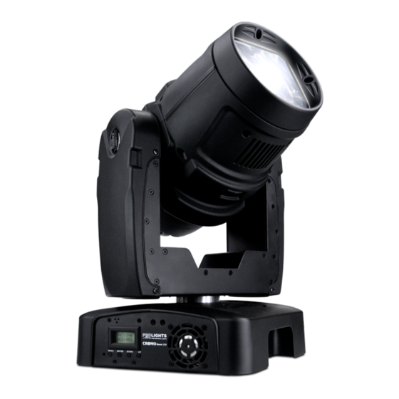
CROMOBEAM250 1.2 DESCRIZIONE CROMOBEAM250 è il primo testa mobile BEAM concepito con sorgente luminosa LED, con l’impiego di un unico potente diodo da 60W. Il gruppo ottico si compone di una speciale lente a superficie liscia, in grado di generare un tubo di luce parallelo e super-concentrato con 6° di ampiezza. La sua emissione di luce è... - Page 9 CROMOBEAM250 • Pan = 2,10° Pan Fine = 0,008° Tilt = 1,05° Tilt Fine = 0,004° • Sospensione e fissaggio: qualsiasi posizione per mezzo di supporti omega (inclusi) Alimentazione • Alimentazione: 100-240V 50/60Hz. • Consumo ad emissione massima: 150W. Peso e dimensioni • Peso: 12,6kg.
-
Page 10: Installazione
- 2 - INSTALLAZIONE 2.1 MONTAGGIO Il CROMOBEAM250 può essere collocato su un piano solido. Inoltre, grazie ai fori di fissaggio, l’unità può essere montata anche a testa in giù, su una traversa (fig.4). Per il fissaggio occorrono dei supporti robusti per il montaggio. -
Page 11: Funzioni E Impostazioni
“reset”. Poco dopo l’unità è pronta. Dopo l’uso spegnere l’unità attraverso il medesimo l’interruttore. 3.2 IMPOSTAZIONE BASE Il proiettore CROMOBEAM250 dispone di un display LCD e di 4 pulsanti per l’accesso alle funzioni del pan- nello di controllo e la loro gestione (fig.5). Welcome... -
Page 12: Struttura Del Menu
CROMOBEAM250 3.3 STRUTTURA DEL MENU Address 001-512 Reset Dmx512 Auto1 Auto2 Sound1 Sound2 Custom Test Intro Slave Basic Channels Advanced 60 Close Display Bright Keylock Info Edition Normal Reverse Normal MENU Tilt Reverse Invert Step Color Linear P/Start (000-255) P/Finish... -
Page 13: Funzionamento In Modalità Stand-Alone
• Sull’unità master selezionare il programma desiderato come indicato nel paragrafo 3.4. • Servirsi dei connettori DMX del CROMOBEAM250 e di un cavo XLR per formare una catena di unità. In certe condizioni e lunghezze si consiglia di effettuare una terminazione come mostrato a pagina 15. -
Page 14: Collegamento
3.7 CONFIGURAZIONE CANALI DMX Il CROMOBEAM250 dispone di 2 configurazioni dei canali DMX a cui si può accedere dal pannello di controllo. • Premere il tasto MENU fino a quando sul display non appare [Intro], quindi premere il tasto ENTER per confermare la scelta. -
Page 15: Costruzione Del Terminatore Dmx
DMX per il primo canale DMX. Se, per esempio, sull’unità di comando è previsto l’indirizzo 33 per co- mandare la funzione del primo canale DMX, si deve impostare sul CROMOBEAM250 l’indirizzo di start 33. Le altre funzioni del pannello saranno assegnate automaticamente agli indirizzi successivi. Segue un esempio... -
Page 16: Tabella Canali Dmx
CROMOBEAM250 3.12 TABELLA CANALI DMX Channel Function in BASIC mode Channel Function in BASIC mode value value STROBE 0 - 540° 000-255 Close 000-031 Open 032-063 TILT Strobe: Slow > Fast 064-095 Open 096-127 000-255 0-270° Pulse strobe effect: COLOR WHEEL Slow >Fast... - Page 17 CROMOBEAM250 Channel Function in ADVANCED mode Channel Function in ADVANCED mode value value GOBO WHEEL ROTATION 0 - 540° 000-255 360° indexing 000-060 Clockwise rotate: PAN FINE slow to fast 061-150 Non function 151-165 Fine control of pan movement 000-255...
-
Page 18: Programmazione Personalizzata
• Scegliere il valore desiderato per il parametro servendosi dei tasti UP e DOWN e confermare l’imposta- zione premendo il tasto ENTER. Il CROMOBEAM250 eseguirà tutti gli “step” nella modalità [Custom] (vedi paragrafo 3.4 Funzionamento in modalità Stand-alone) e poi si fermerà. Qualora si voglia effettuare un ciclo continuo è necessario aggiun- gere un ultimo passo (step), la cui durata deve essere pari a 0 secondi. - Page 19 CROMOBEAM250 Funzione Range • Premere il tasto MENU fino a quando sul display non appare [Range], quindi premere il tasto ENTER per confermare la scelta. • Con i tasti UP e DOWN selezionare il parametro che si desidera modificare fra [P/start], [P/finish], [T/start], [T/finish] e premere ENTER.
- Page 20 CROMOBEAM250 Funzione Keylock • Premere il tasto MENU fino a quando sul display non appare [Intro], quindi premere il tasto ENTER per confermare la scelta. • Premere i tasti UP e DOWN per selezionare nel menu la voce [Keylock] e confermare la scelta premendo il tasto ENTER.
-
Page 21: Manutenzione
CROMOBEAM250 - 4 - MANUTENZIONE 4.1 PULIZIA SISTEMA OTTICO E MANUTENZIONE • Durante gli interventi, assicurarsi che l’area sotto il luogo di installazione sia libera da personale non qualificato. • Spegnere l’unità, scollegare il cavo di alimentazione ed aspettare finché l’unità non si sia raffreddata. -
Page 22: Sostituzione Gobos
CROMOBEAM250 4.3 SOSTITUZIONE GOBOS I gobos rotanti, nella ruota, possono essere cambiati e sostituiti, per esempio, con propri gobos: 1. Staccare la spina dalla presa di rete. 2. Svitare le viti per togliere la copertura frontale (16) e posteriore (17) e successivamente la parte superiore (18) e inferiore (19) della testa mobile. -
Page 23: Sostituzione Fusibile
CROMOBEAM250 4.4 SOSTITUZIONE FUSIBILE 1. Assicurarsi di scollegare il cavo di alimentazione del proiettore prima di sostituire un fusibile bruciato con uno dello stesso tipo e valore. 2. Con un cacciavite, rimuovere il portafusibile dalla sua sede e il fusibile bruciato dal suo supporto; sosti- tuire il fusibile con uno identico per tipologia e valore. -
Page 24: Appendice
CROMOBEAM250 - 5 - APPENDICE 5.1 VISTA ESPLOSA 18 19 ITEM ITEM ITEM Head cover Power socket Lenses Back cover Power input Motor XLR Plug (male/female) Head cover Motor driver board Rotation gobo wheel Motor Power switch Color wheel Pan belt... -
Page 27: Cromobeam250
4. 2 Fuse replacement 5 Appendix 5. 1 Exploded view Warranty PACKING CONTENT: • CROMOBEAM250 • Safety cable • Omega kit (2 pc.) • User manual All rights reserved by Music & Lights S.r.l. No part of this instruction manual may be. -
Page 28: General Instructions
CROMOBEAM250 WARNING! Before carrying out any operations with the unit, carefully read this instruction manual and keep it with cure for future reference. It contains important information about the installation, usage and maintenance of the unit. SAFETY General instructions • The products referred to in this manual conform to the European Community Directives and are therefore marked with . -
Page 29: General Information
CROMOBEAM250 GENERAL INFORMATION Shipments and claims The goods are sold “ex works” and always travel at the risk and danger of the distributor. Eventual damage will have to be claimed to the freight forwarder. Any claim for broken packs will have to be forwarded within 8 days from the reception of the goods. -
Page 30: Description And Technical Specifications
CROMOBEAM250 - 1 - DESCRIPTION AND TECHNICAL SPECIFICATIONS 1.1 Operating elements and connections Fig.1 MENU ENTER DOWN 8 9 10 11 A view B view... - Page 31 CROMOBEAM250 1. MOVING HEAD; 8. MENU button: exits from the current menu or 2. ROTARY ARM; function; 3. DMX OUT (3-pole XLR): 9. ENTER button: enables the currently displayed 1= ground, 2 = DMX -, 3 = DMX +; menu or sets the currently selected value into 4.
-
Page 32: Description
CROMOBEAM250 1.2 DESCRIPTION CROMOBEAM250 is the first BEAM moving head based on LED light source, housing a high-power 60W diode. The optical unit is composed by a special smooth-surface lens, featuring a 6° highly concentrated parallel beam. Its light output can be compared to a MSR575 luminaire with Iris effect enabled. The amazing rapid movements and the absence of noise make CROMOBEAM250 the perfect device to generate effect in the air, replacing the traditional long-throw projectors and the ACL parsets in medium sized light-shows. - Page 33 CROMOBEAM250 Power supply • Power unit: 100-240V 50/60Hz. • Max power consumption: 150W. Weight and dimensions • Weight: 12,6kg • Dimensions: 280x329x545mm. Fig.3...
-
Page 34: Installation
- 2 - INSTALLATION 2.1 MOUNTING The CROMOBEAM250 may be set up on a solid and even surface. By means of the fixing facilities of the base plate, the unit can also be mounted upside down to a cross arm. The base plate is shown in fig.4. For fixing, stable mounting clips are required. -
Page 35: Functions And Settings
(6) . Shortly after that the CROMOBEAM250 is ready for operation. After operation, switch off the unit with the power switch. 3.2 BASIC The CROMOBEAM250 has a LCD display and 4 button used to access the control panel functions and man- age them (fig.5). Welcome... -
Page 36: Menu Structure
CROMOBEAM250 3.3 MENU STRUCTURE Address 001-512 Reset Dmx512 Auto1 Auto2 Sound1 Sound2 Custom Test Intro Slave Basic Channels Advanced 60 Close Display Bright Keylock Info Edition Normal Reverse Normal MENU Tilt Reverse Invert Step Color Linear P/Start (000-255) P/Finish (000-255) -
Page 37: Operation In Stand-Alone Mode
CROMOBEAM250 Step (001-255) (000-255) Tilt (000-255) Speed (000-255) Color (000-255) Gobo1 (000-255) Edit Gobo1 Rot (000-255) Dimmer (000-255) Strobe (000-255) MENU Time (000-255) Default Default 3.4 OPERATION IN STAND-ALONE MODE If no DMX control signal is present at the jack DMX INPUT (3), and the unit independently runs through its show programme. -
Page 38: Linking
• Press the UP and DOWN buttons to select [Channels] menu voice and confirm the choice by pressing the ENTER button. • Select a DMX configuration: [Basic] or [Adavnced], and press ENTER button. The tables on page 12 indicate the operating mode and DMX value. The CROMOBEAM250 is equipped with 3-pole XLR connections. 3.8 DMX MODE • Press the MENU button and select, via the directional buttons, the [Intro] menu choice, then press the... -
Page 39: Construction Of The Dmx Termination
3.11 ADJUSTING THE START ADDRESS To able to operate the CROMOBEAM250 with a light controller, adjust the DMX start address for the first a DMX channel. If e. g. address 33 on the controller is provided for controlling the function of the first DMX channel, adjust the start address 33 on the CROMOBEAM250. -
Page 40: Dmx Control
CROMOBEAM250 3.12 DMX CONTROL Channel Function in BASIC mode Channel Function in BASIC mode value value STROBE 0 - 540° 000-255 Close 000-031 Open 032-063 TILT Strobe: Slow > Fast 064-095 Open 096-127 000-255 0-270° Pulse strobe effect: COLOR WHEEL Slow >Fast... - Page 41 CROMOBEAM250 Channel Function in ADVANCED mode Channel Function in ADVANCED mode value value GOBO WHEEL ROTATION 0 - 540° 000-255 360° indexing 000-060 Clockwise rotate: PAN FINE slow to fast 061-150 Non function 151-165 Fine control of pan movement 000-255...
-
Page 42: Edit Custom
• Enter [Use] and select [Yes] to run the steps user need. CROMOBEAM250 will execute all the steps in the custom program and it will stop. To make the fixture to start over add a last step whose duration is 0 second. - Page 43 CROMOBEAM250 Range function • Press the MENU button, select the [Range] menu voice and press the ENTER button to confirm the choice. • Select the parameter to be changed between [P/start], [P/finish], [T/start] and [T/finish]; press the ENTER button to confirm.
- Page 44 CROMOBEAM250 Keylock function • Press the MENU button and select, via the directional buttons, the [Intro] menu choice, then press the ENTER button to confirm the choice. • Press the UP and DOWN buttons to select [Keylock] menu voice and confirm the choice by pressing the ENTER button.
-
Page 45: Maintenance
CROMOBEAM250 - 4 - MAINTENANCE 4.1 CLEANING THE UNIT AND MAINTENANCE • Make sure the area below the installation place is free from unwanted persons during setup. • Switch off the unit, unplug the main cable and wait until the unit has cooled down. -
Page 46: Replacement Of The Gobos
CROMOBEAM250 4.3 REPLACEMENT OF THE GOBOS The rotating gobos can be replaced and e. g. be exchanged for individual gobos. 1. Disconnect the main plug from the socket. 2. Release the screws and remove the part (16), (17) and then the part (18), (19) of the pan head. -
Page 47: Fuse Replacement
CROMOBEAM250 4.4 FUSE REPLACEMENT 1. With a flat head screwdriver, wedge the fuse holder out of its housing and remove the blown fuse from its holder. 2. Replace the blown fuse with a fuse of the exact same type and rating. -
Page 48: Appendix
CROMOBEAM250 - 5 - APPENDIX 5.1 EXPLODED VIEW 18 19 ITEM ITEM ITEM Head cover Power socket Lenses Back cover Power input Motor XLR Plug (male/female) Head cover Motor driver board Rotation gobo wheel Motor Power switch Color wheel Pan belt... - Page 49 Place Stamp Here Affrancare Spett.le Music&Lights S.r.l. Via Appia Km 136.200 04020 Itri (LT) Italy "...
- Page 52 Music & Lights S.r.l. entertainment technologies Via Appia Km 136,200 - 04020 Itri (LT) ITALY ISO 9001:2008 tel. +39 0771 72190 fax +39 0771 721955 Certified Company www.musiclights.it info@musiclights.it...
Need help?
Do you have a question about the CROMOBEAM250 and is the answer not in the manual?
Questions and answers