Advertisement

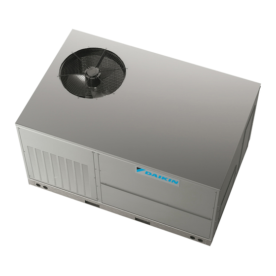
DSC/DSH
LIGHT COMMERCIAL
3
5 T
TO
ON
ATTENTION INSTALLING PERSONNEL:
Prior to installation, thoroughly familiarize yourself with this
Installation Manual. Observe all safety warnings. During
installation or repair, caution is to be observed.
It is your responsibility to install the product safely and to
educate the customer on its safe use.
RECOGNIZE THIS SYMBOL
AS A SAFETY PRECAUTION.
These installation instructions cover the outdoor installation
of single package heating and cooling units. See the
Specification Sheet applicable to your model for information
regarding accessories.
*NOTE: Please contact your distributor or our website for the
applicable Specification Sheet referred to in this manual.
Our continuing commitment to quality products may mean a change in specifications without notice.
IOD-1023D
04/2019
SERIES
PACKAGED HEATING AND COOLING UNIT
© 2016 - 2017, 2019
5151 San Felipe St., Suite 500, Houston, TX 77056
www.daikinac.com
INSTALLATION INSTRUCTIONS
O
NLY PERSONNEL THAT HAVE BEEN TRAINED TO INSTALL
(
, "
")
HEREINAFTER
SERVICE
THE EQUIPMENT SPECIFIED IN THIS MANUAL SHOULD
. T
SERVICE THE EQUIPMENT
HE MANUFACTURER WILL NOT BE RESPONSIBLE FOR ANY
INJURY OR PROPERTY DAMAGE ARISING FROM IMPROPER SERVICE OR SERVICE
. I
PROCEDURES
F YOU SERVICE THIS UNIT
INJURY OR PROPERTY DAMAGE WHICH MAY RESULT
THAT REQUIRE ONE OR MORE LICENSES TO SERVICE THE EQUIPMENT SPECIFIED IN THIS
,
MANUAL
ONLY LICENSED PERSONNEL SHOULD SERVICE THE EQUIPMENT
,
,
INSTALLATION
ADJUSTMENT
SERVICING OR REPAIR OF THE EQUIPMENT SPECIFIED IN
,
THIS MANUAL
OR ATTEMPTING TO INSTALL
EQUIPMENT SPECIFIED IN THIS MANUAL WITHOUT PROPER TRAINING MAY RESULT IN
,
PRODUCT DAMAGE
PROPERTY DAMAGE
Cancer and Reproductive Harm
www.P65Warnings.ca.gov
Replacement Parts ................................................................ 2
Safety Instructions ................................................................ 2
General Information ............................................................. 2
Unit Location ........................................................................ 3
Clearances ............................................................................ 4
Roof Curb Post-Installation Checks ....................................... 5
Roof Top Duct Connections ................................................... 5
Rigging Details ...................................................................... 5
Electrical Wiring .................................................................... 6
Circulating Air and Filters ...................................................... 8
Condensate Drain Connection .............................................. 8
Startup, Adjustments, and Checks ........................................ 9
Air Flow Adjustments ......................................................... 10
,
,
ADJUST
SERVICE OR REPAIR
,
YOU ASSUME RESPONSIBILITY FOR ANY
. I
,
N ADDITION
IN JURISDICTIONS
. I
,
,
ADJUST
SERVICE OR REPAIR THE
,
.
PERSONAL INJURY OR DEATH
-
Index
MPROPER

Advertisement

Table of Contents
loading

Summary of Contents for Daikin DSC Series

  • Page 1: Table Of Contents

    INSTALLATION INSTRUCTIONS DSC/DSH SERIES LIGHT COMMERCIAL PACKAGED HEATING AND COOLING UNIT NLY PERSONNEL THAT HAVE BEEN TRAINED TO INSTALL ADJUST SERVICE OR REPAIR , “ ”) HEREINAFTER SERVICE THE EQUIPMENT SPECIFIED IN THIS MANUAL SHOULD SERVICE THE EQUIPMENT HE MANUFACTURER WILL NOT BE RESPONSIBLE FOR ANY INJURY OR PROPERTY DAMAGE ARISING FROM IMPROPER SERVICE OR SERVICE PROCEDURES F YOU SERVICE THIS UNIT...
  • Page 2: Replacement Parts

    AND IT IS NECESSARY THAT THE INSTALLER AND SERVICE PERSONNEL EXERCISE CAUTION specification sheet for light commercial models. Specification sheets can be found at www.daikinac.com for Daikin brand products. Within the website, please select the commercial products menu and then select the submenu for the type of...
  • Page 3: Unit Location

    EPA R carrier. The carrier is responsible for making prompt EGULATIONS inspection of damage and for a thorough investigation (EPA) MPORTANT NITED TATES NVIRONMENTAL ROTECTION GENCY of each claim. The distributor or manufacturer will not HAS ISSUED VARIOUS REGULATIONS REGARDING THE INTRODUCTION AND DISPOSAL accept claims from dealers for transportation damage.
  • Page 4: Clearances

    plumbing vent outlet. For specific distances required, sembly of the sheet metal curb is included in the curb accessory. consult local codes. • Allow minimum clearances from the enclosure for fire WARNING protection, proper operation, and service access (see Unit Clearances).
  • Page 5: Roof Curb Post-Installation Checks

    Flexible duct connectors between the unit and ducts are recom- to facilitate possible fan shaft, coil, and electric heat. A clearance mended. Insulate and weatherproof all external ductwork and of 48” is recommended on all other sides of the unit to facilitate joints as required and in accordance with local codes.
  • Page 6: Electrical Wiring

    accomplished by extracting the sheet metal retainers and pulling the struts through the base of the unit. Refer to CAUTION rigging label on the unit. Important: If using bottom discharge with roof curb, ductwork O PREVENT SEVERE DAMAGE TO THE BOTTOM OF THE UNIT DO NOT should be attached to the curb prior to installing the unit.
  • Page 7 MAIN POWER The main power supply wiring to the unit and low voltage wiring LOW VOLTAGE to accessory controls must be done in accordance with these in- BLOCK structions, the latest edition of the National Electrical Code (ANSI/ NFPA 70), and all local codes and ordinances. The unit is factory wired for the voltage shown on the unit’s data plate.
  • Page 8: Circulating Air And Filters

    control wiring runs not exceeding 200 feet. Low voltage NITS INSTALLED ON wiring may be National Electrical Code (NEC) Class 2 where Main power and low voltage wiring may enter the unit through permitted by local codes. the condenser end or through the roof curb. Install conduit con- 4.
  • Page 9: Startup, Adjustments, And Checks

    WARNING Base Rail MOVING MACHINERY HAZARD! O PREVENT POSSIBLE PERSONAL INJURY OR DEATH DISCONNECT Open Vent 2” Min “OFF” POWER TO THE UNIT AND PADLOCK IN THE POSITION BEFORE SERVICNG FANS EATING TARTUP See NOTE On new installations, or if a major component has been replaced, the operation of the unit must be checked.
  • Page 10: Air Flow Adjustments

    Remove any extraneous construction and shipping materials that If an economizer is installed, check the unit operating balance with may be found during this procedure. Rotate all fans manually to the economizer at full outside air and at minimum outside air. check for proper clearances and that they rotate freely.
  • Page 11 light. Refer to Appendices A and B for basic unit fan RPM. Refer & V HEAVES DJUSTMENT also to “Airflow” section of this manual. With disconnect switch 1. Loosen set screw “B” using a 5/32" Allen key. open, disconnect thermostat wires from terminals Y and W. This 2.
  • Page 12 to “Auto” and turn temperature setting as high as it will the unit trips. 13. If unit operates properly in the heating cycle, raise the temperature setting until the heating second stage makes 2. Inspect all registers and set them to the normal open contact.
  • Page 13 por condenses to liquid. It then goes through the expansion de- ure of the heat pump, such as a compressor, or refrigerant leak, vice to the outdoor coil (condenser on the cooling cycle) where etc. the liquid is evaporated, and the vapor goes to the compressor. Since the temperature of the refrigerant in the outdoor coil on the When the solenoid valve coil is operated either from heating to heating cycle is generally below freezing point, frost forms on the...
  • Page 14 should be cleaned or replaced. These few steps will help to keep UTSIDE IR INTO ETURN the product up time to a maximum. The Service section that fol- Do not introduce cold outside air into the return duct of a heat lows should help in identifying problems if the unit does not oper- pump installation.
  • Page 15 APPENDIX A BLOWER PERFORMANCE TABLES DIRECT DRIVE STANDARD DOWN SHOT AND HORIZONTAL DSC/DSH036 DIRECT DRIVE DOWN SHOT EXTERNAL STATIC STANDARD SPEED TAP PRESSURE (ESP) AMPS WATTS in w.c. 0.10 1270 1.53 0.20 1205 1.53 0.30 1145 1.49 0.40 1085 1.45 0.50 1035 1.42...
  • Page 16 APPENDIX A BLOWER PERFORMANCE TABLES DIRECT DRIVE STANDARD DOWN SHOT AND HORIZONTAL DSC/DSH048 DIRECT DRIVE DOWN SHOT EXTERNAL STATIC STANDARD SPEED TAP PRESSURE (ESP) AMPS WATTS in w.c. 0.10 1548 2.03 0.20 1500 2.00 0.30 1425 1.89 0.40 1353 1.83 0.50 1273 1.75...
  • Page 17 APPENDIX A BLOWER PERFORMANCE TABLES DIRECT DRIVE STANDARD DSC060 DOWN SHOT DIRECT DRIVE DOWN SHOT EXTERNAL STATIC SPEED STANDARD PRESSURE (ESP) AMPS WATTS in w.c. 0.10 1205 1.47 0.20 1150 1.54 0.30 1065 1.59 0.40 1.68 0.50 1.79 0.60 1.82 0.10 1375 1.94...
  • Page 18 APPENDIX A BLOWER PERFORMANCE TABLES DIRECT DRIVE STANDARD DSC060 HORIZONTAL DIRECT DRIVE HORIZONTAL EXTERNAL STATIC SPEED STANDARD PRESSURE (ESP) AMPS WATTS in w.c. 1215 1.40 1150 1.46 1085 1.54 1010 1.64 1.74 1.77 1395 1.86 1325 1.95 1260 2.01 1210 2.10 1135 2.16...
  • Page 19 APPENDIX A BLOWER PERFORMANCE TABLES DIRECT DRIVE DSH060 HORIZONTAL DSH060****D DIRECT DRIVE HORIZONTAL EXTERNAL STATIC SPEED STANDARD PRESSURE (ESP) AMPS WATTS in w.c. 1225 1.40 1170 1.46 1085 1.54 1015 1.62 1.74 1.77 1425 1.80 1330 1.96 1260 2.00 1210 2.10 1135 2.16...
  • Page 20 APPENDIX A BLOWER PERFORMANCE TABLES DIRECT DRIVE DSH060 DOWNSHOT DSH060****D DIRECT DRIVE DOWNSHOT EXTERNAL STATIC SPEED STANDARD PRESSURE (ESP) AMPS WATTS in w.c. 1205 1.47 1150 1.54 1065 1.59 1.68 1.79 1.82 1375 1.94 1300 2.01 1230 2.05 1180 2.15 1100 2.22 1005...
  • Page 21 APPENDIX A BLOWER PERFORMANCE TABLES BELT DRIVE STANDARD DOWN SHOT DSC/DSH036 STANDARD BELT DRIVE DOWN SHOT TURNS OPEN (In. W.C.) 1358 0.32 1210 0.24 1203 0.29 1044 0.23 1209 0.34 1044 0.27 0.22 1320 0.34 1050 0.31 0.24 0.20 1317 0.37 1124 0.31...
  • Page 22 APPENDIX A BLOWER PERFORMANCE TABLES BELT DRIVE HIGH STATIC DOWN SHOT DSC/DSH036 HIGH STATIC DOWNSHOT TURNS OPEN (In. W.C.) 1240 0.44 1124 0.43 1225 0.48 0.39 1063 1280 0.55 0.44 0.37 1143 0.52 0.40 1268 0.59 0.48 0.36 1347 1127 0.69 0.55 0.43...
  • Page 23 APPENDIX A BLOWER PERFORMANCE TABLES BELT DRIVE STANDARD HORIZONTAL DSC/DSH036 STANDARD BELT DRIVE HORIZONTAL TURNS OPEN (In. W.C.) 1375 0.28 1367 0.33 1186 0.27 1374 0.39 1186 0.31 0.25 1193 0.36 0.28 0.23 1277 0.36 0.34 0.26 1312 0.39 1056 0.33 0.31 1126...
  • Page 24 APPENDIX A BLOWER PERFORMANCE TABLES BELT DRIVE HIGH STATIC HORIZONTAL DSC/DSH036 HIGH STATIC HORIZONTAL TURNS OPEN (In. W.C.) 1459 0.51 1322 0.50 1136 1392 0.55 0.46 1208 1455 0.63 0.51 0.43 1299 0.40 0.60 0.46 1409 1094 0.65 0.54 0.41 1480 1252 0.76...
  • Page 25 APPENDIX A BLOWER PERFORMANCE TABLES BELT DRIVE HIGH STATIC DOWN SHOT DSH060 HIGH STATIC DOWNSHOT TURNS OPEN (In. W.C.) CFM 2021 0.87 1854 0.72 2138 0.91 1928 0.83 1760 0.69 2017 0.87 1813 0.80 1623 0.66 2110 0.97 1897 0.83 1690 0.78 1486...
  • Page 26 ECONOMIZER-AIRSIDE PRESSURE DROP Airflow Pressure Drop of Downflow Economizer for 3 to 6 Ton Rooftop Units (100% Return Air) SCFM 1000 1200 1400 1600 1800 2000 2200 2400 2600 2800 in. WG 0.02 0.04 0.05 0.07 0.09 0.12 0.14 0.17 0.21 0.24 0.28...
  • Page 27 APPENDIX B ELECTRICAL DATA Compressor Optional Powered Electrical Outdoor Fan Motor Indoor Fan Motor Optional Electric Heat Power Supply Model Number Circuit 1 Convienience Outlet Rating Type Part # 24.7 / 24.7 40 / 40 EHK1-10 7.5 / 10.0 36.1 / 41.7 48.2 / 55.2 50 / 60 Standard -...
  • Page 28 APPENDIX B ELECTRICAL DATA Compressor Optional Powered Electrical Outdoor Fan Motor Indoor Fan Motor Optional Electric Heat Power Supply Model Number Circuit 1 Convienience Outlet Rating Type Part # 10.0 EHK4-10 12.0 24.6 Standard - EHK4-15 15.0 18.0 32.1 DSH036XXX4B 460-3-60 38.0 0.25...
  • Page 29 APPENDIX B ELECTRICAL DATA Compressor Optional Powered Electrical Outdoor Fan Motor Indoor Fan Motor Optional Electric Heat Power Supply Model Number Circuit 1 Convienience Outlet Rating Type Part # 10.0 EHK7-10 10.0 15.4 15.0 EHK7-15 15.1 21.8 Standard & 18.0 EHK7-18 18.1 25.5...
  • Page 30 APPENDIX B ELECTRICAL DATA Compressor Optional Powered Electrical Outdoor Fan Motor Indoor Fan Motor Optional Electric Heat Power Supply Model Number Circuit 1 Convienience Outlet Rating Type Part # 41.3 / 41.3 60 / 60 EHK1-10 7.5 / 10.0 36.1 / 41.7 53.8 / 60.8 60 / 70 EHK1-15...
  • Page 31 APPENDIX B ELECTRICAL DATA Compressor Optional Powered Electrical Outdoor Fan Motor Indoor Fan Motor Optional Electric Heat Power Supply Model Number Circuit 1 Convienience Outlet Rating Type Part # 40.2 / 40.2 60 / 60 EHK1-10 7.5 / 10.0 36.1 / 41.7 85.3 / 92.3 90 / 100 EHK1-15...
  • Page 32 APPENDIX C UNIT DIMENSIONS Model X (in.) DSC036 DSH036 38 13/16 DSC048 DSH048 47 1/2” DSC060 DSH060 42 13/16 73 1/4” 74 1/16” *6 Ton - 42 13/16 48 3/16” 11” 19 7/16” 4 7/8” RETURN 17” 7 3/8” DRAIN THRU CURB EMBOSS RETURN...
  • Page 33 APPENDIX D WIRING DIAGRAMS WIRING DIAGRAMS DSC036*/DSC048* THREE PHASE 208-230V/3/60HZ DIRECT DRIVE EBTDR XFMR-R XFMR-C NOTE #2 SPEED YL/PK PLF 2 PLF 1 CONTROL BOX BL/PK 3 SPE E D YL/PK ALTERNATE 3 SPE E D MOTOR COMP 6-WIRES SMOKE/FIRE DETECTOR SEE TABLE 1 REPLACES JUMPER COMPONENT LEGEND...
  • Page 34 WIRING DIAGRAMS DSC060* THREE PHASE 208/230V/3/60HZ DIRECT DRIVE NOTE 3 NOTE 4 YL/PK PLF 2 LVJB TB 1 RCCF SEE NOTE 2 PLF 1 CONTROL BOX YL/PK BL/PK COMP SMOKE/FIRE DETECTOR REPLACES JUMPER COMPONENT LEGEND FACTORY WIRING LINE VOLTAGE CONTACTOR SUPPLY VOLTAGE LOW VOLTAGE CONDEN SER MOTOR...
  • Page 35 WIRING DIAGRAMS DSC036*/DSC048*/DSC060* THREE PHASE 208-230V/460/575V/3/60HZ BELT DRIVE 24 0 20 8 46 0 57 5 EBTDR XFMR-R XFMR-C NOTE #2 NOTE #2 SPEED YL/PK PLF 2 LVJB RCCF PLF 1 RD OR CONTROL BOX YL/PK BL/PK COMP SMOKE/FIRE DETECTOR REPLACES JUMPER COMPONENT LEGEND FACTOR Y WIRING...
  • Page 36 WIRING DIAGRAMS DSH036*/DSH048* THREE PHASE 208-230V/3/60HZ DIRECT DRIVE EBTD R XFMR-R XFMR-C NOTE #2 SPEED SE E NO TE 4 GN D PLF 2 CC R CON TRO L LVD R 0-RV LVJB C-RV HVDR TB 1 PLF 1 SMOKE/FIREDETECT OR REPLACESJUMPER BL/PK B L/PK...
  • Page 37 WIRING DIAGRAMS DSH060* THREE PHASE 208-230V/3/60HZ DIRECT DRIVE SEE NOTE 3 NOTE 4 PLF 2 LVDR 0-RV LVJB C-RV PLF 1 HVD R RCCF SEE NOTE 2 BL/PK BL/PK COMP COMPONENT LEGEND FACTO RY W IRIN G CONTACTOR LINE VOLTAG E COMPRESSO R CONTACTOR RELAY LOW VOLTAG E SUPPLY VOLTAGE...
  • Page 38 WIRING DIAGRAMS DSH036*/DSH048*/DSH060* (B) THREE PHASE 208-230V/3/60HZ BELT DRIVE SEE NOTE 4 EBTD R XFMR-R XFMR-C SEENOTE 2 SPEED PLF2 LVD R 0-RV C-RV RCCF HVDR PLF1 REPLACE JUMPER WITH SMOK E/FIRE BL/PK DETECTOR BL/PK COMP SEE NO TE 5 COMPONENT LEGEND SUPPL Y VOLTA GE BLOWER CONTACTOR...
  • Page 39 WIRING DIAGRAMS DSH036* (4B/7B)/DSH048* (4B/7B)/DSH060* (4B/7B) THREE PHASE 460/575V/3/60HZ BELT DRIVE EBTDR XFMR-R XFMR-C SPEED NOTE 2 YL/PK PLF 2 YL/PK LVDR 0-RV C-RV HVDR RCCF PLF 1 SEE NOTE 4 BL/PK BL/PK REPLACE JUMPER WITH SMOKE / FIRE DETECTOR COMP SEE NOTE 4 COMPONENT LEGEND...
  • Page 40 WIRING DIAGRAMS DSC036* /DSC048* SINGLE PHASE 208-230V/1PH/60HZ DIRECT DRIVE EBTDR XFMR-R XFMR-C NOTE #2 SPEED YL/PK RCCF PLF 1 CONTROL BL/PK 3 SPEED YL/PK 3 SPEED SMOKE/FIRE ALTERNATE DETECTOR MOTOR COMP REPLACES 6-WIRES JUMPER SEE TABLE 1 COMPONENT LEGEND FACTORY WIRING BLOWER CAPACITOR LINE VOLTAGE SUPPLY VOLTAGE...
  • Page 41 WIRING DIAGRAMS DSC060* SINGLE PHASE 208-230V/1PH/60HZ DIRECT DRIVE NOTE 3 NOTE 4 YL/PK PLF 2 NOTE 5 LVJB RCCF SEE NOTE 2 PLF 1 CONTROL BOX YL/PK BL/PK COMP SMOKE/FIRE DETECTOR REPLACES JUMPER FACTORY WIRING COMPONENT LEGEND LIN E VOLTAGE SUPPLY VOLTAGE L OW VOLTAGE CONTACTOR...
  • Page 42 WIRING DIAGRAMS DSH036*/DSH048* SINGLE PHASE 208-230V/1PH/60HZ DIRECT DRIVE SEE NOTE 8 SEE NOTE 9 SEE NOTE 7 EBTDR XFMR-R XFMR-C NOTE #2 SPEED SEE NOTE 2 YL/PK YL/PK PLF 2 LVDR SEE NOTE 7 0-RV LVJB C-RV HVDR RCCF PLF 1 CONTROL BOX SMOKE/FIRE DETECTOR...
  • Page 43 WIRING DIAGRAMS DSH060* SINGLE PHASE 208-230V/1PH/60HZ DIRECT DRIVE NOTE 7 LVD R 0-RV LVJB C-RV HVD R RCCF CONTROL SEE NOTE 2 REPLACE BL/PK JUMPER WITH SMOKE/FIRE DETECTOR NOTE 6 COMP ONENT LEG EN D FA CTO RY W IRING LI NE VO LT A G E CON TAC TOR SUPPLY V OLTAGE...
  • Page 44 WIRING DIAGRAMS FOR MODELS WITH DDC CONTROLS For complete information and installation instructions for models with DDC controls, see manual DK-DDC-TGD-XXX.
  • Page 45 WIRING DIAGRAMS DSC036/DSC048*** [208-230V/3/60] D*** Wiring is subject to change. Always refer to the wiring diagram on the unit for the most up-to-date wiring.
  • Page 46 WIRING DIAGRAMS DSC036/DSC048*** [208-230V/3/60] D*** Wiring is subject to change. Always refer to the wiring diagram on the unit for the most up-to-date wiring.
  • Page 47 WIRING DIAGRAMS DSC060*** [208-230V/3/60]D*** Wiring is subject to change. Always refer to the wiring diagram on the unit for the most up-to-date wiring.
  • Page 48 WIRING DIAGRAMS DSC060*** [208-230V/3/60]D*** Wiring is subject to change. Always refer to the wiring diagram on the unit for the most up-to-date wiring.
  • Page 49 WIRING DIAGRAMS DSH036/DSH048*** [208-230V/3/60] D*** Wiring is subject to change. Always refer to the wiring diagram on the unit for the most up-to-date wiring.
  • Page 50 WIRING DIAGRAMS DSH036/DSH048*** [208-230V/3/60] D*** Wiring is subject to change. Always refer to the wiring diagram on the unit for the most up-to-date wiring.
  • Page 51 WIRING DIAGRAMS DSH060*** [208-230V/3/60] D*** Wiring is subject to change. Always refer to the wiring diagram on the unit for the most up-to-date wiring.
  • Page 52 WIRING DIAGRAMS DSH060*** [208-230V/3/60] D*** Wiring is subject to change. Always refer to the wiring diagram on the unit for the most up-to-date wiring.
  • Page 53 WIRING DIAGRAMS DSC036/DSC048/DSC060*** [208-230V,460V,575V,/3/60]B*** Wiring is subject to change. Always refer to the wiring diagram on the unit for the most up-to-date wiring.
  • Page 54 WIRING DIAGRAMS DSC036/DSC048/DSC060*** [208-230V,460V,575V,/3/60]B*** Wiring is subject to change. Always refer to the wiring diagram on the unit for the most up-to-date wiring.
  • Page 55 WIRING DIAGRAMS DSH036/DSH048/DSH060*** [208-230V/3/60] B*** Wiring is subject to change. Always refer to the wiring diagram on the unit for the most up-to-date wiring.
  • Page 56 WIRING DIAGRAMS DSH036/DSH048/DSH060*** [208-230V/3/60] B*** Wiring is subject to change. Always refer to the wiring diagram on the unit for the most up-to-date wiring.
  • Page 57 WIRING DIAGRAMS DSH036/DSH048/DSH060*** [460V,575V/3/60] B*** Wiring is subject to change. Always refer to the wiring diagram on the unit for the most up-to-date wiring.
  • Page 58 WIRING DIAGRAMS DSH036/DSH048/DSH060*** [460V,575V/3/60] B*** Wiring is subject to change. Always refer to the wiring diagram on the unit for the most up-to-date wiring.
  • Page 59 WIRING DIAGRAMS DSC036/DSC048***[208-230V,460V,575V,/3/60]***D Wiring is subject to change. Always refer to the wiring diagram on the unit for the most up-to-date wiring.
  • Page 60 WIRING DIAGRAMS DSC036/DSC048***[208-230V,460V,575V,/3/60]***D Wiring is subject to change. Always refer to the wiring diagram on the unit for the most up-to-date wiring.
  • Page 61 WIRING DIAGRAMS DSC060***[208-230V/1/60]***D Wiring is subject to change. Always refer to the wiring diagram on the unit for the most up-to-date wiring.
  • Page 62 WIRING DIAGRAMS DSC060***[208-230V/1/60]***D Wiring is subject to change. Always refer to the wiring diagram on the unit for the most up-to-date wiring.
  • Page 63 WIRING DIAGRAMS DSH036/DSH048***[208-230V/1/60]***D Wiring is subject to change. Always refer to the wiring diagram on the unit for the most up-to-date wiring.
  • Page 64 WIRING DIAGRAMS DSH036/DSH048***[208-230V/1/60]***D Wiring is subject to change. Always refer to the wiring diagram on the unit for the most up-to-date wiring.
  • Page 65 WIRING DIAGRAMS DSH060***[208-230V/1/60]***D Wiring is subject to change. Always refer to the wiring diagram on the unit for the most up-to-date wiring.
  • Page 66 WIRING DIAGRAMS DSH060***[208-230V/1/60]***D Wiring is subject to change. Always refer to the wiring diagram on the unit for the most up-to-date wiring.
  • Page 67 Start-up Checklist *Store in job file Date: ___________________________________ Location: __________________________________________ Model Number: ___________________________________ __________________________________________ Serial Number: ___________________________________ __________________________________________ Technician: ___________________________________ Unit #: __________________________________________ Pre Start-Up (Check each item as completed) Verify all packaging material has been removed. Remove all shipping brackets per installation instructions. Verify the job site voltage agrees with the unit serial plate.
  • Page 68 Start-up Checklist Start-Up (Insert the values as each item is completed.) ELECTRICAL Supply Voltage L1 - L2 L2 - L3 L3 - L1 Circuit 1 Compressor Amps Circuit 2 Compressor Amps Blower Amps Condenser Fan Amps Fan 1 Fan 2 Fan 3 BLOWER EXTERNAL STATIC PRESSURE Return Air Static Pressure...
  • Page 69 THIS PAGE LEFT INTENTIONALLY BLANK.
  • Page 70 THIS PAGE LEFT INTENTIONALLY BLANK.
  • Page 71 THIS PAGE LEFT INTENTIONALLY BLANK.
  • Page 72 CUSTOMER FEEDBACK Daikin is very interested in all product comments. Please fill out the feedback form on the following link: https://daikincomfort.com/contact-us You can also scan the QR code on the right to be directed to the Feedback page. Our continuing commitment to quality products may mean a change in specifications without notice.

This manual is also suitable for:

Dsh seriesDsc036Dsc048Dsc060Dsh036Dsh048 ... Show all

Table of Contents