Daikin DSC Series Installation Instructions Manual
Packaged heating and cooling unit 15 to 25 ton
Hide thumbs
Also See for DSC Series:
- Installation instructions manual (72 pages) ,
- Installation instructions manual (84 pages)
Table of Contents
Advertisement
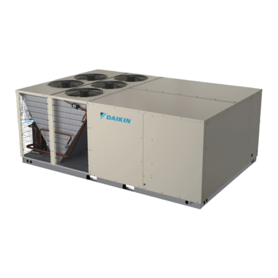
DSC Series
Packaged Heating and
Cooling Unit 15 to 25 Ton
NOTE:
25 ton model shown in picture.
20 ton model has 4 fans
15 ton model has 3 fans
RECOGNIZE THIS SYMBOL
AS A SAFETY PRECAUTION.
These installation instructions cover the outdoor installation
of single package heating and cooling units. See the
Specification Sheet applicable to your model for information
regarding accessories.
*NOTE: Please contact your distributor or our website
for the applicable Specification Sheet referred to in this
manual.
NOTE: This equipment is approved to use only with R-32
refrigerant.
NOTE: Specifications and performance data listed herein
are subject to change without notice.
NOTE: Never operate the unit without the recommended
filter or the outer panel installed.
Our continuing commitment to quality products may mean a change in specifications without notice.
© 2024
IOD-1068
05/2024
Only personnel that have been trained to install, adjust,
service, maintenance or repair (hereinafter, "service")
the equipment specified in this manual should service the
equipment.
This equipment is not intended for use by persons
(including children) with reduced physical, sensory or
mental capacities, or lack of experience and knowledge,
unless they have been given supervision or instruction
concerning use of the appliance by a person responsible
for their safety.
Children should be supervised to ensure that they do not
play with the equipment.
The manufacturer will not be responsible for any injury
or property damage arising from improper supervision,
service or service procedures. If you service this unit, you
assume responsibility for any injury or property damage
which may result. In addition, in jurisdictions that require
one or more licenses to service the equipment specified in
this manual, only licensed personnel should service the
equipment. Improper supervision, installation, adjustment,
servicing, maintenance or repair of the equipment specified
in this manual, or attempting to install, adjust, service
or repair the equipment specified in this manual without
proper supervision or training may result in product
damage, property damage, personal injury or death.
Do not bypass safety devices.
Safety Instructions .......................................................2
Replacement Parts ........................................................3
General Information .....................................................3
Unit Location ...................................................................5
Clearances ......................................................................7
Roof Curb Post-Installation Checks .........................7
Roof Top Duct Connections .........................................8
Rigging Details ...............................................................8
Electrical Wiring ..........................................................9
Circulating Air and Filters ........................................ 11
Condensate Drain Connection .................................. 11
Startup, Adjustments, and Checks ...........................12
Air Flow Adjustments .................................................14
Normal Sequence Of Operation - Cooling ..............15
Switch (CDTS) .............................................................16
19001 Kermier Rd. Waller, TX 77484
www.daikincomfort.com
INSTALLATION INSTRUCTIONS
WARNING
WARNING
TABLE OF CONTENTS
Advertisement
Table of Contents

Related Manuals for Daikin DSC Series


Summary of Contents for Daikin DSC Series
-
Page 1: Table Of Contents
INSTALLATION INSTRUCTIONS DSC Series WARNING Packaged Heating and Cooling Unit 15 to 25 Ton Only personnel that have been trained to install, adjust, service, maintenance or repair (hereinafter, “service”) the equipment specified in this manual should service the equipment. This equipment is not intended for use by persons... -
Page 2: Safety Instructions
Refrigeration Detection System (RDS) ....16 Maintenance ..............17 WARNING Appendix A Blower Performance Data ....22 Appendix B Electrical Data ........30 A tripped circuit breaker or blown fuse may indicate that an Appendix C Unit Dimensions ........45 electrical problem exists. Do not reset a circuit breaker or replace fuses without Appendix D Wiring Diagrams ........46 first performing thorough electrical troubleshooting and Start-up checklist ............57... -
Page 3: Replacement Parts
EQUIPMENT SUPPORT terminal cover or removing the electrical plug and servicing DAIKIN COMFORT TECHNOLOGIES the system. MANUFACTURING, L.P. 19001 KERMIER ROAD Proper sealed system evacuation is required during... - Page 4 Specification sheets calculated by an approved method or in accordance with can be found at www.daikincomfort.com for Daikin brand ASHRAE Guide or Manual J - Load Calculations published products. Within the website, please select the residential or by the Air Conditioning Contractors of America.
-
Page 5: Unit Location
or dispose of the packaging material according to Proper installation of the unit ensures trouble-free local codes. operation. Improper installation can result in problems ranging from noisy operation to property or equipment Pre-Installation Checks damages, dangerous conditions that could result in injury NOTE: Verify that voltage listed on serial plate or personal property damage. - Page 6 the roof must have sufficient structural strength to is located under the unit (under compressor). Also carry the weight of the unit(s) and snow or water remove the fork hole brackets as shown in the loads as required by local codes. Consult a structural following figure.
-
Page 7: Clearances
UNIT CLEARANCES WARNING Adequate clearance around the unit should be kept for safety, service, maintenance, and proper unit operation. A To prevent possible equipment damage, property damage, 75” clearance on the non-service side of the unit is required personal injury or death, the following bullet points must be observed when installing the unit. -
Page 8: Roof Top Duct Connections
ROOF TOP DUCT CONNECTIONS Refer to the Roof Curb Installation Instructions for proper curb installation. Curbing must be installed in compliance with the National Roofing Contractors Association Manual. Install duct connections on the roof curb before placing the Lower unit carefully onto roof mounting curb. While rigging unit on the rooftop. -
Page 9: Electrical Wiring
DSC Weights (lbs) DATA CAUTION Corner Weight - A To prevent damage to the wiring, protect wiring from sharp edges. Follow national electrical code and all local codes Corner Weight - B and ordinances. Do not route wires through removable Corner Weight - C access panels. - Page 10 CAUTION To prevent improper and dangerous operation due to FIELD CONNECTION FOR CONTROL WIRING AT wiring errors, label all wires prior to disconnection when TERMINAL BLOCK servicing controls. Verify proper operation after servicing. ROUTE FIELD CONTROL WIRING THROUGH GROMMET NOTE: A weather-tight disconnect switch, properly sized for the unit total load must be field or factory installed.
-
Page 11: Circulating Air And Filters
CIRCULATING AIR AND FILTERS Ductwork The supply duct from the unit through a wall may be installed without clearance. However, minimum unit clearances must be maintained (see “Clearances” section). The supply duct should be provided with an access panel large enough to inspect the air chamber downstream of the heat exchanger. -
Page 12: Startup, Adjustments, And Checks
Horizontal Drain Contractor Responsibility Drainage of condensate directly onto the roof may be The installing contractor must be certain that: acceptable; (refer to local code). It is recommended that • All supply and return air ductwork is in place, properly a small drip pad of either stone, mortar, wood or metal sealed, and corresponds with installation instructions. - Page 13 condition exists between phases. Calculate percent voltage unbalance as follows: Three Phase Models 2) MAXIMUM VOLTAGE DEVIATIONS 3) PERCENT VOLTAGE FROM AVERAGE VOLTAGE = 100 X UNBALANCE 1) AVERAGE VOLTAGE HOW TO USE THE FORMULA: EXAMPLE: With voltage of 220, 216, and 213 1) Average Voltage = 220+216+213=649 / 3 = 216 2) Maximum Voltage Deviations from Average Voltage = 220 - 216 = 4 3) Percent Voltage Unbalance = 100 x...
-
Page 14: Air Flow Adjustments
AIR FLOW ADJUSTMENTS NOTE: On units with DDC controls installed, air flow adjustments are made through settings in the DDC controller and speed tap adjustments are When the final adjustments are complete, the current draw not required. Refer to the DDC User Manual for of the motor should be checked and compared to the full details on making airflow adjustments. -
Page 15: Normal Sequence Of Operation - Cooling
Checking Superheat be made if suspecting a charge issue. EXAMPLE: b. If subcooling is low and superheat is high, add a. Suction Pressure = 143 PSI charge to raise subcooling then check superheat. b. Corresponding Temp. = 50°F c. If subcooling and superheat are high, adjust TXV c. -
Page 16: Compressor Discharge Temperature Switch (Cdts)
CDTS WARNING (ON CKT1) BURN HAZARD! DO NOT TOUCH! DISCHARGE LINE MAY BE HOT! 6. Check that each compressor is operating correctly. The scroll compressors in these units MUST operate in the proper rotation. To ensure the compressors are operating in the correct direction, check the compressor discharge line pressure or temperature after each compressor is started. - Page 17 RDS Operation During operation, the mitigation system is controlled by CAUTION a refrigerant sensor(s), which is secured to a designated location(s) for active monitoring. Throughout this period, the Sheet metal parts, screws, clips and similar items inherently HVAC operation stops, and the indoor blower fan remains have sharp edges, and it is necessary that the installer and service personnel exercise caution.
- Page 18 Step 3: Pull the part marked as ‘C’. This will allow the recovery of refrigerant). Cylinders shall be complete with sliding part to slide down by an inch. Once it slides down by pressure-relief valve and associated shut-off valves in good an inch, pull the strap and remove all filters one by one.
- Page 19 Clean Outside Coil The coil with the outside air flowing over it should be inspected annually and cleaned as frequently as necessary to keep the finned areas free of lint, hair and debris. NOTE: Clean the opposite direction of air flow. Maintenance of MicroChannel Heat Exchangers (MCHE) Frequent servicing is essential to maintaining the required...
- Page 20 Daikin recommends a quarterly cleaning of the coils, as the minimum. The cleaning frequency should be increased depending on the RDS - PCB level of dirt/dust accumulation and the environment (e.g.,...
- Page 21 RECOMMENDED ACTION FOR RDS PCB LED FLASHING CODES LED TROUBLESHOOT STATUS MODE DEFINITION LED FLASHING PATTERN RECOMMENDED ACTIONS NOTES Slow LED flashing pattern Normal Operation No faults to report. No actions needed. (2 seconds on and 2 seconds off) A technician will need to find where the refrigerant leak and In terms of the controls, no action is needed.
- Page 22 APPENDIX A BLOWER PERFORMANCE DATA DIRECT DRIVE - STANDARD DSC1803D Standard Static DSC2403D Standard Static Speed Static Airflow RPM 1 RPM 2 BHP 1 BHP 2 Speed Static Airflow RPM 1 RPM 2 BHP 1 BHP 2 3198 0.19 0.20 4426 0.29 0.30...
- Page 23 APPENDIX A BLOWER PERFORMANCE DATA DIRECT DRIVE - STANDARD DSC3003D Standard Static Speed Static Airflow RPM 1 RPM 2 BHP 1 BHP 2 5835 0.57 0.56 5496 0.63 0.62 5095 0.67 0.70 4723 0.72 0.75 4182 0.79 0.81 3784 0.83 0.84 7123 0.91...
- Page 24 APPENDIX A BLOWER PERFORMANCE DATA DIRECT DRIVE - HIGH STATIC DSC1803W High Static Speed Tap Static Airflow RPM 1 RPM 2 BHP 1 BHP 2 Speed Static Airflow RPM 1 RPM 2 BHP 1 BHP 2 6622 0.25 0.25 8163 1.33 1.23 6195...
- Page 25 APPENDIX A BLOWER PERFORMANCE DATA DIRECT DRIVE - HIGH STATIC DSC2403W High Static Speed Static Airflow RPM 1 RPM 2 BHP 1 BHP 2 Speed Static Airflow RPM 1 RPM 2 BHP 1 BHP 2 6412 0.71 0.69 9125 1.74 1.65 6081 0.77...
- Page 26 APPENDIX A BLOWER PERFORMANCE DATA DIRECT DRIVE - HIGH STATIC DSC3003W High Static Speed Static Airflow RPM 1 RPM 2 BHP 1 BHP 2 Speed Static Airflow RPM 1 RPM 2 BHP 1 BHP 2 7629 1.07 1.03 10268 2.58 2.41 7314 1.14...
- Page 27 APPENDIX A BLOWER PERFORMANCE DATA MODELS: DSC1803D, DSC1804D, DSC1807D STANDARD STATIC TO 3.5HP (0.2 ~1.2 ESP) RPM1 RPM2 DDC% BHP1 BHP2 RPM1 RPM2 DDC% BHP1 BHP2 RPM1 RPM2 DDC% BHP1 BHP2 3600 0.36 0.38 0.41 0.41 0.52 0.50 3900 0.36 0.37 0.43 0.43...
- Page 28 APPENDIX A BLOWER PERFORMANCE DATA MODELS: DSC2403D, DSC2404D, DSC2407D STANDARD STATIC TO 3.5HP (0.2 ~1.2 ESP) RPM1 RPM2 DDC% BHP1 BHP2 RPM1 RPM2 DDC% BHP1 BHP2 RPM1 RPM2 DDC% BHP1 BHP2 4800 0.42 1.18 0.53 1.07 0.66 1.05 5200 0.48 1.17 0.61 1.07...
- Page 29 APPENDIX A ECONOMIZER PRESSURE DROP Airflow Pressure Drop of Downflow Economizer for 15 to 25 Ton Rooftop Units (100% Return Air) SCFM 4500 5000 5500 6000 6500 7000 7500 8000 8500 9000 9500 10000 (In WG) 0.15 0.18 0.22 0.27 0.32 0.37 0.42...
- Page 30 APPENDIX B ELECTRICAL DATA Optional Power Powered Power Compressor Outdoor Fan Motor Indoor Fan Motor Optional Electric Heat Exhaust Power Supply Convenience Exhaust Model Electrical (Modulating) Outlet Number Rating Part Type DSC1803D 208/230/3/60 25.0 0.33 10.9 84.1/84.1 100/100 88.9/88.9 110/110 13.9 98.0/98.0 110/110...
- Page 31 APPENDIX B ELECTRICAL DATA Optional Power Powered Power Compressor Outdoor Fan Motor Indoor Fan Motor Optional Electric Heat Exhaust Power Supply Convenience Exhaust Model Electrical (Modulating) Outlet Number Rating Part Type DSC1804D 460/3/60 10.9 0.33 0.85 41.4 43.8 49.5 45.7 48.1 53.8 EH**-...
- Page 32 APPENDIX B ELECTRICAL DATA Optional Power Powered Power Compressor Outdoor Fan Motor Indoor Fan Motor Optional Electric Heat Exhaust Power Supply Convenience Exhaust Model Electrical (Modulating) Outlet Number Rating Part Type DSC1807D 575/3/60 78.0 0.33 0.67 31.0 33.0 39.3 34.5 36.5 42.8 EH**-...
- Page 33 APPENDIX B ELECTRICAL DATA Optional Power Powered Power Compressor Outdoor Fan Motor Indoor Fan Motor Optional Electric Heat Exhaust Power Supply Convenience Exhaust Model Electrical (Modulating) Outlet Number Rating Part Type DSC2403D 208/230/3/60 29.4 10.9 98.7/98.7 125/125 103/103 125/125 13.9 113/113 125/125 9.6/8.7...
- Page 34 APPENDIX B ELECTRICAL DATA Optional Power Powered Power Compressor Outdoor Fan Motor Indoor Fan Motor Optional Electric Heat Exhaust Power Supply Convenience Exhaust Model Electrical (Modulating) Outlet Number Rating Part Type DSC2403W 208/230/3/60 29.4 14.5 106/106 125/125 111/111 125/125 13.9 120/120 125/125 9.6/8.7...
- Page 35 APPENDIX B ELECTRICAL DATA Optional Power Powered Power Compressor Outdoor Fan Motor Indoor Fan Motor Optional Electric Heat Exhaust Power Supply Convenience Exhaust Model Electrical (Modulating) Outlet Number Rating Part Type DSC2404D 460/3/60 13.7 50.8 53.2 58.9 55.1 57.5 63.2 EH**- 28.8 34.6...
- Page 36 APPENDIX B ELECTRICAL DATA Optional Power Powered Power Compressor Outdoor Fan Motor Indoor Fan Motor Optional Electric Heat Exhaust Power Supply Convenience Exhaust Model Electrical (Modulating) Outlet Number Rating Part Type DSC2404W 460/3/60 13.7 10.6 57.6 60.0 65.7 61.9 64.3 70.0 EH**- 28.8...
- Page 37 APPENDIX B ELECTRICAL DATA Optional Power Powered Power Compressor Outdoor Fan Motor Indoor Fan Motor Optional Electric Heat Exhaust Power Supply Convenience Exhaust Model Electrical (Modulating) Outlet Number Rating Part Type DSC2407D 575/3/60 10.9 93.7 38.5 40.5 46.8 42.0 44.0 50.3 EH**- 28.8...
- Page 38 APPENDIX B ELECTRICAL DATA Optional Power Powered Power Compressor Outdoor Fan Motor Indoor Fan Motor Optional Electric Heat Exhaust Power Supply Convenience Exhaust Model Electrical (Modulating) Outlet Number Rating Part Type DSC2407W 575/3/60 10.9 93.7 42.9 44.9 51.2 46.4 48.4 54.7 EH**- 28.8...
- Page 39 APPENDIX B ELECTRICAL DATA Optional Power Powered Power Compressor Outdoor Fan Motor Indoor Fan Motor Optional Electric Heat Exhaust Power Supply Convenience Exhaust Model Electrical (Modulating) Outlet Number Rating Part Type DSC3003D 208/230/3/60 35.3 14.5 122/122 150/150 127/127 150/150 13.9 136/136 150/150 9.6/8.7...
- Page 40 APPENDIX B ELECTRICAL DATA Optional Power Powered Power Compressor Outdoor Fan Motor Indoor Fan Motor Optional Electric Heat Exhaust Power Supply Convenience Exhaust Model Electrical (Modulating) Outlet Number Rating Part Type DSC3003W 208/230/3/60 35.3 14.5 122/122 150/150 127/127 150/150 13.9 136/136 150/150 9.6/8.7...
- Page 41 APPENDIX B ELECTRICAL DATA Optional Power Powered Power Compressor Outdoor Fan Motor Indoor Fan Motor Optional Electric Heat Exhaust Power Supply Convenience Exhaust Model Electrical (Modulating) Outlet Number Rating Part Type DSC3004D 460/3/60 20.5 10.6 74.3 76.7 82.4 78.6 81.0 86.7 EH**- 28.8...
- Page 42 APPENDIX B ELECTRICAL DATA Optional Power Powered Power Compressor Outdoor Fan Motor Indoor Fan Motor Optional Electric Heat Exhaust Power Supply Convenience Exhaust Model Electrical (Modulating) Outlet Number Rating Part Type DSC3004W 460/3/60 20.5 10.6 74.3 76.7 82.4 78.6 81.0 86.7 EH**- 28.8...
- Page 43 APPENDIX B ELECTRICAL DATA Optional Power Powered Power Compressor Outdoor Fan Motor Indoor Fan Motor Optional Electric Heat Exhaust Power Supply Convenience Exhaust Model Electrical (Modulating) Outlet Number Rating Part Type DSC3007D 575/3/60 13.8 50.4 52.4 58.7 53.9 55.9 62.2 EH**- 28.8 27.7...
- Page 44 APPENDIX B ELECTRICAL DATA Optional Power Powered Power Compressor Outdoor Fan Motor Indoor Fan Motor Optional Electric Heat Exhaust Power Supply Convenience Exhaust Model Electrical (Modulating) Outlet Number Rating Part Type DSC3007W 575/3/60 13.8 50.4 52.4 58.7 53.9 55.9 62.2 EH**- 28.8 27.7...
- Page 45 APPENDIX C UNIT DIMENSIONS Model 15 Ton 133 - 7/8” 88 - 1/2” 51 - 11/16” 5 - 5/32” 20 Ton 133 - 7/8” 88 - 1/2” 5 - 5/32” 25 Ton NOTE: 15 ton models have 3 fans. 20 ton models have 4 fans 25 ton models have 5 fans 21"...
- Page 46 WIRING DIAGRAMS DSC180* Wiring is subject to change. Always refer to the wiring diagram on the unit for the most up-to-date wiring.
- Page 47 WIRING DIAGRAMS DSC180* Wiring is subject to change. Always refer to the wiring diagram on the unit for the most up-to-date wiring.
- Page 48 WIRING DIAGRAMS DSC240* Wiring is subject to change. Always refer to the wiring diagram on the unit for the most up-to-date wiring.
- Page 49 WIRING DIAGRAMS DSC240* Wiring is subject to change. Always refer to the wiring diagram on the unit for the most up-to-date wiring.
- Page 50 WIRING DIAGRAMS DSC300* Wiring is subject to change. Always refer to the wiring diagram on the unit for the most up-to-date wiring.
- Page 51 WIRING DIAGRAMS DSC300* Wiring is subject to change. Always refer to the wiring diagram on the unit for the most up-to-date wiring.
- Page 52 WIRING DIAGRAMS DSC 180-240 DDC Wiring is subject to change. Always refer to the wiring diagram on the unit for the most up-to-date wiring.
- Page 53 WIRING DIAGRAMS DSC 300 DDC Wiring is subject to change. Always refer to the wiring diagram on the unit for the most up-to-date wiring.
- Page 54 WIRING DIAGRAMS DSC 180 DDC Wiring is subject to change. Always refer to the wiring diagram on the unit for the most up-to-date wiring.
- Page 55 WIRING DIAGRAMS DSC 240 DDC Wiring is subject to change. Always refer to the wiring diagram on the unit for the most up-to-date wiring.
- Page 56 WIRING DIAGRAMS DSC 300 DDC Wiring is subject to change. Always refer to the wiring diagram on the unit for the most up-to-date wiring.
- Page 59 THIS PAGE IS LEFT INTENTIONALLY BLANK.
- Page 60 CUSTOMER FEEDBACK Daikin is very interested in all product comments. Please fill out the feedback form on the following link: https://daikincomfort.com/contact-us You can also scan the QR code on the right to be directed to the feedback page. PRODUCT REGISTRATION Thank you for your recent purchase.
Need help?
Do you have a question about the DSC Series and is the answer not in the manual?
Questions and answers