Daikin DCG Series Installation Instructions Manual
Light commercial packaged gas unit
Hide thumbs
Also See for DCG Series:
- Installation instructions manual (60 pages) ,
- Installation and maintenance manual (38 pages) ,
- Service instructions manual (135 pages)
Table of Contents
Advertisement
Quick Links
DCG
SERIES
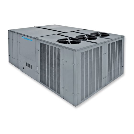
LIGHT COMMERCIAL PACKAGED GAS UNIT
15 to 25 T
oN
NOTE: 15 & 20 ton model shown in picture.
25 ton model has 2 fans.
ATTENTION INSTALLING PERSONNEL:
Prior to installation, thoroughly familiarize yourself with
this Installation Manual. Observe all safety warnings.
During installation or repair, caution is to be observed.
It is your responsibility to install the product safely and
to educate the customer on its safe use.
RECOGNIZE THIS SYMBOL
AS A SAFETY PRECAUTION.
These installation instructions cover the outdoor installation
of single package heating and cooling units. See the
Specification Sheet applicable to your model for information
regarding accessories.
*NOTE: Please contact your distributor or our website for
the applicable Specification Sheet referred to in this manual.
This Forced Air Central Unit Design Complies With
Requirements Embodied in the American National Standard
/ National Standard of Canada shown below.
ANSI Z21.47•CSA-2.3 C
IOD-1030A
03/2019
F
eNtrAl
urNACeS
Our continuing commitment to quality products may mean a change in specifications without notice.
©2018 - 2019
5151 San Felipe St., Suite 500, Houston, TX 77056
O
NLY PERSONNEL THAT HAVE BEEN TRAINED TO INSTALL
(
REPAIR
HEREINAFTER
SHOULD SERVICE THE EQUIPMENT
FOR ANY INJURY OR PROPERTY DAMAGE ARISING FROM IMPROPER SERVICE OR
SERVICE PROCEDURES
FOR ANY INJURY OR PROPERTY DAMAGE WHICH MAY RESULT
JURISDICTIONS THAT REQUIRE ONE OR MORE LICENSES TO SERVICE THE EQUIPMENT
SPECIFIED IN THIS MANUAL
. I
EQUIPMENT
MPROPER INSTALLATION
THE EQUIPMENT SPECIFIED IN THIS MANUAL
SERVICE OR REPAIR THE EQUIPMENT SPECIFIED IN THIS MANUAL WITHOUT PROPER
TRAINING MAY RESULT IN PRODUCT DAMAGE
INJURY OR DEATH
Replacement Parts .........................................................2
Safety Instructions .........................................................2
General Information .......................................................5
Unit Location ...................................................................5
Clearances ......................................................................8
Roof Curb Post-Installation Checks .............................8
Roof Top Duct Connections ..........................................8
Rigging Details ...............................................................8
Electrical Wiring .............................................................9
www.daikinac.com
INSTALLATION INSTRUCTIONS
, "
")
SERVICE
THE EQUIPMENT SPECIFIED IN THIS MANUAL
. T
HE MANUFACTURER WILL NOT BE RESPONSIBLE
. I
,
F YOU SERVICE THIS UNIT
YOU ASSUME RESPONSIBILITY
,
ONLY LICENSED PERSONNEL SHOULD SERVICE THE
,
ADJUSTMENT
,
OR ATTEMPTING TO INSTALL
,
PROPERTY DAMAGE
.
PROP 65 WARNING
FOR CALIFORNIA CONSUMERS
WARNING
Cancer and Reproductive Harm -
www.P65Warnings.ca.gov
Index
,
,
ADJUST
SERVICE OR
. I
,
N ADDITION
IN
,
SERVICING OR REPAIR OF
,
,
ADJUST
,
PERSONAL
0140M00517-A
Advertisement
Table of Contents

Related Manuals for Daikin DCG Series


Summary of Contents for Daikin DCG Series
-
Page 1: Table Of Contents
INSTALLATION INSTRUCTIONS SERIES LIGHT COMMERCIAL PACKAGED GAS UNIT 15 to 25 T NLY PERSONNEL THAT HAVE BEEN TRAINED TO INSTALL ADJUST SERVICE OR , “ ”) REPAIR HEREINAFTER SERVICE THE EQUIPMENT SPECIFIED IN THIS MANUAL SHOULD SERVICE THE EQUIPMENT HE MANUFACTURER WILL NOT BE RESPONSIBLE FOR ANY INJURY OR PROPERTY DAMAGE ARISING FROM IMPROPER SERVICE OR SERVICE PROCEDURES F YOU SERVICE THIS UNIT... -
Page 2: Replacement Parts
NSTALLATION AND SERVICE MUST BE PERFORMED BY A QUALIFIED telephone book or contact: INSTALLER SERVICE AGENCY OR THE GAS SUPPLIER EQUIPMENT SUPPORT DAIKIN NORTH AMERICA LLC WARNING 19001 KERMIER ROAD WALLER, TEXAS 77484 HOULD OVERHEATING OCCUR OR THE GAS SUPPLY FAIL TO SHUT OFF... - Page 3 WARNING O NOT CONNECT TO OR USE ANY DEVICE THAT IS NOT DESIGN CERTIFIED BY THE MANUFACTURER FOR USE WITH THIS UNIT ERIOUS PROPERTY DAMAGE PERSONAL INJURY REDUCED UNIT PERFORMANCE OR HAZARDOUS CONDITIONS MAY RESULT FROM THE USE OF SUCH NON APPROVED DEVICES WARNING “...
- Page 4 WARNING AVERTISSEMENT CARBON MONOXIDE POISONING HAZARD RISQUE D’INTOXICATION AU MONOXYDE DE CARBONE Failure to follow the steps outlined below for each appliance connected to the venting system being placed into operation could result in carbon monoxide poisoning or death. Si les étapes décrites ci-dessous ne sont pas suivies pour chacun des appareils raccordés au système de ventilation au The following steps shall be followed with each appliance moment de sa mise en marche, cela peut entraîner une intoxica-...
-
Page 5: General Information
Specification sheets can be found at www.daikinac.com for the cabinetry. Any bolts or screws which may have loosened Daikin brand products. Within the website, please select the in transit must be re-tightened. In the event of damage, the residential or commercial products menu and then select the... - Page 6 • When the unit is heating, the temperature of the return NStAllAtIONS air entering the unit must be between 50° F and 100° F. : Unit should be energized 24 hours pri- mPOrtANt rOuND evel NStAllAtIONS or to compressor start up to ensure crankcase heater •...
- Page 7 3. Lift unit per the “Rigging Details” section of this manual, NStAllAtIONS observing all warnings and cautions. When unit is Before installing this unit... lifted, boards and shipping brace will drop if screws have been removed. To avoid injury, STAND CLEAR. IMPORTANT NOTE: This unit has been equipped with a 4.
-
Page 8: Clearances
CLEARANCES ROOF CURB POST-INSTALLATION CHECKS After installation, check the top of the curb, duct connection frame and duct flanges to make sure gasket has been applied properly. Gasket should be firmly applied to the top of the curb perimeter, duct flanges and any exposed duct connec- tion frame. -
Page 9: Electrical Wiring
Important: If using bottom discharge with roof curb, ductwork should be attached to the curb prior to installing the unit. DCG Weights Ductwork dimensions are shown in Roof Curb Installation (lbs) Instructions. DATA 15 Tons 20 Tons 25 Tons Refer to the Roof Curb Installation Instructions for proper curb installation. - Page 10 (ANSI-NFPA 70). A ground lug is provided for this CAUTION purpose. Size grounding conductor in accordance with Table 250-95 of the National Electrical Code. O PREVENT DAMAGE TO THE WIRING PROTECT WIRING FROM SHARP Do not use the ground lug for connecting a neutral EDGES OLLOW NATIONAL ELECTRICAL CODE AND ALL LOCAL CODES conductor.
-
Page 11: Gas Supply Piping
3. Use #18 AWG wire for 24V control wiring runs not WARNING exceeding 75 feet. Use #16 AWG wire for 24V control wiring runs not exceeding 125 feet. Use #14 AWG wire AILURE OF UNIT DUE TO OPERATION ON IMPROPER LINE VOLTAGE for 24V control wiring runs not exceeding 200 feet. - Page 12 4. Install a drip leg to trap dirt and moisture before it can INLET GAS PRESSURE enter the gas valve. The drip leg must be a minimum of three inches long. NATURAL Min. 5.0" W.C., Max. 10.0" W.C. 5. Use two pipe wrenches when making connection to PROPANE Min.
-
Page 13: Propane Gas Installations
NOTE: The unit gas supply entrance is factory sealed with must be within 9.7 - 10.3 inches w.c. for high fire and within plugs. Keep plugs in place until gas supply is ready to be 6.7 - 7.3 inches w.c. low fire at the manifold with all gas installed. -
Page 14: Circulating Air And Filters
CIRCULATING AIR AND FILTERS Z223.1). NOTE: The gas connection size at the unit does NOT uCtwOrk establish the size of the supply line. The supply duct should be provided with an access panel 3. These units are designed for either natural or large enough to inspect the air chamber downstream of the propane (LP) gas and are specifically constructed at heat exchanger. -
Page 15: Startup, Adjustments, And Checks
leANING emPOrAry eAtING OOlING Due to the fact that drain pans in any air conditioning unit If the unit is to be used for temporary heating or cooling, a will have some moisture in them, algae and fungus will “Startup, Adjustments, and Checks” must first be performed in grow due to airborne bacteria and spores. -
Page 16: Air Flow Adjustments
System Voltage - That nominal voltage value assigned to vAPOrAtOr OtAtION heCk a circuit or system for the purpose of designating its voltage Check that fan rotates clockwise when viewed from the drive class. side of unit and in accordance with rotation arrow shown on blower housing. -
Page 17: Motor Sheave Adjustments
NOTE: Future adjustments should be made by loosening the belt tension and increasing or decreasing the pitch diameter of the sheave by half or full turns as required. Readjust belt tension before starting drive. *Apply force to the center of the span. t = Span length, inches C = Center distance, inches VL &... - Page 18 NOTE: Except during brief periods when gas pressures are MAXIMUM NUMBER GAS ORIFICES MAXIMUM being measured by qualified service personnel, the furnace INPUT BTUH/BURNER NATURAL PROPANE (LP) access panel must always be secured in place when the (BTUH) BURNERS furnace is in operation. An inspection port in the access panel 350,000 50,000 is provided to monitor the flame.
- Page 19 the pressure regulator adjustment. In no case should the final Pressure Regulator Outlet Pressure manifold pressure vary more than plus or minus 0.3 inches Adjustment water column from the specified nominal pressure. Any major (Under Cap Screw) changes in flow should be made by changing the size of the burner orifices.
-
Page 20: Normal Sequence Of Operation - Heating
PS located in the burner compartment. the control then CAUTION initiates a 15-second pre-purge time delay. During this period, the vent motor will clear the combustion chamber of any residual gas. O PREVENT UNRELIABLE OPERATION OR EQUIPMENT DAMAGE GAS MANIFOLD PRESSURE MUST BE AS SPECIFIED ON THE UNIT 5. -
Page 21: Normal Sequence Of Operation - Cooling
(AlS) 5. Turn the fan switch to “Auto” position. The blower uxIlIAry eSet ImIt ONtrOl should stop after a 65 second delay. Located in the blower compartment on the blower housing, it 6. Slowly lower the cooling temperature until first stage senses air temperature within the blower compartment and COOL (LOW COOL) starts. -
Page 22: Maintenance
2. To simulate a mechanical call for cooling from the wall will cycle off and IIC (pin 12) will initiate its time delay thermostat, place a jumper across terminals R and Y1 cycle. The compressor and the supply fan will cycle of terminal block TB1. - Page 23 Flame Sensor (Qualified Servicer Only) 3. Lubricate motor bearings. A drop in the flame current can be caused by a nearly invisi- 4. Align or replace belts as needed. ble coating on the flame sensor. This coating, created by the 5.
-
Page 24: Troubleshooting
ignition attempts (five attempts total) before locking out. The WARNING diagnostic fault code is 1 flash for a lockout due to failed ignition attempts or flame dropouts. The integrated control O AVOID PERSONAL INJURY OR DEATH DUE TO ELECTRIC SHOCK will automatically reset after one hour, or it can be reset by NOT REMOVE ANY INTERNAL COMPARTMENT COVERS OR ATTEMPT ANY removing the thermostat signal or disconnecting the electrical... - Page 25 Open Thermal Protection Device (4 FLASH CODE) If the primary limit switch opens, the gas valve is immediately deenergized, the induced draft and air circulating blowers are energized. The induced draft and air circulator blowers re- main energized until the limit switch recloses. The diagnostic fault code for an open limit is four (4) flashes.
-
Page 26: Appendix A Blower Performance Data
APPENDIX A BLOWER PERFORMANCE DATA BELT DRIVE - STANDARD DCG180 STANDARD TWO-SPEED BELT DRIVE TURNS OPEN ESP, In H 0.00 6827 2.67 6394 2.28 5982 1.94 7079 3.20 6623 2.76 6161 2.34 5706 1.98 5271 1.66 6903 3.32 6405 2.83 5923 2.41 5434... - Page 27 APPENDIX A BLOWER PERFORMANCE DATA — — BELT DRIVE - HIGH STATIC DCG180 HIGH STATIC DOWNSHOT TWO SPEED MODELS TURNS OPEN (In. W.C.) 6678 4.61 6266 4.10 6600 4.90 6126 4.32 5626 3.79 6840 5.80 6540 5.25 6078 4.58 5634 4.03 5115 3.51 6739...
- Page 28 APPENDIX A ECONOMIZER PRESSURE DROP Airflow Pressure Drop of Downflow Economizer for 15 to 25 Ton Rooftop Units (100% Return Air) SCFM 4500 5000 5500 6000 6500 7000 7500 8000 8500 9000 9500 10000 (In WG) 0.15 0.18 0.22 0.27 0.32 0.37 0.42...
-
Page 29: Appendix B Electrical Data
APPENDIX B ELECTRICAL DATA Compressor Compressor Optional Powered Outdoor Fan Motor Indoor Fan Motor Power Supply Electrical Circuit 1 Circuit 2 Convienience Outlet Model Number Rating Type 82.6 / 82.6 100 / 100 2-Speed High DCG180XXX3W 208/230-3-60 25.0 164.0 25.0 164.0 0.33 7.50... -
Page 30: Appendix C Unit Dimensions
APPENDIX C UNIT DIMENSIONS Model 15 Ton 88-7/32" 50-9/32" 5-5/32" 133-1/2" 20 Ton 25 Ton 133-1/2" 88-7/32" 53-9/32" 5-5/32" NOTE: 15 & 20 ton models have 3 fans. 25 ton models have 2 fans. 21” 60” 7” 48” 22” VERTICAL DISCHARGE (TOP VIEW) -
Page 31: Appendix D Wiring Diagrams
APPENDIX D WIRING DIAGRAMS... - Page 32 WIRING DIAGRAMS DCG180*/ DCG240* 208-230/ 3 / 60 2 SPEED CCH1 CCHR1 COMP CCH2 CCHR2 POWER SUPPLY SEE NOTE 4 208V / 240V - 3 ph - 60Hz COMP GRND GRND HIGH SPEED HIGH SPEED CCR1 CCR2 UNUSED UNUSED HEAT HEAT COOL COOL...
- Page 33 WIRING DIAGRAMS DCG180*/ DCG240* 208-230/ 3 / 60 2 SPEED SUPPLY VOLTAGE 208-240/3/60 5. FOR TWO STAGE OPERATION REMOVE W1 TO W2 WIRE JUMPER. HPS2 LPS2 ECON STATUS LIGHT EQUIPMENT STATUS CHECK ------ NORMAL OPERATION CHECK INPUT POWER NO POWER OR CHECK FUSE ON CONTROL INTERNAL CONTROL REPLACE CONTROL...
- Page 34 WIRING DIAGRAMS DCG180*/ DCG240* 460, 575/ 3 / 60 2 SPEED CCH1 CCHR1 COMP CCH2 CCHR2 POWER SUPPLY SEE NOTE 4 460V / 575V - 3 ph - 60Hz COMP GRND GRND HIGH SPEED HIGH SPEED OR APPROPRIATE INPUT VOLTAGE CCR1 CCR2 UNUSED...
- Page 35 DCG180* / DCG240* 460, 575/ 3 / 60 2 SPEED WIRING DIAGRAMS Wiring is subject to change. Always refer to the wiring diagram on the unit for the most up-to-date wiring.
- Page 36 WIRING DIAGRAMS DCG300* 208-230/ 3 / 60 2 SPEED POWER DIAGRAM IIC DIAGNOSTIC BLINK CODES DCG300***3 STAT US LIGHT EQUIPMENT STATUS CHECK NORMAL OPERATION ------- CHECK INPUT POWER NO POWER OR CHECK FUSE ON CONTROL INTERNAL CONTROL LINE VOLTAGE REPLACE CONTROL GAS FLOW GAS PRESSURE IGNITION FAILURE...
- Page 37 WIRING DIAGRAMS DCG300* 460, 575/ 3 / 60 2 SPEED POWER DIAGRAM IIC DIAGNOSTIC BLINK CODES DCG300***(4,7) STATUS LIGHT EQUIPMENT STATUS CHECK NORMAL OPERATION ------- CHECK INPUT POWER NO POWER OR CHECK FUSE ON CONTROL INTERNAL CONTROL LINE VOLTAGE REPLACE CONTROL GAS FLOW GAS PRESSURE IGNITION FAILURE...
- Page 38 DCG300* 208-230, 460, 575/ 3 / 60 2 SPEED WIRING DIAGRAMS FIELD THERMOSTAT WIRING SMOKE DETECTOR CONTROL 2 STAGE COOLING WIRING CLASS 2 SEN1 SENSOR 1 AUX A SUPPLY (LINE) VOLTAGE SENSOR 2 SEN2 AUX B 24 VAC SMK DET STAT OPTION HPS1...
- Page 39 wIrING DIAGrAmS FOr mODelS wIth DDC CONtrOlS For complete information and installation instructions for models with DDC controls, see manual DK-DDC-TGD-XXX...
- Page 40 WIRING DIAGRAMS DCG0180*/ DCG240* 208-230 / 3 / 60 2 SPeeD IIC DIAGNOSTIC BLINK CODES POWER WIRING DIAGRAM LINE VOLTAGE STATUS LIGHT EQUIPMENT STATUS CHECK DCG(180-240) ****3 NORMAL OPERATION ------- CHECK INPUT POWER NO POWER OR CHECK FUSE ON CONTROL INTERNAL CONTROL REPLACE CONTROL GAS FLOW...
- Page 41 DCG0180*/ DCG240* 460, 575 / 3 / 60 2 SPeeD WIRING DIAGRAMS IIC DIAGNOSTIC BLINK CODES POWER WIRING DIAGRAM LINE VOLTAGE STATUS LIGHT EQUIPMENT STATUS CHECK DCG(180-240) ****4,7 ------- NORMAL OPERATION CHECK INPUT POWER NO POWER OR CHECK FUSE ON CONTROL INTERNAL CONTROL REPLACE CONTROL GAS FLOW...
- Page 42 WIRING DIAGRAMS DCG0180*/ DCG240* 208-230, 460, 575 / 3 / 60 2 SPeeD Wiring is subject to change. Always refer to the wiring diagram on the unit for the most up-to-date wiring.
- Page 43 WIRING DIAGRAMS DCG300* 208 / 230 / 3 / 60 2 SPeeD Wiring is subject to change. Always refer to the wiring diagram on the unit for the most up-to-date wiring.
- Page 44 WIRING DIAGRAMS DCG300* 460 / 575 / 3 / 60 2 SPeeD Wiring is subject to change. Always refer to the wiring diagram on the unit for the most up-to-date wiring.
- Page 45 THIS PAGE INTENTIONALLY LEFT BLANK...
-
Page 46: Start-Up Checklist
Start-up Checklist *Store in job file Date: ________________________________ Location: _______________________________________ Model Number: ________________________________ _______________________________________ Serial Number: ________________________________ _______________________________________ Technician: ________________________________ Unit #: _______________________________________ Pre Start-Up (Check each item as completed) Verify all packaging material has been removed. Remove all shipping brackets per installation instructions. Verify the job site voltage agrees with the unit serial plate. - Page 47 Start-up Checklist Start-Up (Insert the values as each item is completed.) ELECTRICAL Supply Voltage L1 - L2 L2 - L3 L3 - L1 Circuit 1 Compressor Amps Circuit 2 Compressor Amps Blower Amps Condenser Fan Amps Fan 1 Fan 2 Fan 3 BLOWER EXTERNAL STATIC PRESSURE Return Air Static Pressure...
- Page 48 CUSTOMER FEEDBACK Daikin is very interested in all product comments. Please fill out the feedback form on the following link: https://daikincomfort.com/contact-us You can also scan the QR code on the right to be directed to the feedback page. Our continuing commitment to quality products may mean a change in specifications without notice.
Need help?
Do you have a question about the DCG Series and is the answer not in the manual?
Questions and answers