Daikin DSG Series Installation Instructions Manual
Packaged gas/electric unit 15 to 25 ton
Hide thumbs
Also See for DSG Series:
- Installation instructions manual (136 pages) ,
- Wiring diagram (20 pages) ,
- Installation instructions manual (60 pages)
Table of Contents
Advertisement
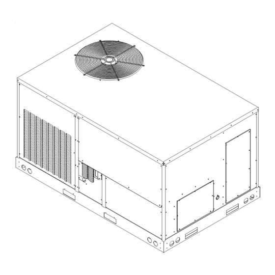
DSG Series
PACKAGED GAS/ELECTRIC
UNIT 15 to 25 Ton
NOTE: 25 ton model shown in picture.
20 ton model has 4 fans
15 ton model has 3 fans
RECOGNIZE THIS SYMBOL
AS A SAFETY PRECAUTION.
These installation instructions cover the outdoor installation
of single package heating and cooling units. See the
Specification Sheet applicable to your model for information
regarding accessories.
*NOTE: Please contact your distributor or our website
for the applicable Specification Sheet referred to in this
manual.
This Forced Air Central Unit Design Complies With
Requirements Embodied in the American National
Standard / National Standard of Canada shown below.
ANSI Z21.47•CSA-2.3 Central Furnaces.
NOTE: This equipment is approved to use only with R-32
refrigerant.
NOTE: Specifications and performance data listed herein
are subject to change without notice.
NOTE: Never operate the unit without the recommended
filter or the outer panel installed.
Our continuing commitment to quality products may mean a change in specifications without notice.
© 2024
IOD-1069
05/2024
Only personnel that have been trained to install, adjust,
service, maintenance or repair (hereinafter, "service")
the equipment specified in this manual should service the
equipment.
This equipment is not intended for use by persons
(including children) with reduced physical, sensory or
mental capacities, or lack of experience and knowledge,
unless they have been given supervision or instruction
concerning use of the appliance by a person responsible
for their safety.
Children should be supervised to ensure that they do not
play with the equipment.
The manufacturer will not be responsible for any injury
or property damage arising from improper supervision,
service or service procedures. If you service this unit, you
assume responsibility for any injury or property damage
which may result. In addition, in jurisdictions that require
one or more licenses to service the equipment specified in
this manual, only licensed personnel should service the
equipment. Improper supervision, installation, adjustment,
servicing, maintenance or repair of the equipment specified
in this manual, or attempting to install, adjust, service
or repair the equipment specified in this manual without
proper supervision or training may result in product
damage, property damage, personal injury or death.
Do not bypass safety devices.
Safety Instructions .......................................................2
Replacement Parts ........................................................4
General Information .....................................................4
Unit Location ...................................................................5
Clearances ......................................................................8
Roof Curb Post-Installation Checks .........................8
Roof Top Duct Connections .........................................8
Rigging Details ...............................................................9
Electrical Wiring ........................................................10
Gas Supply Piping .........................................................12
Propane Gas Installations .........................................13
Circulating Air and Filters ........................................15
Venting ...........................................................................15
Condensate Drain Connection ..................................15
Startup, Adjustments, and Checks ...........................15
Air Flow Adjustments .................................................16
19001 Kermier Rd. Waller, TX 77484
www.daikincomfort.com
INSTALLATION INSTRUCTIONS
WARNING
WARNING
Table of Contents
Advertisement
Table of Contents

Related Manuals for Daikin DSG Series


Summary of Contents for Daikin DSG Series
-
Page 1: Table Of Contents
INSTALLATION INSTRUCTIONS DSG Series WARNING PACKAGED GAS/ELECTRIC UNIT 15 to 25 Ton Only personnel that have been trained to install, adjust, service, maintenance or repair (hereinafter, “service”) the equipment specified in this manual should service the equipment. This equipment is not intended for use by persons... -
Page 2: Safety Instructions
Gas System Check ............18 Normal Sequence of Operation - Heating ....21 WARNING Superheat and Subcooling .........22 Start-up Procedure and Checklist ......23 Do not use means to accelerate the defrosting process Normal Sequence Of Operation - Cooling ....23 or to clean, other than those recommended by the manufacturer. - Page 3 RISQUE D'EMPOISONNEMENT AU MONOXYDE DE CARBONE Advertencia especial para la instalación de calentadores ó manejadoras de aire en áreas cerradas como estacionamientos ó cuartos de servicio. Cette ventilation est nécessaire pour éviter le danger d'intoxication Las emisiones de monóxido de carbono pueden circular a través au CO pouvant survenir si un appareil produisant du monoxyde del aparato cuando se opera en cualquier modo.
-
Page 4: Replacement Parts
Specification percentage of gas (25% maximum) is confirmed. sheets can be found at www.daikincomfort.com for Daikin brand products. Within the website, please select the Leak detection fluids are also suitable for use with... -
Page 5: Unit Location
National Codes d. Copy of the inspection report issued by the carrier This product is designed and manufactured to permit representative at the time damage is reported to installation in accordance with National Codes. It is the the carrier. The carrier is responsible for making installer’s responsibility to install the product in accordance prompt inspection of damage and for a thorough with National Codes and/or prevailing local codes and... - Page 6 some climates or locations, it may be necessary to WARNING elevate the unit to avoid these problems. • When the unit is heating, the temperature of the return air entering the unit must be between 50°F and 100°F. The appliance shall be installed, operated and stored in a room with a floor area not less than the minimum room area indicated.
- Page 7 Roof Curb Installations Only: 3. Lift unit per the “Rigging Details” section of this Before installing this unit... manual, observing all warnings and cautions. When IMPORTANT NOTE: This unit has been equipped with a unit is lifted, boards and shipping brace will drop if shipping brace under the compressor section that MUST screws have been removed.
-
Page 8: Clearances
See the manual shipped with the roof curb for assembly and installation instructions. CLEARANCES Unit Clearances Adequate clearance around the unit should be kept for safety, service, maintenance, and proper unit operation. A 75” clearance on the non-service side of the unit is required to facilitate possible blower assembly and coil Roof Curb Installation removal. -
Page 9: Rigging Details
RIGGING DETAILS 60” or more WARNING To prevent property damage, the unit should remain in an upright position during all rigging and moving operations. To facilitate lifting and moving when a crane is used, place the unit in an adequate cable sling. CAUTION Do not lift units two at a time. -
Page 10: Electrical Wiring
to the maximum overcurrent protection device. DO NOT CAUTION EXCEED THE MAXIMUM OVERCURRENT DEVICE SIZE SHOWN ON UNIT DATA PLATE. To prevent severe damage to the bottom of the unit, do not All line voltage connections must be made through fork lift unit after wood struts have been removed. - Page 11 • Some disconnect switches are not fused. Protect the power leads at the point of distribution in accordance WARNING with the unit data plate. • The unit must be electrically grounded in accordance Failure of unit due to operation on improper line voltage or with local codes or, in the absence of local codes, with excessive phase unbalance constitutes product abuse and is not covered by the warranty.
-
Page 12: Gas Supply Piping
2. Locate thermostat or remote sensor in the conditioned INLET GAS PRESSURE space where it will sense average temperature. Do NATURAL Min. 5.0" W.C., Max. 10.0" W.C. not locate the device where it may be directly exposed to supply air, sunlight or other sources of heat. Follow PROPANE Min. -
Page 13: Propane Gas Installations
4. Install a drip leg to trap dirt and moisture before it can NOTE: The unit gas supply entrance is factory sealed with enter the gas valve. The drip leg must be a minimum plugs. Keep plugs in place until gas supply is ready to be of three inches long. - Page 14 For satisfactory operation, propane gas manifold pressure pressure. All piping must be done in accordance with must be within 9.7 - 10.3 inches w.c. for high fire and within local codes or, in the absence of local codes, with the 6.7 - 7.3 inches w.c.
-
Page 15: Circulating Air And Filters
required and must never be used. The power ventor Install condensate drain trap as shown. Use 1” drain line will supply an adequate amount of combustion air and fittings or larger. Do not operate without trap. as long as the air passageways are kept free of any obstructions and the recommended external unit NOTE: All threaded connection should be seal clearances are maintained. -
Page 16: Air Flow Adjustments
The Startup, Adjustments, and Checks procedure provides identification plate and is within the utilization voltage range a step-by-step sequence which, if followed, will assure the as indicated in Appendix C Electrical Data. proper startup of the equipment in the minimum amount of time. - Page 17 • Taps T1 and T2 are for low cool operation (cooling stage 1) and Taps T3 to T5 are for high cool operation (cooling stage 2). • Taps T6 and T7 are for low heat operation (heating stage 1) and taps T8 to T10 are for high heat operation (heating stage 2).
-
Page 18: Gas System Check
Low Cool Y1, Yellow (YL) is movable and set to TB1-T1. 9. Open the manual gas valve external to the unit. Low Heat W1, White (WH) is movable and set to TB1-T6. 10. Turn on the electrical power supply to the unit. High Cool Y2, Purple (PU) is movable and set to TB1-T3. - Page 19 full fire. A supply pressure tap is provided on the upstream Gas Inlet Pressure Check side of the gas valve. A manifold pressure tap is provided Gas inlet pressure must be checked and adjusted in on the manifold. The normal manifold pressure for full input accordance to the type of fuel being consumed.
- Page 20 To measure the gas input use a gas meter and proceed as follows: 1. Turn off gas supply to all other appliances except the unit. High Fire Regulator Adjust 2. With the unit operating, time the smallest dial on the Regulator Vent meter for one complete revolution.
-
Page 21: Normal Sequence Of Operation - Heating
1. All registers must be open; all duct dampers must be 8. If the control is unable to ignite the burners after its in their final (fully or partially open) position and the initial attempt, it will initiate another purge and spark unit operated for 15 minutes on HIGH FIRE before sequence. -
Page 22: Superheat And Subcooling
The reason for elevated temperatures at the control should Checking Superheat be determined and repaired prior to resetting this manual EXAMPLE: reset control. a. Suction Pressure = 143 PSI b. Corresponding Temp. = 50°F c. Thermometer on Suction Line = 59°F WARNING To obtain the degrees temperature of superheat, subtract To avoid property damage, personal injury or death due to... -
Page 23: Start-Up Procedure And Checklist
d. If subcooling is high and superheat is low, adjust does not occur and the compressor is producing an TXV valve superheat and remove charge to lower exceptional amount of noise, this indicates that there the subcooling. is a phasing issue. Perform the following to correct: NOTE: Do NOT adjust the charge based 7.1 Turn power to the unit OFF. -
Page 24: Compressor Discharge Temperature Switch (Cdts)
COMPRESSOR DISCHARGE G, and across R and Y on TB1 terminal block. Close the disconnect switch. The following operational sequence TEMPERATURE SWITCH (CDTS) should be observed. 1. Current through primary winding of transformer Compressor Discharge Temperature Switch (CDTS) is a TRANS1 energizes the 24-volt control circuit. -
Page 25: Refrigeration Detection System Rds
MAINTENANCE YL/PK LPS1 YL/PK WARNING ELECTRIC SHOCK, FIRE OR EXPLOSION HAZARD Failure to follow safety warnings exactly could result in dangerous operation, serious injury, death or property CDTS1 damage. Improper servicing could result in dangerous operation, serious injury, death or property damage. BL/PK HPS1 BL/PK... - Page 26 10. Check operation of all safety controls. 11. Examine gas furnaces (see below and the User’s Information Manual). 12. Check condenser fans and tighten set screws. Filters CAUTION To prevent property damage due to fire and loss of equip- ment efficiency or equipment damage due to dust and lint build up on internal parts, never operate unit without an air filter installed in the return air system.
- Page 27 Clean Indoor Coil (Qualified Servicer Only) • Ensure that contamination of different refrigerants Before cleaning the indoor coil, A2L sensor must be does not occur when using charging equipment. removed from the unit to avoid damage and contamination. • Hoses or lines shall be as short as possible to Air filters should also be removed before performing minimize the amount of refrigerant contained in them.
- Page 28 Daikin recommends a quarterly cleaning of the coils, as the minimum. The cleaning frequency should be increased depending on the level of dirt/dust accumulation and the environment (e.g.,...
-
Page 29: Troubleshooting
NOTE: Use all screws that were removed; they are Remove the control box access panel and note the number necessary for safe and proper operation of the of diagnostic LED flashes. Refer to Diagnostic Indicator unit. Chart for an interpretation of the signal and to this section for an explanation. - Page 30 blower, or insufficient combustion air. The rollout protection Flame Detected with Gas Valve Closed device is a manual reset limit located on the burner (5 FLASH CODE) bracket. The cause of the flame rollout must be determined If flame is detected with the gas valve deenergized, the and corrected before resetting the limit.
- Page 31 LED STATUS MODE LED FLASHING PATTERN SLOW LED FLASHING PATTERN NORMAL OPERATION (2 SECONDS ON 2 SECONDS OFF) FAST LED FLASHING PATTERN R-32 LEAK ALARM DELAY MODE LED WILL BE ON CONTINUOUSLY SYSTEM FAST LED FLASHING PATTERN VERIFICATION MODE CONTROL BOARD INTERNAL LED WILL FLASH 2 TIMES AND THEN FAULT BE OFF FOR 5 SECONDS...
- Page 32 RECOMMENDED ACTION FOR RDS PCB LED FLASHING CODES LED TROUBLESHOOT STATUS MODE DEFINITION LED FLASHING PATTERN RECOMMENDED ACTIONS NOTES Slow LED flashing pattern Normal Operation No faults to report. No actions needed. (2 seconds on and 2 seconds off) A technician will need to find where the refrigerant leak and In terms of the controls, no action is needed.
-
Page 33: Appendix A Blower Performance Data
APPENDIX A BLOWER PERFORMANCE DATA DIRECT DRIVE - STANDARD DSG1803DL Standard Static DSG1803DM Standard Static SPEED Static AIR FLOW RPM 1 RPM 2 BHP 1 BHP 2 RPM 1 RPM2 BHP1 BHP2 3395 0.19 0.18 3187 0.19 0.16 2923 0.22 0.21 2666 0.20... - Page 34 APPENDIX A BLOWER PERFORMANCE DATA DIRECT DRIVE - STANDARD DSG1803DH Standard Static DSG2403DL Standard Static RPM 1 RPM2 BHP1 BHP2 Speed Static Airflow RPM 1 RPM 2 BHP 1 BHP 2 4070 0.33 0.30 3187 0.19 0.16 3699 0.36 0.33 2666 0.20 0.20...
- Page 35 APPENDIX A BLOWER PERFORMANCE DATA DIRECT DRIVE - STANDARD DSG2403DM Standard Static DSG2403DH Standard Static RPM 1 RPM2 BHP1 BHP2 Speed Static Airflow RPM 1 RPM 2 BHP 1 BHP 2 4070 0.33 0.30 4070 0.33 0.30 3699 0.36 0.33 3699 0.36 0.33...
- Page 36 APPENDIX A BLOWER PERFORMANCE DATA DIRECT DRIVE - STANDARD DSG3003DL Standard Static DSG3003DM Standard Static Speed Static Airflow RPM 1 RPM 2 BHP 1 BHP 2 Speed Static Airflow RPM 1 RPM 2 BHP 1 BHP 2 5761 0.67 0.60 5761 0.67 0.60...
- Page 37 APPENDIX A BLOWER PERFORMANCE DATA DIRECT DRIVE - STANDARD DSG3003DH Standard Static Speed Static Airflow RPM 1 RPM 2 BHP 1 BHP 2 5761 0.67 0.60 5491 0.71 0.65 5161 0.74 0.70 4806 0.78 0.75 4447 0.82 0.79 4092 0.86 0.83 6955 1.08...
- Page 38 APPENDIX A BLOWER PERFORMANCE DATA DIRECT DRIVE - HIGH STATIC DSG1803WL High Static Speed Static Airflow RPM 1 RPM 2 BHP 1 BHP 2 Speed Static Airflow RPM 1 RPM 2 BHP 1 BHP 2 6185 0.28 0.26 8228 1.37 1.27 5843 0.29...
- Page 39 APPENDIX A BLOWER PERFORMANCE DATA DIRECT DRIVE - HIGH STATIC DSG1803WM High Static Speed Static Airflow RPM 1 RPM 2 BHP 1 BHP 2 Speed Static Airflow RPM 1 RPM 2 BHP 1 BHP 2 6185 0.28 0.26 8958 1.47 1.36 5843 0.29...
- Page 40 APPENDIX A BLOWER PERFORMANCE DATA DIRECT DRIVE - HIGH STATIC DSG1803DWH High Static Speed Static Airflow RPM 1 RPM 2 BHP 1 BHP 2 Speed Static Airflow RPM 1 RPM 2 BHP 1 BHP 2 6185 0.28 0.26 9745 1063 2.28 2.11 5843...
- Page 41 APPENDIX A BLOWER PERFORMANCE DATA DIRECT DRIVE - HIGH STATIC DSG2403WL High Static Speed Static Airflow RPM 1 RPM 2 BHP 1 BHP 2 Speed Static Airflow RPM 1 RPM 2 BHP 1 BHP 2 6244 0.82 0.74 6475 0.90 0.81 5984 0.86...
- Page 42 APPENDIX A BLOWER PERFORMANCE DATA DIRECT DRIVE - HIGH STATIC DSG2403WM High Static Speed Static Airflow RPM 1 RPM 2 BHP 1 BHP 2 Speed Static Airflow RPM 1 RPM 2 BHP 1 BHP 2 6244 0.82 0.74 9426 1038 2.33 2.09 5984...
- Page 43 APPENDIX A BLOWER PERFORMANCE DATA DIRECT DRIVE - HIGH STATIC DSG2403WH High Static Speed Static Airflow RPM 1 RPM 2 BHP 1 BHP 2 Speed Static Airflow RPM 1 RPM 2 BHP 1 BHP 2 6244 0.82 0.74 9880 1078 2.64 2.37 5984...
- Page 44 APPENDIX A BLOWER PERFORMANCE DATA DIRECT DRIVE - HIGH STATIC DSG3003WL High Static Speed Static Airflow RPM 1 RPM 2 BHP 1 BHP 2 Speed Static Airflow RPM 1 RPM 2 BHP 1 BHP 2 7461 1.28 1.15 7565 1.33 1.19 7225 1.33...
- Page 45 APPENDIX A BLOWER PERFORMANCE DATA DIRECT DRIVE - HIGH STATIC DSG3003WM High Static Speed Static Airflow RPM 1 RPM 2 BHP 1 BHP 2 Speed Static Airflow RPM 1 RPM 2 BHP 1 BHP 2 7461 1.28 1.15 9308 1027 2.25 2.02 7225...
- Page 46 APPENDIX A BLOWER PERFORMANCE DATA DIRECT DRIVE - HIGH STATIC DSG3003WH High Static Speed Static Airflow RPM 1 RPM 2 BHP 1 BHP 2 Speed Static Airflow RPM 1 RPM 2 BHP 1 BHP 2 7461 1.28 1.15 9880 1078 2.64 2.37 7225...
- Page 47 APPENDIX A BLOWER PERFORMANCE DATA MODELS: DSG1803WL, DSG1804WL, DSG1807WL STANDARD STATIC TO 3.5HP (0.2 ~1.2 ESP) RPM1 RPM2 DDC% BHP1 BHP2 RPM1 RPM2 DDC% BHP1 BHP2 RPM1 RPM2 DDC% BHP1 BHP2 3600 0.52 0.44 0.52 0.49 0.56 0.53 3900 0.50 0.42 0.52 0.48...
- Page 48 APPENDIX A BLOWER PERFORMANCE DATA MODELS: DFG1803DM, DFG1803DH, DFG1804DM, DFG1804DH, DFG1807DM, DFG1807DH STANDARD STATIC TO 3.5HP (0.2 ~1.2 ESP) RPM1 RPM2 DDC% BHP1 BHP2 RPM1 RPM2 DDC% BHP1 BHP2 RPM1 RPM2 DDC% BHP1 BHP2 3600 0.52 0.44 0.52 0.49 0.56 0.53 3900 0.50...
- Page 49 APPENDIX A BLOWER PERFORMANCE DATA MODELS: DFG2403WL, DFG2404WL, DFG2407WL STANDARD STATIC TO 3.5HP (0.2 ~1.2 ESP) RPM1 RPM2 DDC% BHP1 BHP2 RPM1 RPM2 DDC% BHP1 BHP2 RPM1 RPM2 DDC% BHP1 BHP2 4800 0.47 0.42 0.59 0.53 0.70 0.65 5200 0.58 0.52 0.71 0.64...
- Page 50 APPENDIX A BLOWER PERFORMANCE DATA MODELS: DFG2403DM, DFG2403DH, DFG2404DM, DFG2404DH, DFG2407DM, DFG2407DH STANDARD STATIC TO 3.5HP (0.2 ~1.2 ESP) RPM1 RPM2 DDC% BHP1 BHP2 RPM1 RPM2 DDC% BHP1 BHP2 RPM1 RPM2 DDC% BHP1 BHP2 4800 0.47 0.42 0.59 0.53 0.70 0.65 5200 0.58...
- Page 51 APPENDIX A ECONOMIZER PRESSURE DROP Airflow Pressure Drop of Downflow Economizer for 15 to 25 Ton Rooftop Units (100% Return Air) SCFM 4500 5000 5500 6000 6500 7000 7500 8000 8500 9000 9500 10000 (In WG) 0.15 0.18 0.22 0.27 0.32 0.37 0.42...
-
Page 52: Appendix B Electrical Data
APPENDIX B ELECTRICAL DATA Optional Power Optional Electric Powered Power Model Electrical Compressor Outdoor Fan Motor Indoor Fan Motor Exhaust Power Supply Heat Convenience Exhaust Number Rating (Modulating) Outlet Type HP FLA Part # KW* FLA DSG1803D 208/230/3/60 84.1/84.1 100/100 88.9/88.9 110/110 98.0/98.0... - Page 53 APPENDIX B ELECTRICAL DATA Optional Power Optional Electric Powered Power Model Electrical Compressor Outdoor Fan Motor Indoor Fan Motor Exhaust Power Supply Heat Convenience Exhaust Number Rating (Modulating) Outlet Type HP FLA Part # KW* FLA DSG2403W 208/230/3/60 106/106 125/125 111/111 125/125 120/120...
- Page 54 APPENDIX B ELECTRICAL DATA Optional Power Optional Electric Powered Power Model Electrical Compressor Outdoor Fan Motor Indoor Fan Motor Exhaust Power Supply Heat Convenience Exhaust Number Rating (Modulating) Outlet Type HP FLA Part # KW* FLA DSG3004D 460/3/60 74.3 76.7 82.4 78.6 81.0...
-
Page 55: Appendix C Unit Dimensions
APPENDIX C UNIT DIMENSIONS Model 15 Ton 133 - 7/8” 88 - 1/2” 51 - 11/16” 5 - 5/32” 20 Ton 133 - 7/8” 88 - 1/2” 5 - 5/32” 25 Ton NOTE: 15 ton models have 3 fans. 20 ton models have 4 fans 25 ton models have 5 fans 21"... -
Page 56: Appendix D Wiring Diagrams
WIRING DIAGRAMS DSG180* Wiring is subject to change. Always refer to the wiring diagram on the unit for the most up-to-date wiring. - Page 57 WIRING DIAGRAMS DSG180* Wiring is subject to change. Always refer to the wiring diagram on the unit for the most up-to-date wiring.
- Page 58 WIRING DIAGRAMS DSG240* Wiring is subject to change. Always refer to the wiring diagram on the unit for the most up-to-date wiring.
- Page 59 WIRING DIAGRAMS DSG240* Wiring is subject to change. Always refer to the wiring diagram on the unit for the most up-to-date wiring.
- Page 60 WIRING DIAGRAMS DSG300* Wiring is subject to change. Always refer to the wiring diagram on the unit for the most up-to-date wiring.
- Page 61 WIRING DIAGRAMS DSG300* Wiring is subject to change. Always refer to the wiring diagram on the unit for the most up-to-date wiring.
- Page 62 WIRING DIAGRAMS DSG180 - 240 DDC Wiring is subject to change. Always refer to the wiring diagram on the unit for the most up-to-date wiring.
- Page 63 WIRING DIAGRAMS DSG300 DDC Wiring is subject to change. Always refer to the wiring diagram on the unit for the most up-to-date wiring.
- Page 64 WIRING DIAGRAMS DSG180 DDC Wiring is subject to change. Always refer to the wiring diagram on the unit for the most up-to-date wiring.
- Page 65 WIRING DIAGRAMS DSG240 DDC Wiring is subject to change. Always refer to the wiring diagram on the unit for the most up-to-date wiring.
- Page 66 WIRING DIAGRAMS DSG300 DDC Wiring is subject to change. Always refer to the wiring diagram on the unit for the most up-to-date wiring.
- Page 69 THIS PAGE INTENTIONALLY LEFT BLANK...
- Page 70 THIS PAGE INTENTIONALLY LEFT BLANK...
- Page 71 THIS PAGE INTENTIONALLY LEFT BLANK...
- Page 72 CUSTOMER FEEDBACK Daikin is very interested in all product comments. Please fill out the feedback form on the following link: https://daikincomfort.com/contact-us You can also scan the QR code on the right to be directed to the feedback page. PRODUCT REGISTRATION Thank you for your recent purchase.
Need help?
Do you have a question about the DSG Series and is the answer not in the manual?
Questions and answers