
Related Manuals for Thermo Scientific 61-12N-64P


Summary of Contents for Thermo Scientific 61-12N-64P
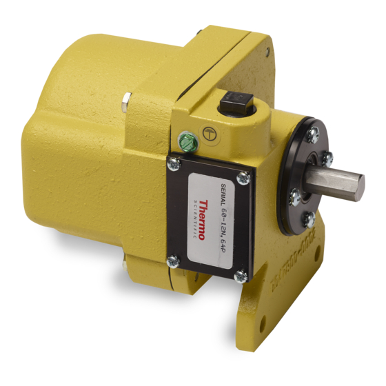
- Page 1 Thermo Fisher Scientific™ Speed Sensor Model 61-12N-64P Operating and Service Manual REC 4374 Rev C Part Number 136294—English...
- Page 2 REC 4374 Rev C Part Number 136294—English This document is confidential and is the property of Thermo Fisher Scientific. It may not be copied or reproduced in any way without the express written consent of Thermo Fisher Scientific. This document also is an unpublished work of Thermo Fisher Scientific.
- Page 3 Revision Number Date Revised ECO Number Revision Specifics Revision A January 2014 3391 New Release Revision B September 22, 2016 4227 Update to Hazardous Revision C September 20,2019 5053 Added metric coupling NO CHANGES TO THIS DOCUMENT WITHOUT AGENCY APPROVAL Ramsey Model 61-12N Speed Sensor REC 4374B Page 3...
-
Page 4: Table Of Contents
Table of Contents Table of Contents ....................4 Introduction ....................... 5 Overview......................5 Application ..................... 5 Unpacking and Inspection ................6 Storage ......................6 Specifications ....................6 Installation ......................6 Overview......................6 Coupling Installation ..................7 Restraint Arm Installation ................8 Alternate Sensor Location ................ -
Page 5: Introduction
Overview The Thermo Scientific Model 61-12N-64P Speed Sensor is designed and constructed for direct connection to a conveyor tail pulley, snugging roll, or large diameter return roller. The speed sensor employs an optical pulse generator producing a stream of pulses, each pulse representing a unit of belt travel. -
Page 6: Unpacking And Inspection
Storage The Model 61-12N-64P Speed Sensor can be safely stored indoors, between -50 and +85 degrees C (-58 to +185 degrees F). The unit must be protected against moisture. Specifications... -
Page 7: Coupling Installation
Thread in supplied stub shaft coupling (part #037711) so that coupling collar bottoms out against tail pulley or snubbing shaft. See Figure 2. Insert 61-12N-64P speed sensor into coupling. Be sure to align shaft flat spots with set screws on coupling. Tighten all set screws securely. -
Page 8: Restraint Arm Installation
It would be advisable to provide two flat surfaces, 90º apart, on the stub shaft for a good set screw holding power. Note: If possible, weld coupling to tail pulley shaft. Do not weld to any part of 61-12N-64P speed sensor. Align shaft flat spots with set screws on coupling. See Figure 3. Tighten all set screws securely. -
Page 9: Alternate Sensor Location
Note: The pu pose of this ou ti g a a ge e t is to allo the speed se so to float a d a o odate any slight misalignment of the coupling. Therefore, no resultant bearing stress is applied due to misalignment, ill a slight o le of the de i e esult i ele t i al e o s. - Page 10 Speed Sensor must not be mounted rigid. Use restraint arm and retaining spring. Mechanical stop and spring mount are by others. Atta h sp i g i lo atio su h as to gi e / sp i g st et h. All wiring by others in accordance with system field wiring diagram and applicable codes.
- Page 11 Install 1/2 inch flexible conduit to the speed sensor housing. For 61-12N-64P use Belden 8772 or equivalent, 3 conductor, 20 AWG, shielded. Maximum distance is 500 feet (150 meters). For distances of 500 to 3000 feet (150-915 meters), use Belden #1036A or equivalent, 3 conductor, 18 AWG shielded.
-
Page 12: Operations
Figure 7. 61-12N-64P Output Voltage Waveform Model 61-12N-64P The 61-12N-64P has a 64 pulse per revolution optical encoder and can be used for speeds from 0 to 350 RPM. The output of the 61-12N- P is a ope -d ai t pe, hi h e ui es a e te al pull-up resistance. - Page 13 Troubleshooting Place a DC voltmeter across field terminals 17 (+) and 16 (-) of 61-12N-64P speed sensor. Reading should be equal to the source voltage from the integrator. If no voltage present, check at integrator terminals (see scale integrator manual).
-
Page 14: Service, Repair & Replacement Parts
Parts Lists The list below provides part numbers and descriptions of the replaceable parts for the 61-12N-64P Speed Sensor. ITEM DESCRIPTION PART NO. 61-12N-64P (64 pulse, 24 VDC) 133748 Clamp Bar (Restraint Arm) 002920 Coupling, Stub Shaft, Speed Sensor 037711 (IMPERIAL) / 131185 (METRIC) Coupling Shaft, .625 Bore... -
Page 15: Centering Template For Speed Sensor
Centering Template for Speed Sensor Ramsey Model 61-12N Speed Sensor REC 4374B Page 16... -
Page 16: Appendix A - Drawings
Appendix A – Drawings List of drawings Drawing 07392BE041 Drawing 07392BE042 Drawing 07392BE043...
Need help?
Do you have a question about the 61-12N-64P and is the answer not in the manual?
Questions and answers