
Related Manuals for Thermo Scientific 61-12C


Summary of Contents for Thermo Scientific 61-12C
- Page 1 Model 61-12C (FM) or 61-12 C/CSA Speed Sensor Operating and Service Manual REC 3449 Rev M P/N 013984...
- Page 3 Revision History Revision Number Date ECO Number Release Specifics March 1995 December 1995 January 1990 March 1991 September 1991 February 1993 May 1999 February 2001 April 2001 July 2006 December 2007 November 2008...
- Page 4 ©2007 Thermo Fisher Scientific. All rights reserved. This document is confidential and is the property of Thermo Fisher Scientific (Thermo Scientific). It may not be copied or reproduced in any way without the express written consent of Thermo Fisher Scientific. This doc- ument also is an unpublished work of Thermo Fisher Scientific.
- Page 5 "EXCEPT FOR THOSE WARRANTIES SPECIFICALLY CONTAINED HEREIN, SELLER DISCLAIMS ANY AND ALL WARRANTIES WITH RESPECT TO THE EQUIPMENT DELIVERED HEREUNDER, INCLUDING THE IMPLIED WARRANTIES OF MERCHANTABILITY AND FITNESS FOR USE. THE SOLE LIABILITY OF SELLER ARISING OUT OF THE WARRANTY CONTAINED HEREIN SHALL BE EXCLUSIVELY LIMITED TO BREACH OF THOSE WARRANTIES.
-
Page 7: Table Of Contents
Coupling Installation ............. 2-1 Restraint Arm Installation ..........2-3 Electrical wiring ............2-7 Chapter 3 Operation ..............3-1 Overview ..............3-1 Model 61-12C............... 3-1 Chapter 4 Maintenance..............4-1 Overview ..............4-1 Calibration ..............4-1 Chapter 5 Service, Repair, and Replacement Parts....5-1 Parts Ordering Information ........... - Page 8 Contents Thermo Fisher Scientific...
- Page 9 List of Figures Figure 1-1. Model 61-12C Speed Sensor..........1 - 1 Figure 2-1. Method A Installation ............2 - 2 Figure 2-2. Method B Installation ............2 - 2 Figure 2-3. Mounting Illustration .............2 - 4 Figure 2-4. Field Wiring Model 61-12 C Speed Sensor ......2 - 7 Figure 3-1.
- Page 10 REC 3349 Rev M Thermo Fisher Scientific...
- Page 11 This Guide is organized into five chapters and two appendices. this Guide – gives you Chapter 1: Introduction to the Model 61-12C (FM) Speed Sensor an overview of the device’s capabilities, describes its functions, and lists it technical specifications. – provides Chapter 2: Installing the Model 61-12 C (FM) Speed Sensor information about the installation of the speed sensor.
- Page 12 About this Manual Documentation The following conventions are used in this manual to help easily identify Conventions certain types of information. Bold is used the first time a new term is introduced. Italic is used to for emphasis and terms that have already been introduced.
- Page 13 About this Manual Safety Messages Instructions in this manual may require special precautions to ensure the safety of the personnel performing the operations. There are two levels of safety messages: warnings and cautions. The distinction between the two is as follows: CAUTION.
- Page 14 About this Manual CAUTION. High voltage that may be present on leads could cause electrical shock. • The main isolator switch must be OFF when checking input AC electrical connections, removing or inserting any electrical item, or attaching voltmeters to the system. •...
- Page 15 About this Manual Thermo Fisher Scientific REC 3449 Rev M...
- Page 16 About this Manual REC 3449 Rev M Thermo Fisher Scientific...
-
Page 17: Chapter 1 Introduction
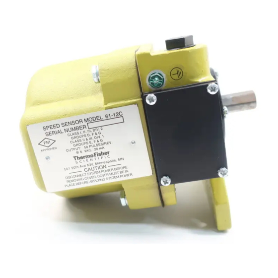
The Model 61-12 C (FM) is Factory Mutual (FM) approved for Class I, Division II, Groups D and Class II, Divisions I and II, Groups E, F, G. Figure 1-1. Model 61-12C Speed Sensor Thermo Fisher Scientific REC 3449 Rev M... -
Page 18: Application
Introduction Unpacking and Inspection Application The speed sensor is coupled to a rotating shaft which drives a generator inside the housing. The Model 61-12 C Speed Sensor has a usable range between 20 and 200 RPM. The frequency of the speed sensor output signal is exactly proportional to shaft speed and provides the required speed input to a Integrator/Totalizer. -
Page 19: Chapter 2 Installation
Chapter 2 Installation Overview The Model 61-12 C Speed Sensor must be attached to a pulley shaft which turns at true conveyor belt speed. Normally, the tail pulley shaft or a snubbing roll shaft satisfies this requirement. In installations where the tail pulley or snubbing roll shaft is not accessible, an additional pulley must be installed specifically for the speed sensor. -
Page 20: Figure 2-1. Method A Installation
Installation Overview Figure 2-1. Method A Installation Method “B” If customer's tail pulley shaft has a 5/8" diameter stub shaft extending from it and is concentric with the centerline of the driving shaft, use part #002931 to couple 61-12 speed sensor to tail pulley shaft. (Refer to Figure 2-2.) This coupling is not supplied with the speed sensor but may be purchased separately from Thermo Fisher Scientific. -
Page 21: Restraint Arm Installation
Installation Restraint Arm Installation Restraint Arm 1. Attach restraint arm to speed sensor with two (supplied) 5/16" x Installation 1-1/4" bolts. See Figure 2-3. The restraint arm should be mounted in a direction that will allow the sensor restraint arm to twist against the mechanical stop and in the direction of belt travel. - Page 22 Installation Alternate Sensor Location CAUTION. Unless the installation is consistent with the illustrations shown in Figures 2-1, 2-2, and 2-3, and as described above, the warranty on the device is void. REC 3449 Rev M Thermo Fisher Scientific...
-
Page 23: Figure 2-3. Mounting Illustration
Installation Alternate Sensor Location Figure 2-3. Mounting Illustration 1. Speed Sensor must not be mounted rigid. Use restraint arm and retaining spring. Mechanical stop and spring mount are by others. 2. Attach spring in location such as to give 1/2” spring stretch. 3. - Page 24 Installation Alternate Sensor Location Speed Minimum “A” Maximum “A” 100 FPM 2” 14” 200 FPM 4” 36” 300 FPM 6” 48” 400 FPM 8” 60” 500 FPM 10” 60” 600 FPM 12” 60” 700 FPM 14” 60” 800 FPM 16” 60”...
- Page 25 Installation Alternate Sensor Location 5/8-11 A0041d A0041a A0041c A0041b 1. Speed Sensor to be driven by conveyor tail pulley shaft or by special return roll. 2. Unit must be directly coupled to driving shaft. Do not drive with chains, belts, gears, etc. 3.
-
Page 26: Electrical Wiring
Installation Electrical Wiring Electrical Wiring WARNING. This device is rated for use in areas described as: Class I, Division 2, Group D, and Class II, Divisions 1 and 2, Groups E, F, and G as defined by the National Electrical Code (NEC). - Page 27 Installation Electrical Wiring CAUTION. The speed sensor must be connected to a solid earth ground. A ground terminal screw (green) is connected to the housing by Thermo Fisher Scientific. Earth ground wire to be provided by others. See Figure 2-4. Notes: 1.
- Page 28 Installation Electrical Wiring 2-10 REC 3449 Rev M Thermo Fisher Scientific...
-
Page 29: Chapter 3 Operation
Chapter 3 Operation Overview The speed sensor element employs a brushless, pulse generator which produces a stream of pulses, each pulse representing a unit of belt travel. The frequency of the pulse stream is proportional to true belt speed. The pulse output signal is fed to the Integrator/ Totalizer. -
Page 30: Figure 3-2. 61-12C Output Voltage Waveform
Operation Motor MFG Color Superior SS25 White Black Oriental White Black C8115-925 Source Eng. 57TYG002 Blue White Figure 3-2. 61-12C Output Voltage Waveform REC 3449 Rev M Thermo Fisher Scientific... -
Page 31: Chapter 4 Maintenance
Chapter 4 Maintenance Overview When performing scale calibration, it is a good practice to inspect the shaft cou- pling for tightness. Also verify that the restraint arm is free to move. If arm has worn a slot in the restraint stop and the restraint bar cannot float back and forth as well as against the spring, corrections should be made. - Page 32 Maintenance Calibration REC 3449 Rev M Thermo Fisher Scientific...
-
Page 33: Chapter 5 Service, Repair, And Replacement Parts
Service, Repair, and Replacement Parts This chapter provides information about service, repair, and replacement parts for your Thermo Scientific product. It includes the telephone numbers for various departments at Thermo Fisher Scientific, the procedure for ordering replacement parts, a Return Material Authorization (RMA) Form, and the appropriate parts lists. -
Page 34: Parts Ordering Information
Service, Repair, and Replacement Parts Parts Ordering Information Parts Ordering For the fastest service when ordering parts, telephone or FAX the Thermo Information Fisher Scientific Parts Department at the numbers given below. Your regional field service representative can also assist you with parts orders. The recommended procedure for ordering parts is: 1. -
Page 35: Contact Information
Service, Repair, and Replacement Parts Parts Ordering Information 501 90 Avenue N.W. 1-800-445-3503 Minneapol is, MN 554 33 Fax: 76 3.783.2525 501 90 Avenue N.W. 1-800-445-3503 11/27/2008 www.t hermo.com Minneapol is, MN 554 33 Fax: 76 3.783.2525 11/27/2008 www.t hermo.com Dear Customer, Thank you for using our i n-house repair servi ce. - Page 36 Service, Repair, and Replacement Parts Parts Ordering Information 501 90 Avenue N.W. 1-800-445-3503 Minneapol is, MN 554 33 Fax: 76 3.783.2525 11/27/2008 www.t hermo.com PRODUCT INFORMATION: Part number: ______________________________ Part Description: ____________________________ Problem description: _____________________________________________________________________ ______________________________________________________________________ ______________________________________________________________________ ______________________________________________________________________ Part number: ______________________________ Part Description: ____________________________ Problem description: _____________________________________________________________________...
- Page 37 Service, Repair, and Replacement Parts Parts Ordering Information 501 90 Avenue N.W. 1-800-445-3503 Minneapol is, MN 554 33 Fax: 76 3.783.2525 11/27/2008 www.t hermo.com DECONTAMINATION FORM Please complete all areas of the Decontamination Declaration below. • Orders without a Decontamination Declaration will not be processed and the instrument will be returned to the sender via collect freight.
- Page 38 Service, Repair, and Replacement Parts Thermo Fisher Scientific Offices Thermo Fisher Here is a list of Thermo Fisher Scientific offices worldwide. Scientific Offices Australia +61 (0) 8 8208 8200 +61 (0) 8 8234 3772 (fax) Canada +1 (905) 888-8808 +1 (905) 888-8828 (fax) Chile +56 (0) 2 378 8050 +56 (0) 2 370 1082 (fax)
- Page 39 Service, Repair, and Replacement Parts Thermo Fisher Scientific Offices United Kingdom +44 (0) 1788-820300 +44 (0) 1788-820301 (fax) United States +1 (800) 445-3503 +1 (763) 783-2525 (fax) +1 (763) 783-2500 (direct) Thermo Fisher Scientific REC 3449 Rev M...
-
Page 40: Parts List
Return Material Authorization Number, before shipping any product for disposal. Parts List This list provides part numbers and descriptions of the replaceable parts for the Model 61-12C Speed Sensor. ITEM DESCRIPTION PART NO. Speed Sensor, Model 61-12C/FM 005995 Speed Sensor Accessories: Diode, Zener IN4734A, 5.6-V... -
Page 41: Figure 5-1. Centering Template For Speed Sensor
Service, Repair, and Replacement Parts Parts List Figure 5-1. Centering Template for Speed Sensor Thermo Fisher Scientific REC 3449 Rev M... - Page 42 Service, Repair, and Replacement Parts Parts List 5-10 REC 3449 Rev M Thermo Fisher Scientific...
-
Page 43: Appendix A Engineering Drawings
Appendix A Engineering Drawings This appendix contains engineering drawings for your Model 61-12 C Speed Sensor. The following drawing is included. • Outline and Installation Diagram, Speed Sensor Model 61-12 C (FM Approved) - C07046A-B019 Thermo Fisher Scientific REC 3449 Rev M... - Page 44 Engineering Drawings REC 3449 Rev M Thermo Fisher Scientific...
-
Page 45: Appendix B Factory Mutual Report
Appendix B Factory Mutual Report Overview This appendix contains Factory Mutual Report 3007635 on the 61-12C Speed Sensor. Thermo Fisher Scientific REC 3449 Rev M... - Page 46 Factory Mutual Report Overview REC 3449 Rev M Thermo Fisher Scientific...
- Page 47 Factory Mutual Report Overview Thermo Fisher Scientific REC 3449 Rev M...
- Page 48 Factory Mutual Report Overview REC 3449 Rev M Thermo Fisher Scientific...
- Page 49 Factory Mutual Report Overview Thermo Fisher Scientific REC 3449 Rev M...
- Page 50 Factory Mutual Report Overview REC 3449 Rev M Thermo Fisher Scientific...
Need help?
Do you have a question about the 61-12C and is the answer not in the manual?
Questions and answers